Hybrid based Self-Test Solution for Embedded System
on Chip
Sherif I. Morsy
Egyptian Armed Forces Cairo, Egypt
Mohamed H. El-Mahlawy
Egyptian Armed Forces Cairo, Egypt
Gouda I. Mohamed
Egyptian Armed Forces Cairo, Egypt
ABSTRACT
Microcontrollers have become a widely accepted architecture for highly complex embedded systems on a single chip (SoC). It consists of deeply embedded heterogeneous components with poor accessibility makes their testing process a difficult task using hardware based self-test (HBST). Software-based self-test (SBST) is considered to be a promising testing technology for these systems. Almost every SoC contains at least one embedded processor, SBST utilize this processor for test pattern generation (TPG) and test response compaction (TRC) based on its instruction set, then test response will be unloaded and evaluated using external automatic test equipment (ATE). In this paper, SBST strategy disadvantages in microcontroller testing will be identified. Then, a new testing approach that combines both the HBST and the SBST, called hybrid-based self-test (HYBST) will be introduced. Based on a divide-and-conquer approach, HYBST identify microcontroller's components and their corresponding component operations. Feasibility and effectiveness of HYBST and SBST methodologies will be assessed by applying them to a Microchip® PIC16F877A and PIC18F452 in terms of memory usage, time consumption and number of tested modules found in microcontrollers.
General Terms
Embedded systems, Digital circuits testing
Keywords
Software-based self-test, Hybrid-based self-test, Microcontroller testing, Divide and conquer.
1.
INTRODUCTION
Almost every complex System-on-Chip (SoC) consists of at least one embedded processor core. Such processor are surrounded by a number of heterogeneous components with poor accessibility makes their testing process a difficult task. Built-in self-test (BIST) mechanism provides significant advantages in SoC testing. The use of self-test methodologies for processor testing reduces yield loss and drives down the overall test cost of the SoC [1]. In addition, the use of self-test reduces the design cycle and thus improves time-to-market. When a self-test methodology is based on hardware mechanisms, special parts must be added to the system design for test pattern generation and output data evaluation. Recent applications of hardware-based commercial logic BIST techniques in large industrial designs and microprocessors [2-4], revealed that extensive design changes have to be performed (most of them manually).
These changes have a negative impact on the circuit area, performance and power consumption, which can be considered of limited practical value. An alternative to HBST techniques is SBST techniques, which have the advantage that they utilize the processor functionality and instruction set for creating both TPG and TRC routines and thus do not add hardware or performance overheads in the optimized design.
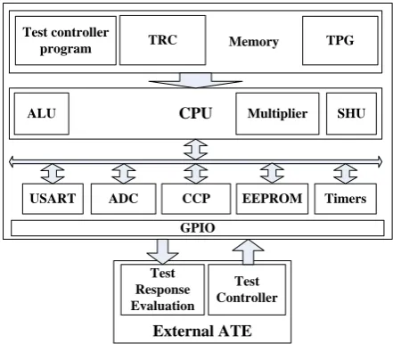
Figure 1 illustrates the embedded software-based self-testing concept, where test program is resided in microcontroller’s flash memory. During the application of the tests, the on-chip test generation program emulates a test pattern generator to generate required test patterns. The test patterns are applied to each of the microcontroller by the on-chip test application program. The test application program also collects the test responses and saves them to the memory after being compressed into response signatures using the test response compaction program. Test responses can later be unloaded and analyzed by an external ATE. At the final stage, the external ATE will give a decision about the microcontroller under test either to go or no go.
Microcontroller Memory
CPU
TPG
USART Test controller
program
ADC CCP EEPROM Timers
GPIO
External ATE
Test Response Evaluation
Test Controller
ALU Multiplier SHU
TRC
Fig 1: System environment of SBST for microcontrollers
Considerable work had been done in the field of microprocessor testing using either functional or structural SBST that will be discussed in the following literature.
1.1
Functional software-based self-testing
techniques
According to [5], there are various functional SBST approaches, which can be classified into the following two categories:
1. Tests based upon prior functional fault models.
2. Tests based on the checking of experiment principle, without assuming any prior fault model.
1.1.1
Functional tests based on prior fault models
During the late 70‘s and early 80‘s, a microprocessor functional model and test algorithm based on the functional fault modeling was presented by Abraham, Thatte and Brahme [6, 7].
[image:1.595.317.538.327.520.2]Van de Goor et al. [10]. However, most of these methods were not automated, and there was no reported fault coverage at the structural level for complex processors. The aim of test generation that is common feature in these approaches is to minimize the instruction sequence and to detect all functional faults. However, such a test suppresses certain instruction sequences, and it does not necessarily result in the highest structure-level fault coverage.
1.1.2
Functional tests derived without prior fault
models
J. Shen, J. A. Abraham [5] and Bellon et al. [12] proposed a testing strategy that does not depend on a prior functional model. These methodologies conclude functional testing of embedded microprocessors achieves low fault coverage because it does not consider the RTL structure and it is not based on the fault models. Therefore, functional test could not provide an alternative to structure-level test and manufacturers still had to resort to gate level test generation. Limitations of the functional SBST arises the need of the structural SBST.
1.2
Structural software-based self-testing
techniques
In 2001, Li Chen Presented structural SBST methodology [4] that targets specific components and fine tuning the test development to gate-level details of the PARWAN® processor core. This approach does not consider the regular structure of critical processor components and, hence, leads to large self-test code, large memory requirements, and excessive self-test application time, even when applied to a small processor model.
Kranitis et al. [13] presented promising techniques in 2003 for efficient testing of a Plasma/MIPS processor deeply embedded in an embedded system. Based on a divide-and-conquer test strategy, processor components and their corresponding component operations are firstly identified. Then, for every CUT within the processor and for every operation of the CUT, test patterns are generated targeting structural faults. After that, the test patterns are transformed to self-test routines (consisting of processor instruction sequences) which are used to apply test patterns to the inputs of the CUT and collect test responses from the outputs of the CUT. This approach also uses regular deterministic TPG.
Kranitis et al. [14] presented a structural SBST methodology in 2005, that define a processor‘s component based test strategy with different test priorities. They presented a SBST methodology that can be applied when just an RT-level description and the instruction set architecture of the processor are available. The key characteristics of this SBST methodology for complex embedded processors are the following:
A divide-and-conquer test strategy is applied using component-based test development.
Test development is based only on the ISA of the processor and its RTL description, which is, in almost all cases, available without the need of low gate-level fine tuning.
Kranitis et al. [15] introduces a hybrid-SBST methodology in 2008 for efficient testing of commercial processor cores that effectively uses the advantages of various SBST methodologies. Self-test programs based on deterministic
development) combined with verification based self-test code development and directed Random TPG (RTPG) constitute a very effective H-SBST test strategy. This methodology applies directed RTPG as a supplement to improve overall fault coverage results after component-based self-test code development has been performed. An advantage of this strategy is that it avoids the use of large RTPG programs that result in an excessive number of cycles and prohibitive test application time during manufacturing test. This methodology has applied fully pipelined benchmark that has been used for industrial applications (OpenRISC® 1200). Experimental results showing test coverage of more than 92% demonstrate the effectiveness of the presented methodology.
In 2009 J. Zhou [16] presented the SBST methodology for the automatic test program generation that based on the divide-and-conquer test strategy. This methodology decomposes the processor into modules and then realizes effective module-level tests with instructions, which in turn ensure high module-level fault coverage. Then, the ISA describes the links between the modules and their related instructions. In other words, it is comparably easy to identify the instructions necessary to realize the test for the module under consideration. This methodology worked on three kinds of microprocessors as case studies, covering the architectures from the non-pipelined, the pipelined to the configurable core. Compared with the presented functional testing methodologies, structural testing methodology is more efficient in terms of fault coverage, test code size and test application time.
Despite the significant advantages of SBST techniques, it was found that, Pure SBST methodologies is practically not the optimum solution to test on shelf microcontrollers with small memory because, it cannot test all microcontroller internal modules like timers, GPIO and CCP modules. In addition, SBST uses a large space of memory for the software code that simulates TPG, BCU and TRC modules of the BIST system. Finally SBST methodologies need an external ATE to load response signatures from microcontroller memory resulted from test to compare them with reference signatures from good system to indicate if there is a fault or not. All these challenges make the necessity to introduce a hybrid test methodology that can come over those challenges.
2.
PROPOSED HYBRID BASED
SELF-TEST
The key characteristics of the proposed HYBST methodology for microcontroller testing are the following:
A divide-and-conquer approach is applied using component-based test development to divide microcontroller structurally into a number of main modules.
The Test development is based on the Instruction Set Architecture (ISA) of the microcontroller, in order to test functionality of each of these modules exhaustively.
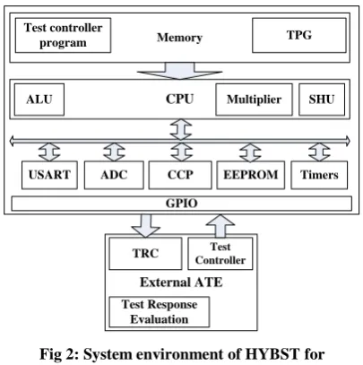
decision about tested microcontroller to go/no go. Figure 2 illustrates the proposed Hybrid-based self-testing concept, where test program is resided in the microcontroller’s flash memory.
Microcontroller
Memory
CPU
TPG
USART Test controller
program
ADC CCP EEPROM Timers
GPIO
External ATE
TRC
Test Response Evaluation
Test Controller
[image:3.595.65.268.117.321.2]ALU Multiplier SHU
Fig 2: System environment of HYBST for microcontrollers
Development of the HYBST is divided into four phases to build test subroutines for each of the microcontroller modules:
Phase A: Information extraction and modules identification.
Phase B: Modules operations, as well as instructions that excite component operations and instructions (or instruction sequences) for controlling or observing microcontroller registers.
Phase C: Operand selection.
Phase D: Test routines Development.
2.1
Information extraction and component
identification phase
This phase studies core features of two Microchip PIC microcontrollers carefully and divide it structurally into a number of main modules (CPU – Memory – Timers – Serial Port – Capture/ Compare/Pulse Width Modulation modules – GPIO – A/D converter) as shown in Table 1. Then it collects all available information on every module to be effectively tested. Microcontroller memories can be divided into (RAM – EEPROM – Flash Memory).
Table 1. Microcontroller key features
Key Features Microchip
®
PIC16F877
Microchip® PIC18F452
CPU High performance 8bit RISC
CPU FLASH Memory
(14-bit Word) 8K Word 32K Word Data Memory (Byte) 368 1536
EEPROM (Byte) 256 256
I/O Ports 5 I/O Port 5 I/O Port
Timers 3 4
Capture/Compare/PWM 2 2 Serial Communications USART USART
Multiplier - 8 × 8
ISA 35 inst. 75 inst.
2.2
Instruction selection phase
Based on the ISA of the microcontroller family, every module M has a set of operations OM that module M performs. IM,O was denoted to be the set of microcontroller instructions that, causes module M to perform operation O. It is evident that, for each module M, has at least one microcontroller instruction that, causes module M to perform operation O, i.e. IM,O ≠ Ø. Instructions that belong to the same set IM,O:
Have different observability properties since, when operation O is performed, the outputs of module M drive internal microcontroller registers with different observability characteristics.
Have different controllability properties since, when operation O is performed, the inputs of module M are driven by internal microcontroller registers with different controllability characteristics.
After identification of the set IM,O for every module operation an instruction I was selected from the set IM,O according to the following criteria:
Criterion 1: Discard instructions belonging to IM,O that, when operation O is performed, the outputs of module M do not propagate to an internal microcontroller register.
Criterion 2: Between instructions IA and IB belonging to IM,O, IA is ranked higher priority than IB if it requires a smaller instruction sequence to propagate the outputs of module M through the related internal microcontroller register to GPIO pins. This means that instruction IA is easily more observable than IB and it should be preferred over IB.
Criterion 3: If Criterion 2 ranks two different instructions IA and IB belonging to IM,O, have the same priority, then IA is ranked higher than IB if it requires a smaller instruction sequence to generate a specific test pattern at the internal processor register that drives the inputs of module M. This means that instruction IA is easily more controllable than IB and it should be preferred over IB. The above three criteria aim to the efficiency of test routines for single module. After completing this phase, test instructions were selected to construct an efficiently test subroutines to test each microcontroller module.
2.3
Operand selection phase
In this phase, based on brute force technique test pattern generation technique was chosen to test microcontroller modules exhaustively in order achieve high fault coverage and to avoid the using of high cost fault simulator. After selection of the appropriate Operands or test pattern generation technique, test program subroutines will be developed then will be downloaded to microcontroller's flash memory for testing with respect to both critical issues; memory utilization and test application time.
2.4
Test program development phase
Before beginning of the development phase, it must be noted that this methodology was proposed in order to be used for in field test. This restriction makes the program should go either two ways (Normal mode or test mode). Figure 3 shows the flow chart of the complete test program of the proposed methodology. As shown in Figure 3, the proposed methodology asks first, if the system is going to work in normal mode or in test mode. If normal mode was chosen then the system will do it predefined operation, and if it works in test mode the system will be prepared to work in test mode. In test mode the microcontroller need to receive an input selection from one of the microcontroller ports which will be used to select specific module to be tested. Other microcontroller ports are set to be output port to propagate test response to external ATE.Every test subroutine has its own strategy as will be illustrated.
The overall test process is outlined in the following:
Extract information about microcontroller modules, then for (each microcontroller module M) {
for (every operation o∈ OM) { Determine IM,O
Select I ∈ IM,O , using controllability and observability criteria Using instruction I, apply Exhaustive test patterns
Drive test response to propagate to GPIO
Collect and compact test response using external ATE }
}
Evaluate compacted test response using external ATE List 1: overall test process
Start
End
PORTA = 0x02
Test GPIO
Test mode or Normal mode?
Set A/D off Disable Interrupts Set PORTB,C and D as Output
Set PORTA as Input Read PORTA
Yes
PORTA = 0x04
PORTA = 0x06
Test CPU Test USART
Yes
No No PORTA =
0x08
Test Timers
Yes
No PORTA =
0x0A
Test Capture/Compare module
Yes
No
PORTA = 0x0C
Test PWM
Yes
No
PORTA = 0x0E
Test Flash Memory
Yes
No
PORTA = 0x10
Test EEPROM
Yes
No
PORTA = 0x12
Test RAM
Yes
No Normal Mode Run normal application
program
No
No
Yes
[image:4.595.71.524.249.494.2]Yes
Fig 3: Complete flow chart of the HYBST methodology for Microchip PIC microcontrollers
2.4.1
Memory Test
Information extraction phase shows that microchip microcontroller memories can be divided into (RAM – EEPROM – Flash Memory). Each one of these has its own test strategy.
2.4.1.1
Flash Memory Test
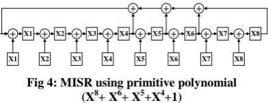
Flash memory test subroutine has been designed and implemented for both HYBST and SBST in order to check if the program has been downloaded successfully to the flash memory or not. Flash memory is tested by reading its data word by word and compact them using software MISR with primitive polynomial (X8+X6+X5+X4+1), shown in Figure 4. The resulted signature from the MISR is compared with the reference signature stored in EEPROM. The reference signature was generated by another C++ program (written on Visual Studio 2010 package). This program generates signature by reading Hex file data generated from the mikroC compiler for the test program and compact it using the same MISR. If both signatures are equal then program is successfully downloaded and memory is tested as well and
+ X1 + X2 + X3 + X4 + X5 + X6 + X7 + X8
X1 X2 X3 X4 X5 X6 X7 X8
+ + +
Fig 4: MISR using primitive polynomial (X8+ X6+ X5+X4+1)
2.4.1.2
RAM Test
[image:4.595.332.528.537.612.2]performing R0 then W1 on each cell, before continuing to the next cell. By arranging, a number of March elements one after the other, a March test is constructed. Because of their simplicity and linearity with the memory size, all of them are in a complexity of O (n). March test AB sequence is {↨(W0); ↑(R0;W1;R1;W1;R1);↑(R1;W0;R0;W0;R0);
↓(R0;W1;R1;W1;R1); ↓(R1;W0;R0; W0;R0); ↨(R0)}.
2.4.1.3
EEPROM Test
EEPROM test subroutine has been implemented here for both HYBST and SBST test techniques based on modified algorithmic test sequence (MATS) algorithm that detects all combination of stuck-at faults (SAF) in RAMs [20]. MATS test sequence is {↑(W0); ↑(R0,W1); ↑(R1)} where EEPROM is tested and the test response is sent to a certain GPIO pin to indicate if it pass test or not.
2.4.2
USART Test
Test subroutine for the Universal Synchronous Asynchronous Receiver Transmitter (USART) has been designed and implemented for both HYBST and SBST test methodologies. It sets the baud rate of the USART to 1200 bps first. Then, the test patterns (0x00 – 0xFF – 0x33 – 0xCC – 0x0F – 0xF0) are sent to the transmitter of USART (TX) and loop it back again through MAX232 chip or through short circuit to receive it from receiver of USART (RX). These test patterns are output to the PORTD and the signatures on each pin in the PORTD and the signatures on USART (TX) and USART (RX) (PIN RX and TX in PORTC) are measured using the external ATE.
The USART test process is outlined in the following:
Configure USART, then Loop {
Send data through transmitter pin Check for received data from receiver pin If (received data = sent data) then
Send received data to GPIO Else
Error and exit test
Change data and continue loop until test patterns are all Sent through transmitter pin
Collect and compact test response using external ATE }
Evaluate compacted test response using external ATE
List 2: USART test process
2.4.3
GPIO pins Test
GPIO allow the microcontroller to monitor and control other devices. To add flexibility and functionality to a device, some pins are multiplexed with an alternate function(s).In this test, GPIO pins are set to be output ports. The test subroutine sends exhaustive test patterns (zero (min) to 255 (max)) (all possible combinations) to these ports.
The GPIO test process is outlined in the following:
Configure GPIO pins to be output Data = 0
Loop {
Send data through all GPIO ports
Collect and compact test response using external ATE Data = Data + 1
If (Data = 255) then Exit loop }
Evaluate compacted test response using external ATE
List 3: GPIO test process
2.4.4
Timer Test
Information extraction phase shows that most of the microchip microcontroller families have more than one timer. These timers have different sizes (8 or 16 bits) and different presale. Each timer is tested in two different presale to ensure timer functionality.
The Timer test process is outlined in the following:
Configure Timer presale Enable timer interrupt Start timer
Set GPIO pin to high Loop {
Watch timer interrupt to check if over flow or not If (timer over flow)
Exit loop
Reset GPIO pin to low }
Evaluate ON time window on GPIO pin using external ATE Repeat this process but using different presale and apply it to all timers
List 4: Timers test process
2.4.5
CPU Test
The CPU is the brain of the device. It is responsible for fetching the correct instruction for execution, decoding that instruction, and then executing it. Test subroutine has been designed and implemented to test microcontroller's CPU for both HYBST and SBST test strategies based on divide and conquer test strategy as in [21] but using exhaustive TPG. Here, the test subroutine divides the CPU structurally into (ALU – SHU – Multiplier) and test each of these components functionally. Moreover, the instructions are not randomly chosen, but carefully crafted in order to deliver all test sets to the desired components. Control unit will not be tested as previous approaches, because it is already tested during CPU test.
The CPU test process is outlined in the following:
Extract information about CPU modules (ALU – SHU – Multiplier if exist), then
for (each CPU module MCPU) { for (every operation o∈OMCPU) { Determine IMCPU,O
Select I ∈ IMCPU,O, using controllability and observability criteria
Apply Exhaustive test patterns for all IMCPU,O Drive test response to GPIO
Collect and compact test response using external ATE }
}
Evaluate compacted test response using external ATE
List 5: CPU test process
2.4.6
Capture/Compare/PWM Test
Period 5KHz
[image:6.595.61.276.74.159.2]50% Duty cycle
Fig 5: PWM
The Capture/Compare/PWM test process is outlined in the following:
Configure CCP1 registers to work in compare mode Initialize timer1value and enable interrupt
Start timer Loop {
Watch timer1until reaching compare value If (timer1 = compare value)
Exit loop }
Evaluate CCP pin output using external ATE Repeat this process for CCP2
Configure CCP1 registers to work in PWM mode Initialize PWM1 duty cycle to 50% of 5 KHz clock Start PWM1
Watch PWM1 output using external ATE Delay for 2ms
Stop PWM2
Repeat this process for PWM2
List 6: CCP test process
3.
EXPERIMENTAL RESULTS
In order to compare between the proposed testing strategy and previous testing strategies, pure SBST techniques using both linear feedback shift register (LFSR) and multiple input shift register (MISR) as the software TRC techniques will be implemented. The effectiveness of the proposed methodology and the pure SBST methodologies will be evaluated on two 8-bit high performance RISC Microchip® microcontrollers (PIC16F877A and PIC18F452).
Microchip® PIC microcontroller instruction set includes most common instructions like load and store, arithmetic and logical operations, jump and branch instructions. It includes the following components: CPU which consists of (ALU, SHU and Multiplier), Timers, I/O ports, serial port, pulse width modulation modules and memory which include (Flash memory, Data memory and EEPROM). These components are fully controllable and observable data inputs and outputs. Test programs were prepared for testing all of these components individually and collected together into one program.
An exhaustive test patterns were used to increase fault coverage and to come over the problem of high cost fault simulator. Test program statistics such as Memory utilization (Data memory – Flash memory), Time consumption (number of clock cycles taken to finish test) and Testability of microcontroller modules (number of modules that can be tested) are presented in Table 1 and Table 2. These tables compare between the proposed methodology and SBST test strategy using two different compaction techniques on both Microchip® PIC16F877A and PIC18F452.
The proposed methodology achieves a significant amount of reduction on key test program statistics like the program size (Data memory – Flash memory) and test time consuming.
[image:6.595.306.550.106.751.2]methodology is greater than other SBST methodology due to the use of exhaustive test patterns also due to the increase of modules that can be tested. Performance enhancement can be shown in Table 3 and Table 4.
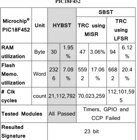
Table 2. Test Program Statistics for Microchip® PIC18F452
Microchip®
PIC18F452 Unit HYBST
SBST
TRC using MISR
TRC using LFSR RAM
utilization Byte 30
1.95
% 47 3.06% 94
6.12 %
Flash Memo. utilization
Word 232 6
7.09 %
559 2
17.06 %
668 2
20.4 %
# Clk
cycles count 21,112,792 70,023,259
112,101,59 5
Tested Modules All Passed Timers, GPIO and
CCP Failed
Resulted
Signature 23 bit
Table 3. Test Program Statistics for Microchip® PIC16F877
Microchip®
PIC16F877 Unit HYBST
SBST TRC using
MISR
TRC using LFSR RAM
utilization Byte 27
7.33
% 44
11.95
% 93
25.27 %
Flash Memo. utilization
Word 166 3
20.3 %
356 8
43.55 %
389 7
47.57 %
# Clk
cycles count 25,600,168 78,348,171
114,734,09 9
Tested Modules All Passed Timers, GPIO and CCP
Failed
Resulted
Signature 23 bit
Table 4. Performance enhancement using HYBST for Microchip® PIC18F452
Microchip® PIC 16F877
SBST TRC using
LFSR
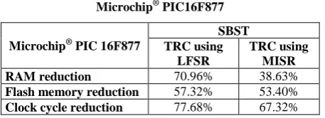
[image:6.595.311.548.133.376.2] [image:6.595.307.551.389.684.2]Table 5. Performance enhancement using HYBST for Microchip® PIC16F877
Microchip® PIC 16F877
SBST TRC using
LFSR
TRC using MISR RAM reduction 70.96% 38.63% Flash memory reduction 57.32% 53.40% Clock cycle reduction 77.68% 67.32%
It is evident that the proposed HYBST methodology is superior when compared to SBST methodologies with respect to:
RAM utilization.
Flash memory utilization.
Time consumption.
Number of tested modules where SBST cannot test all internal microcontroller modules, and cannot make sure that GPIO pin of the microcontroller work probably without using the external ATE.
Finally, it was found that the SBST is practically not suitable for the microcontroller testing, and the HYBST is more suitable for the microcontroller testing. In the next chapter, the integrated methodology of the microcontroller testing on the printed circuit board for fault detection and fault location (fault diagnosis) will be presented to indicate a real practical point of view of this method
4.
CONCLUSION
SBST has been proposed as an effective testing methodology for embedded systems with low or poor accessibility. But despite the significant advantages of SBST methodologies, it was found that, pure SBST methodologies is practically not the optimum solution to test on shelf microcontrollers with small memory because, it cannot test all microcontroller internal modules like timers, GPIO and CCP modules. Also, SBST uses a large space of memory for the software code that simulates TPG, BCU and TRC modules of the BIST system.
HYBST methodology has been proposed for on-shelf microcontroller devices that achieves high fault coverage with low hardware overhead and performance degradation. The methodology targets microcontroller components and applies exhaustive test patterns (operands) for every component operation. When compared with existing SBST methodologies, it requires much less computational effort while it achieves guaranteed high fault coverage.
Effectiveness of HYBST methodology has been demonstrated on both Microchip® PIC16F877A and PIC18F452 microcontrollers. The superiority of the proposed methodology in terms of test program size, memory requirements, and fault coverage is significant over SBST. Also, SBST methodology was demonstrated to be practically not suitable for in-field microcontroller testing, and the HYBST is more suitable for this process.
5.
REFERENCES
[1] International Technology Roadmap for Semiconductors, 1999 Edition.
[2] T.G.Foote, D.E.Hoffman, W.V.Huott, T.J. Koprowski, B.J. Robbins and M.P. Kusko, “Testingthe 400 MHZ IBM Generation-4 CMOS Chip”, in Proceedings of the
International Test Conference 1997, Washington DC., pp.106-114.
[3] G.Hetherington, T.Fryars, N.Tamarapalli, M.Kassab, A.Hassan and J.Rajski, “Logic BIST forlarge industrial designs: Real issues and case studies”, in Proceedings of the International Test Conference 1999, Atlantic City, NJ, pp.358-367
[4] Li Chen, S.Dey, “Software-Based Self-Testing Methodology for Processor Cores”, IEEE Transactions on CAD of Integrated Circuits and Systems, vo.20, no.3, pp. 369-380, March 2001.
[5] J. Shen and J. A. Abraham, "Native Mode Functional Test Generation for Processors with Applications to Self Test and Design Validation," Proceedings of the International Test Conference (ITC), pp. 990 – 999, 1998.
[6] D. Brahme and J. A. Abraham, "Functional Testing of Microprocessors," Proceedings of the IEEE Transactions on Computers, pp. 475 - 485, 1984.
[7] S. M. Thatte and J. A. Abraham, "Test Generation for Microprocessors," Proceedings of the IEEE Transactions on Computers, pp. 429 - 441, 1980.
[8] A. Hunger and A. Gaertner., "Functional Characterization of Microprocessors," Proceedings of the International Test Conference (ITC), pp. 794-803, 1984.
[9] H. Klug, "In Microprocessor Testing by Instruction Sequences Derived from Random Patterns," Proceedings of the International Test Conference (ITC), pp. 73-80, 1988.
[10]J. V. De-Goor, and O. Jansen, "Self Test for the Intel 8085," Proceedings of the Microprocessing and Microprogramming, pp. 165-175, 1990.
[11]J. V. De-Goor and Th. J. W. Verhallen, "Functional Testing of Current Microprocessors (applied to the Intel i860TM)," Proceedings of the International Test Conference (ITC), pp. 684 - 695, 1992.
[12]R. Velazco, C. Bellon, and H. Ziade, "Analysis of Experimental Results on Functional Testing and Diagnosis of Complex Circuits," Proceedings of the International Test Conference (ITC), pp. 64-72, 1988.
[13]G. Xenoulis, N. Kranitis, A. Paschalis, D. Gizopoulos, and Y. Zorian, "Application and Analysis of RT-level Software-Based Self-Testing for Embedded Processor Cores," Proceedings of the IEEE International Test Conference, pp. 431-440, 2003.
[14]A. Paschalis, N. Kranitis, D. Gizopoulos, and G. Xenoulis, "Software-Based Self-Testing of Embedded Processors," IEEE Transactions on Computers, vol. 54, pp. 461 – 475, 2005.
[15]A. Merentitis, N. Kranitis, G. Theodorou, D. Gizopoulos, and A. Paschalis, "Hybrid-SBST Methodology for Efficient Testing of Processor Cores," IEEE Design & Test of Computers, pp. 64-75, 2008.
[16]J. Zhou, "Software-Based Self-Test under Memory, Time and Power Constraints," PhD, Institute of Technology Computer Science, University of Stuttgart, 2009.
[18]M. H. El-Mahlawy, "A Novel Testing Method for Monostable Multivibrators," Proceedings of the 5th ICEENG Conference, Military Technical College, Cairo, Egypt, 2006.
[19]J. V. De-Goor and Z. Al-Ars, "Functional Memory Faults: A Formal Notation and a Taxonomy" Proceedings of the 18th IEEE VLSI Test Symp., PP. (281) - (289), 2000.
[20]M. S. Hamed, M. H. El-Mahlawy, M. H. Abd-El-Zeem, and I. Yossef, "FPGA Implementation of the BIST IP For SRAM Chips", Proceedings of the 6th ICEENG Conference, Military Technical College, Cairo, Egypt, 2008.