Low Truncation Error and Area Efficient Multiplier
for Cryptographic Applications
G.Umamaheswari,
PhD. Asst.Prof (Sr.Grade),Dept.of ECE, PSG College of Technology,
Coimbatore.
S.Shivkumar
Research Scholar, Anna University,
Chennai.
R.Deepika
Student, ME VLSI Design, Karpagam College of Engineering,
Coimbatore.
ABSTRACT
Multipliers play a vital role in many cryptographic applications like elliptic curve cryptography, RSA and other algorithms. The direct truncation of least significant part of the product leads to large error in the resultant product when fixed width output is the requirement. This paper proposes a truncation error minimizing logic which greatly reduces truncation error. Truncation error minimizing logic has been inserted in the least significant part of full length Baugh Wooley multiplier and Modified Booth Recoding multiplier and the results are compared.VHDL simulation shows that the truncation error is reduced up to 68% compared with direct truncated multiplier and involves lesser number of gates when compared to full length multipliers. It is also found that the total power consumed by these multipliers is only half the amount consumed by full length multiplier. Also Baugh Wooley multiplier performs better than Modified Booth Recoding multiplier.
General Terms
Fixed width multiplier, Vhdl modeling of truncation error minimizing logic.
Keywords
Fixed-width multiplier, Direct truncated multiplier, Baugh Wooley multiplier, Modified Booth recoding multiplier, Truncation error reduction logic, elliptic curve cryptography.
1.
INTRODUCTION
Multipliers play a very important role in many applications like cryptographic systems and multimedia. In full length multipliers, the number of partial products has to be reduced in order to avoid the growth of multiplication bit-width. Cutting off n- least significant bits (LSB) in the output results in a fixed-width multiplier with n-bit input and n-bit output [5]. However, truncating the entire LSB part leads to large truncation errors. In full-length multipliers error compensation techniques are precise but hardware is too complex and computation delay is high [2]. However, when the operand sizes of the multipliers and the process technology need to be changed, the existing multipliers have to be redesigned. In the proposed design, truncation error can be reduced by using “truncation error minimizing logic”. The error compensation circuit is constructed by the partial products terms with the most-significant weight in the least-significant segment [4]. The compensation vector can be directly injected into the fixed-width multiplier as compensation, so that extra compensation logic gates are not needed. By utilizing the symmetric property of truncation error minimizing logic, fan-in can be reduced to half and hardware can be shared [9]. Hardware complexity is reduced in this manner. As compared to other multipliers, the proposed fixed-width multiplier
performs with low compensation error and also with less hardware complexity.
Baugh-Wooley multiplier with error minimizing logic is compared with direct truncation multiplier. This shows that the Baugh-Wooley multiplier with the error minimizing logic requires lesser area since it involves lesser number of partial products. Also result shows that fixed-width multipliers with truncation error reduction circuit perform with lower truncation error when compared to other multipliers.
This paper is organized as follows. In Section 2, the Baugh-Wooley multiplier and Modified Booth Recoding multiplier are briefly reviewed. Section 3 describes the detailed description of Baugh-Wooley technique using truncation error minimizing logic. The experiment results and the comparisons are given in section 4. Section 5 concludes this paper.
2.
MULTIPLIERS
2.1 Baugh-Wooley Multiplier
Baugh-Wooley multiplication algorithm is an efficient way to handle the sign bits.Dr.Gebali has extended the basic idea and developed efficient fast products processors capable of performing double-precision multiply-accumulate operations without the speed penalty [11]. Baugh-Wooley Multiplier is used for both unsigned and signed number multiplication. Signed number operands are represented in 2’s complement form. Partial products are adjusted such that negative sign move to last step, which in turn maximize the regularity of the multiplication array [7]. Baugh-Wooley Multiplier operates on signed operands with 2’s complement representation to make sure that the signs of all partial products are positive. Let us consider two n-bit numbers, A and B, to be multiplied. A and B can be represented as in equation (i) and (ii). A=-an-12
n-1
+ i 2 i
(i)
B=-bn-12 -1+ i2i (ii)
Where the ai’s and bi’s are the bits in A and B, respectively,
and an-1 and bn-1 are the sign bits. The final product P=AxB is
given in equation (iii).
P=an-1bn-122n-2+ i j2i+j +2n-1 n-1ai 2i +
2n-1 n-1bj 2 j
+ [-22n-1] +2n (iii) Let us assume that A and B are 4-bit binary numbers, then the product P=AxB is 8-bits long and is given by equation (iv) P=a3b326+ i j2i+j+23 3ai 2i +23 3bj
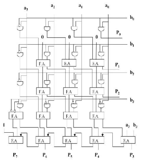
The block diagram of 4x4 Baugh-Wooley multiplier is given in fig 1.
Fig 1: Block diagram of a 4x4 Baugh-Wooley multiplier
Here a0, a1, a2, a3 and b0, b1, b2, b3 are the inputs. The outputs are p0, p1... p7. This will take less time to multiply large number of 2’s complement but less than 32 bit. Above 32 bit modified Baugh-Wooley multiplier is used[8].
2.2 Modified Booth Recoding
The Modified Booth (MB) algorithm [2] guarantees that only half the number of partial products will be generated, compared to a conventional partial-product generation using 2-input AND gates. The reduction of partial-product rows is achieved by encoding the multiplier into {-2,-1, 0, 1, 2}, which is then multiplied with the multiplicand. A Modified Booth multiplier therefore works, internally, with two’s complement representation of the partial products. To avoid sign extension of the partial products, we are using the scheme presented by Fadavi-Ardekani [3].In the two’s complement representation, a change of sign includes the insertion of a ‘1’at the least significant bit (LSB) position. To avoid an irregular implementation of the partial-product reduction circuitry, we draw on the idea called modified partial product array[4].Here ,the impact of LSB insertion on the two least significant bit positions of the partial product is pre-computed. The pre-computation redefines the LSB of the partial product [4] and moves the potential ‘1’, which results from the LSB insertion, to the second least significant position. The advantages of this technique are:
Only n/2 clock cycles are needed for n-bit multiplication as compared to n clock cycles in Booth’s algorithm.
Isolated 0/1 are handled efficiently.
For even n, the two’s complement multipliers are handled automatically whereas for odd n an extension of sign bit is required.
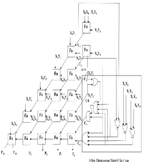
The block diagram of modified booth recoding multiplier is shown in fig 2.
Fig 2: Block Diagram of Modified Booth Recoding Multiplier
Partial Products are generated using modified booth’s recoding unit block. It can encode the digits by looking at three bits at a time. Booth recoding table must be able to add multiplicand times –2, -1, 0, 1 and 2.Since Booth recoding got rid of generating partial products is not that hard as shifting and negating.
The procedure to multiply two numbers is given below. For all odd values of i where i ranges from 1 to n-1
for n-bit multiplication (assuming n is even), the bits of the multiplicand are recoded using the formula
yi = xi-1 + xi-2 – 2xi
Then multiplication is done in normal way with the yi that have been calculated.
The following example illustrate the whole procedure:
A 01 00 01 17 X x 11 01 11 - 9
Y 01’ 10 01’ recoded multiplier -A +2A -A operation Add -A + 10 11 11
2 bit shift 1 11 10 11 11 Add 2A + 0 10 00 10 01 11 01 11 2 bit shift 00 01 11 01 11 Add -A + 10 11 11
Result 11 01 10 01 11 -153
[image:2.595.54.297.98.374.2]3.
BAUGH-WOOLEY TECHNIQUE
USING TRUNCATION ERROR
MINIMIZING LOGIC
[image:3.595.317.546.70.329.2]The full-length n-bit unsigned Baugh-Wooley partial product array can be divided into three subsets of most significant part (MSP), correction vector and least significant part (LSP). The first addition tree, which is devoted to lower weight partial products, is a standard one-counter constructed by using full adders and half adders. The lower weight partial products of correction vector include the most external four partial products, which are x5y0, x4y4, x1y4 and x0y5 in the 6-bit multiplier, having a weight of in error compensation. As for the second addition tree, it utilizes modified half adders (MHA) to take into account the contribution of partial products with higher weights. The higher weight partial products of correction vector include the other internal partial products, which are x3y2 and x2y3 in the 6-bit multiplier, having a weight in error compensation. The difference between MHA and standard HA is that when inputs of A and B are both 1, Sum=1 and Cout=1 as in MHA instead of Sum=0 and Cout=1 in standard HA. Fig.3 represents Truncation error minimizing logic before De Morgan simplification. This circuit is being inserted in the least significant part of full length Baugh Wooley multiplier after De Morgan simplification.
Fig 3: Truncation error minimizing logic before De Morgan simplification
The error compensation circuit is modified from the dual-tree design. To further reduce the compensation errors, IC is combined with error reduction circuit to correct the under-compensated and over-under-compensated cases [1]. To reduce hardware complexity, the half adders through C3 to Cn-2 is removed. In the under compensation cases of β=2, 4 and over compensation case of β=1, the compensation function is modified in Cn-1 and C n.
[image:3.595.61.270.353.528.2]In order to further reduce the circuit complexity, De-Morgan’s law is applied to simplify the error minimizing circuit in Cn-1 and Cn. After simplifying through De Morgan’s law and hardware sharing, the transistor count in proposed error minimizing circuit can be reduced from 62 to 40[9]. Finally, the proposed fixed-width multiplier with error minimizing logic is constructed and represented in fig 4.
Fig 4: Baugh Wooley multiplier with error reduction logic
4.
RESULTS
The proposed truncation error minimizing logic is designed in Xilinx 9.1i using VHDL code and simulated using Modelsim5.7.The Baugh Wooley Multiplier with error reduction circuit is compared with full-length Baugh Wooley multiplier and modified booth recoding multiplier to analyze its approximation error and hardware complexity. To analyze the compensation error, all possible input patterns are injected into the fixed-width multiplier. The truncated output and full-length multiplier output is compared.
4.1
Gate Counts
The number of gate counts for full length Baugh Wooley multiplier (FLBW) and Baugh Wooley multiplier with truncation error minimizing logic (BWTEM) are compared and is given in table 2. Also full length Modified Booth Recoding multiplier (FLMBR) and Modified Booth Recoding multiplier with truncation error minimizing logic (MBRTEM) are compared and tabulated respectively. Devices like Spartan2E and Spartan3E are used. Xilinx9.1i and Modelsim5.7 are used for simulation. The comparison results are shown in table 2. and table 3.
Table 2.Comparison of Gate Counts of FLBW and BWTEM
PARAMETERS FLBW BWTEM
No. of LUT’s 67 47
No. of Slices 36 26
No. of IOB’s 24 18
Gate Counts 402 291
Additional JTAG
[image:3.595.325.531.606.768.2]Table 3.Comparison of Gate Counts of FLMBR and MBRTEM
It is evident from the table 2 and table 3 that multipliers using truncation error minimizing logic requires lesser number of gates. It is also evident that Baugh Wooley multiplier using truncation error reduction circuit requires lesser number of gates when compared with modified booth recoding multiplier using the same error reduction circuit. Comparison of gates required by all the four multipliers is given in the figure 5.
[image:4.595.63.270.100.249.2]
Fig 5: Comparison of Gate Counts using various devices
4.2 Power Analysis
The power analysis of full length Baugh Wooley multiplier (FLBW),Baugh Wooley with truncation error minimizing logic (BWTEM),full length modified booth recoding multiplier and modified booth recoding with truncation error reduction logic (MBRTEM) are done at various frequencies. The results show that as frequency increases power also increases and the multipliers with truncation error reduction consumes less power when compared to multipliers without truncation error minimizing logic.
Comparison of total power consumed by FLBW and BWTEM multipliers and FLMBR and MBRTEM under various frequencies are presented in table 4 and table 5 . It is evident from the table 4. and table 5.that the multiplier using truncation error reduction circuit consumes lesser power than full length multipliers without error minimizing logic.
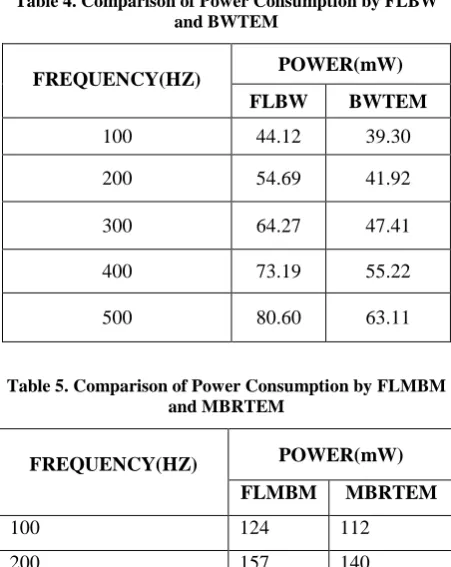
Table 4. Comparison of Power Consumption by FLBW and BWTEM
FREQUENCY(HZ) POWER(mW)
FLBW BWTEM
100 44.12 39.30
200 54.69 41.92
300 64.27 47.41
400 73.19 55.22
[image:4.595.62.286.357.533.2]500 80.60 63.11
Table 5. Comparison of Power Consumption by FLMBM and MBRTEM
FREQUENCY(HZ) POWER(mW)
FLMBM MBRTEM
100 124 112
200 157 140
300 192 177
400 219 193
500 254 236
It is also evident from the table 4. and table 5. that the Baugh Wooley multiplier using truncation error minimizing logic consumes less power when compared with Modified Booth Recoding multiplier using the same truncation error minimizing logic. The figure 6. represents the power consumed by FLBW, BWTEM,FLMBR and MBRTEM at various frequencies.
Fig 6: Comparison of Power Consumption by FLBW , BWTEM , FLMBR and MBRTEM
0 200 400 600 800 1000 1200
Spartan 2E
Spartan 3E
FLBW
BWTEM
FLMBR
MBRTEM
0 50 100 150 200 250 300
100 200 300 400 500
P
owe
r
in m
W
Frequency in Hertz
FLBW
BWTEM
FLMBR
MBRTEM PARAMETERS FLMBR MBRTEM
No. of LUT’s 51 96
No. of Slices 32 54
No. of IOB’s 21 18
Gate Counts 1240 681
Additional JTAG
[image:4.595.326.549.543.718.2]Figure 6 shows that Baugh Wooley and Modified Booth Recoding which uses truncation error minimizing logic consumes less power when compared with full length multiplier without error minimizing logic.
4.3 Comparison of Compensation Error
Percentage
[image:5.595.313.509.100.237.2]The truncation error minimizing logic is used to reduce the compensation error in Baugh Wooley multiplier and to reduce the hardware complexity. Some examples are given to prove that this compensation method results in less truncation error when compared to multipliers using direct truncation. In direct truncated multipliers truncation error increases because of truncating the entire LSB part of the multiplier output. Table 7. gives the results of direct truncated Baugh Wooley multiplier and Baugh Wooley multiplier with error reduction circuit for the given inputs of 6-bit multiplicand and multiplier and Table 8. gives the reduced results of direct truncated modified booth recoding multiplier and modified booth recoding multiplier with error reduction circuit for the given patterns of 6-bit multiplicand and multiplier.
Table 7. Truncation results of FLBW and BWTEM
This new error minimizing logic given is illustrated through an example given below.
Example 1
Reduction Error Value
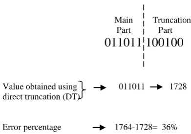
Full Length Baugh Wooley (Direct Truncation)
Main Truncation Part Part
011011 100100
Value obtained using 011011 1728 direct truncation (DT)
Error percentage 1764-1728= 36%
Baugh Wooley with Truncation Error Minimizing Logic
(Error reduction logic)
011011 100100
Adding MSB of truncation part to the main part gives the value 1792.011011 + 1
011100 1792
Reduced error percentage 1792-1764= 28%
Example 2
Reduction Error Value
Full Length BaughWooley (Direct Truncation)
Main Truncation Part Part
101011 111001
Value obtained using 101011 2752 direct truncation
Error percentage 2809-2752= 57%
INPUTS NUMERICAL
PRODUCT (XY)
REDUCTION ERROR VALUE
REDUCED ERROR
%
MULTIPLIER X
MULTIPLICAND Y
FLBW (DT)
BWTEM (ERL)
101010 101010 1764 36 28 8
110101 110101 2809 57 7 50
110101 101010 2226 50 14 36
111111 111111 3969 1 1 0
011001 110111 1375 31 33 2
AVG 35 16.6 18.4
Multiplicand
Multiplier
Product
101010 X 42
101010 42
011011100100 1764 Binary Decimal Value value
Multiplicand ddd
Multiplier
Product
110101 X 53
110101 53
101011111001 2809 228091764
[image:5.595.48.293.327.561.2]Baugh Wooley with Truncation Error Minimizing Logic
(Error reduction logic)
101011 111001
Adding MSB of truncation part to the main part gives the value 2816.
101011 + 1
101100 2816
Error percentage 2816-2809= 7%
[image:6.595.317.546.176.423.2]The proposed truncation error minimizing logic in which the product is split into two parts: with higher order bits grouped into main part and truncation part. The length of each part need not necessary be equal. The addition process starts from the demarcation line in which the most significant bit(MSB)of the truncation part (LSB) is being added to the least significant bit of the main part(LSB) . In the example 1, the 6-bit multiplicand “101010” (42) and 6-6-bit multiplier “101010” (42) is multiplied. This results in a product of 12 bits “011011100100” (1764). Full length Baugh Wooley multiplier using direct truncation the 6–bit LSB is being truncated directly which results in a value of “011011” (1728).This results in a error percentage of 36% from the original product. While using the error reduction circuit by adding the MSB of the inaccurate part to the LSB of the accurate part the he value obtained is “011100” (1764). This results in a error percentage of 28% from the original product.
Table 8. Reduced error value of FLMBR and MBRTER
The same procedure adopted in Baugh Wooley multiplier has been carried out in the Modified Booth Recoding Multiplier. It is evident from the tables that the Baugh Wooley multiplier
using Truncation error reduction(BWTER) circuit performs a higher percentage in error reduction when compared with Modified Booth Recoding multiplier(MBRTER) using the same truncation error circuit .
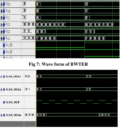
[image:6.595.48.292.495.715.2]Wave forms of Baugh Wooley multiplier using truncation error reduction circuit and Modified Booth Recoding multiplier using the same truncation error minimizing logic for the given inputs of 6-bit multiplicand and multiplier are shown in figure 7 and figure 8.
Fig 7: Wave form of BWTER
Fig 8:Wave form of MBRTER
5.
CONCLUSION
A fixed-width multiplier with a new error compensation circuit by using ‘truncation error minimizing logic” is proposed. Truncation error minimizing logic has been inserted in the least significant part of full length Baugh Wooley multiplier and modified booth recoding multiplier. In these multipliers the truncation error is reduced up to 68% as compared with direct truncated multiplier and it involves lesser number of gates (of about 47%) when compared to full length multipliers. Also the total powers consumed by these multipliers are only half the amount consumed by full length multipliers. Extensive comparisons among all the four multipliers show that Baugh Wooley multiplier with truncation error minimizing logic is the one which occupies minimum area and less power. This is because it uses lesser number of partial products. And also it reduces truncation error up to 68%. These fast multipliers play a very important role in cryptographic systems, multimedia, etc.
6.
REFERENCES
[1] S.S.Kidambi, F.El-Guibaly, and A. Antoniou, “Area-efficient multipliers for digital signal processing applications,” IEEE Trans. Circuits Syst. II, Exp. Briefs, vol. 43, no. 2, pp. 90–95, Feb. 1996.
[2] J. M. Jou, S. R. Kuang, and R. D. Chen, “Design of low-error fixed width multipliers for DSP applications,” IEEE Trans. Circuits Syst. II, Exp. Briefs, vol. 46, no. 6, pp. 836–842, June. 1999.
INPUTS NUMERICAL
PRODUCT (XY)
REDUCTION ERROR VALUE
REDUCED ERROR
%
MULTIPLIER X
MULTIPLICAND Y
FLMB R
MBRTER
001000 010111 184 59 8 51
110101 101010 2226 64 14 50
011110 011001 750 704 736 32
101110 101100 2024 40 24 16
011110 000100 120 56 8 48
[image:6.595.47.292.497.716.2][3] J.Fadavi-Ardekani,“MxN Booth Encoded Multiplier Generator Using Optimized Wallace trees,” IEEE Transactions on Very Large Scale Integration (VLSI) Systems, vol. 1, no. 2, pp. 120–125, June,1993.
[4] S. J. Jou and H. H. Wang, “Fixed-width multiplier for DSP application,” in Proc. IEEE Int. Symp. Comput. Design, pp. 318–322, Sept, 2000.
[5] F.Curticapean and J. Niittylahti, “A hardware efficient direct digital frequency synthesizer,” in Proc. IEEE Int. Conf. Electron., Circuits, Syst., vol. 1, pp. 51–54,Sept 2001.
[6] A.G.M. Strollo, N. Petra, and D.D.Caro, “Dual-tree error compensation for high performance fixed-width multipliers,” IEEE Trans. Circuits Syst. II, Exp. Briefs, vol. 52, no. 8, pp. 501–507, Aug, 2005.
[7] M.Badghare, S.K.Mangal, R.B.Deshmukh, R.M.Patrikar “Design of Low Power Parallel Multiplier”, Journal of Low Power Electronics, vol 5,pp 31-39 Number 1, April 2009.
[8] K.Z. Pekmestzi, "Complex Number Multipliers" IEEE Proceedings (Computers and Digital Technology), Vol. 136, No. 1, pp. 70-75, Jan, 1989.
[9] Y.-Y. Zhang, Z. Li, L. Yang, and S.-W. Zhang, “An efficient CSA architecture for Montgomery modular multiplication,” Microprocessors and Microsystems, vol. 31, no. 7, pp. 456 – 459, Nov, 2007.
[10] C. McIvor, M. McLoone, and J. McCanny, “Modified Montgomery modular multiplication and RSA exponentiation techniques,” in IEEE Proceedings of Computers and Digital Techniques, vol. 151, no. 6, pp. 402 – 408, Nov.2004.