Voltage Collapse Avoidance by using STATCOM
Champa Nandi
Assistant Professor Dept. of Electrical Engineering
Tripura University
Jhuma Rudra Pal, Tandra Sutradhar.
Dept. of M.Tech Electrical Engineering T.U. (A Central University)
ABSTRACT
This paper deals with modelling and simulation of STATCOM in IEEE 14 bus System with Induction Motor load for avoiding voltage collapse. Three Phases to ground fault is applied in predominant Induction motor load bus for voltage collapse analysis. The effect of Critical Fault Clearing Time [CFCT] of the system due to facing the fault, to prevent permanent voltage collapse has been analyzed with and without STATCOM. Simulations of the STATCOM were carried out by using Power System Computer Aided Design (PSCAD) software. Simulation results prove that the STATCOM is capable of mitigating voltage collapse with minimum clearing Time.
Keywords
STATCOM; Reactive power compensation; Voltage Collapse;CFCT;Stability.
1.
INTRODUCTION
Modern power systems are designed so as to improve the performance of an ac power system. We need to manage this reactive power in an efficient way and this is known as reactive power compensation. Two aspects to the problem of reactive power compensation are : load compensation and voltage support. Load compensation consists of improvement in power factor, balancing of real power drawn from the supply, better voltage regulation. Voltage support consists of reduction of voltage fluctuation at a given terminal of the transmission line. Two types of compensation can be used: series and shunt compensation. The jobs of absorbing or generating reactive power with a faster time response come under Flexible AC Systems (FACTS).An increase in transfer of apparent power through a transmission line, and much better stability by the adjustment of parameters that govern the power system i.e. current, voltage, phase angle, frequency and impedance. It is essential to balance the supply and demand of Active and Reactive power in a power system. If the balance is lost the system frequency and voltage excursion may occur resulting, in worst case, in the collapse of the power system. The increase in the loading of the transmission
power electronic-based and other static Controllers to enhance controllability and increase power transfer capability" There are two generations for realization of power electronics based FACTS controllers: the first generation employs conventional thyristor-switched capacitors and reactors, and quadrature tap-changing transformers, the second generation employs gate turn-off (GTO) thyristor-switched converters as voltage source converters (VSCs) Static Synchronous Compensator (STATCOM). STATCOM is one of the advanced technologies of power electronics system known as FACTs Controller, which provides fast and continuous capacitive and inductive reactive power supply to the power system.[1][2][3]
2.
STATCOM
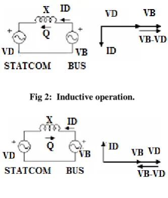
[image:1.595.342.519.509.692.2]Fig 2: Inductive operation.
Fig 3: Capacitive operation.
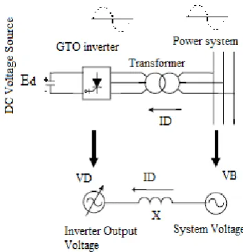
During No load mode, VB = VD, ID = 0.The reactive power is zero and the D-STATCOM does not generate or absorb reactive power.
During Inductive mode of Operation ID appears to be lagging current, since the magnitude of the current can be controlled by adjusting VD. The STATCOM will function as a reactor whose inductive reactance is continuously controllable. The current (ID) flows through the transformer reactance from the AC system to STATCOM device. The device generates Inductive reactive power.
During Capacitive mode of Operation ID appears to be leading current, Since the magnitude of the current can be controlled by adjusting VD. The STATCOM will function as a capacitor whose capacitive reactance is continuously controllable. The current (ID) flows through the transformer reactance from STATCOM device to the AC system. The device generates capacitive reactive power. [1][4]
In an inductive circuit, we know the instantaneous power to be ………(1)
……….. (2)
Instantaneous power is
Where, V max = Peak value of the voltage waveform; Imax = Peak value of the current waveform; = Angular
frequency=2πf, where f is the frequency of the waveform; t = Time period; = Angle by which the current lags the voltage in phase.
3.
CONTROLLER CONFIGURATION
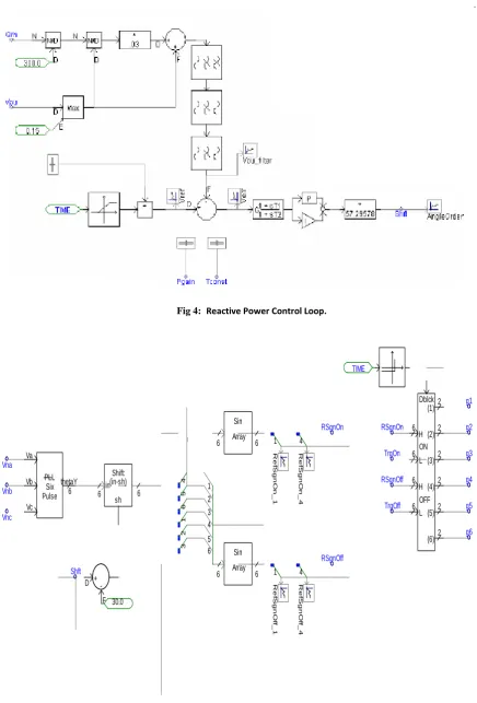
Fig 4: Reactive Power Control Loop. g1 1 g1 2 TIME g2 1 g2 2 g3 1 g3 2 g4 1 g4 2 g5 1 g5 2 Va Vb Vc PLL Six Pulse 6 thetaY Vnc Vnb Vna Sin Array
6 6 1
R e fSg n O n _ 1 4 4 5 6 1 2 3 1 2 3 4 5 6 Sin Array
6 6 1 4
[image:3.595.71.494.74.345.2]Fig 6: PWM carrier generation.
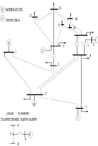
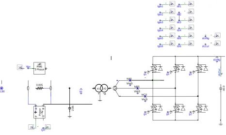
Fig 7: IEEE 14 bus system with interconnected STATCOM compensator.
4.
SIMUILATION AND DESCRIPTION
Fig 7. STATCOM device in
5.
RESULTS AND DISCUSSION OF
RESULTS
5.1
Angle Order
The output of PI controller is the angle order, which is used to maintain the phase shift. The reactive power flow from the system is compared to the reference per-unit voltage that contributes to a change of the phase shift. The difference in phase shift will provide the needed reactive power from the DC capacitor.
5.2 Compensated Reactive Power
At the distribution level, it is used to improve the power factor and support the voltage of large industrial loads. This is particularly crucial in situations where some fault appears in the grid. In such a situation, it will often be a matter of milliseconds for the Reactive Power Compensator, i.e. the FACTS device, to go into action and help restore the stability, and the voltage of the grid, in order to prevent, or mitigate, a voltage collapse. 0.005 VnaS NAS VnbS NBS VncS NCS dcCur Idi1 dcVltg g1 g2 g3 g4 g5 g6 1 2 d cC u r 3 2 5 2 4 2 6 2 2 2 dcVltg Igto4 Idi4 Igto1 Igto3 Igto6 Igto5 Igto2 Qm Vpu Idi2 Idi3 Idi5 Idi6 Po w e r A B P Q 3 Phase RMS Vn 4 0 .0
TL88 #1 #2
2
.8
5
Phase shift
time(... 0.0 1.0 2.0 3.0 4.0 5.0 ...
... ... -40 -30 -20 -10 0 10 20 d e g re e AngleOrder
reactive pow er
time(... 0.0 1.0 2.0 3.0 4.0 5.0 ...
... ... -50 0 50 100 150 200 250 300 350 400 M v a r Q
[image:5.595.67.534.70.349.2] [image:5.595.58.279.518.662.2]5.2
Voltage Collapse Case
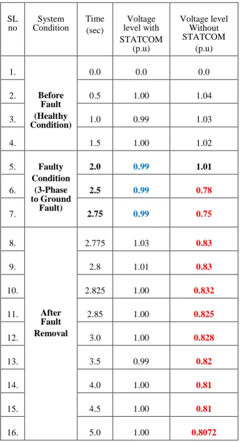
Table: Comparative Voltage Level (at Bus 6) of IEEE 14 Bus Systems
The main symptoms of voltage collapse are – low voltage profiles, heavy reactive power flows, inadequate reactive support, and heavily loaded systems. it is seen that without FACTS controllers the voltage level enters in voltage instability zone even if the fault is cleared. But due to presence of a STATCOM this type of instability can be avoided.
[image:6.595.48.287.153.592.2].
Fig 11: Voltage characteristics graphs during voltage collapse
5.4 Critical Fault Clearing Time [CFCT]
It is cleared that the critical fault clearing time is important to ensure stable operating voltage for the Induction Motor predominant load buses. The critical clearing time for the system to regain voltage at stable state
5.2.1
With the Presence of STATCOM is 46 msec.5.2.2
Without the STATCOM the system have not comesback to its original operating voltage level.[9]
Fig 12: Voltage characteristics graphs during voltage collapse
6.
CONCLUSION
The control strategy for the STATCOM is the AC side voltage or reactive power control. The IGBT’s are connected inversely and parallel to the diodes for commutation purposes and to charge the capacitor. IGBTs are used in this simulation because it is easy to control the switch on and off of their gates and suitable for the designed STATCOM. From the simulation results, the construction designed STATCOM responded well in mitigating voltage collapse caused by three-phase balanced fault. The DC capacitor value is dependent on the percentage of voltage sag. The difference of step drop load current during sag is the amount of reactive current needed to be compensated. Hence STATCOM is a promising device in power systems for mitigating power quality related problems. SL
no
System Condition
Time (sec)
Voltage level with STATCOM
(p.u)
Voltage level Without STATCOM
(p.u)
1.
Before Fault (Healthy Condition)
0.0 0.0 0.0
2. 0.5 1.00 1.04
3. 1.0 0.99 1.03
4. 1.5 1.00 1.02
5. Faulty Condition
(3-Phase to Ground
Fault)
2.0 0.99 1.01
6. 2.5 0.99 0.78
7. 2.75 0.99 0.75
8.
After Fault Removal
2.775 1.03 0.83
9. 2.8 1.01 0.83
10. 2.825 1.00 0.832
11. 2.85 1.00 0.825
12. 3.0 1.00 0.828
13. 3.5 0.99 0.82
14. 4.0 1.00 0.81
15. 4.5 1.00 0.81
[image:6.595.316.544.375.526.2]7.
REFERENCES
[1] Abu-Siada, Chatura Karunar, “Improvement Of Transmission Line Power Transfer Capability, Case Study”, Electrical and Electronics Engineering: An International Journal (EEEIJ) Vol.1, No.1, May 2012. [2] Hendri Masdi, Norman Mariun, S.M. Bashi, Azah
Mohamed, Sallehhudin Yusuf,” Construction of a Prototype D-Statcom for Voltage Sag Mitigation “European Journal of Scientific Research ,ISSN 1450-216X Vol.30 No.1 (2009), pp.112-127
[3] S.HADJERI, Fatiha GHEZAL ,S.A.ZIDI, ” Simulation of a three level 48 pulses Statcom ” 2008-Mediamira science Publisher. Volume 49, Number 2, 2008.
[4] S.H. Hosseini, R. Rahnavard, Y. Ebrahimi, ”Reactive Power Compensation in Distribution Networks with STATCOM by Fuzzy logic Theory Application”,5th
International Power Electronics and Motion Control
Conference (IPEMC), Shanghai, China, 14-16August 2006 (CD).
[5] S.H. Hosseini, R. Rahnavard, ”Comparison of Two Methods for Shunt Active Power Filter under the Distorted Source Voltages Condition” ,ECTI-CON, Rachthani, Thailand, pp. 9-13, Rachthani, 10-13 May 2006.
[6] S.Sundeep, Dr. G. Madhusudhana Rao,” Modelling and Analysis of Custom Power Devices for Improve Power Quality”, International Journal of Electrical and Computer Engineering (IJECE),Vol.1, No.1, September 2011, pp. 43~48, ISSN: 2088-8708.