Facial Image Morphing for Animation using Mesh
Warping Method
D B Shirore
Department of Electronics and Telecommunication Engineering (PG Student)
Late G N Sapkal College of Engineering Nasik, India
S R Baji
Department of Electronics and Telecommunication Engineering (Faculty of Engineering) Late G N Sapkal College of Engineering
Nasik, India
ABSTRACT
Image morphing is used to provide visual effects in television and film. Image Morphing derives from the word Metamorphosis, means change shape and size of an image. Transition of one object to another is termed as Morphing. This is an animation technique which metamorphoses the first image into the second image. The morphing technique has two steps: firstly it warps two images to have same shape and in second step it cross dissolves resulting images. The warping is 2-D geometric transformation of image, when applied, it generates a distorted image and cross-dissolving means color transformation. This paper uses mesh warping technique to build a framework of image based morphing of facial animation with low complexity. Image morphing is implemented using MATLAB software, which uses some digital images which are captured from camera. After morphing process, the program will output N number of images. These images are used together into a short animated sequence.
General Terms
Viola Jones Algorithm, feature (control) points, image partitioned, Mesh Warping.
Keywords
Image Morphing, Distorted, Faded, Mesh Warping, Cross dissolving.
1.
INTRODUCTION
Image morphing technique is used for digital image processing and as animation tool [2]. Morphing of images is continuously evolving and becoming a challenging field in data security and information hiding [2].
It is a special technique which smoothly transforms one graphical object into some other object and it animates over some period of time [1].
Before the image warping process was known, image morphing was done with the help of the cross-dissolving of images, where one image is faded out and other image is faded in. This method was not so effective in signifying the metamorphosis. In addition to this, during face image morphing the double exposure effect in the eyes and mouth
areas is seen and morph does not look natural. Three steps are involved in getting effective and smooth transformation of images [6].
1. Extracting control points
2. Warping source image according to destination image
3. Color transition methods to blend colors
Landmarks or control point extraction is first and most important step; these extractions will be used when image warping takes place. Image warping is nothing but a method for deformation of a digital image to different shape. Color transition method will blends the warped image color with other one, it will transform one image into another [8].
In color transition, each pixels color from first image is interpolated to the corresponding second image pixel value [10].
Morphing is also used in medical imaging field for recovering features which are not visible in images by finding relative features among multiple pair of scanned images. Morphing is widely used in gaming industry, movie animations, multimedia projects, educational and computer based training. Advanced morphing techniques used by film makers from Hollywood to generate special effects [11]. For speeding production, even Disney animations are made using morphing. There are very few efficient techniques are available for generating face morphing, because of which this domain sees increased research interest [11].
2.
PROBLEM DEFINITION
This paper represents development of an Image Morphing software application by using MATLAB, which helps in morphing images. As morphing is the process by which one image smoothly transforms into another. The mathematical formulas are used to calculate intermediate images from the source and target images. Mesh Warping Method is used to implement image morphing.
3.
METHODOLOGY
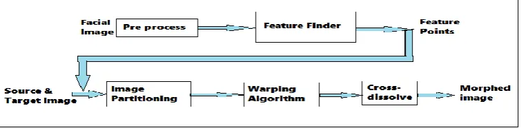
[image:1.595.111.492.659.752.2]The algorithm has two main components namely, Feature finder and a Face morphing. The following fig. 1 shows image morphing procedure
3.1
Pre-Processing
Morphing of facial image is developed by using MATLAB software. In morphing process one picture smoothly transmits into another. Before morphing process is always better to do some pre-processing like resizing and enhancing image. Image resize at a fixed value 256*256 as well as it is enhanced by using median filter.
3.2
Feature Finding
Viola-Jones Algorithm from Matlab is used to detect feature points. It detects feature points such as faces, noses, eyes, mouth, or facial upper body. The competitive object detection rates in real time were research by Viola–Jones object detection framework. This framework can be trained to detect a variety of object classes, but primarily it was motivated for the problem of face detection. The feature provided by the detection framework is nothing but the sums of image pixels within that rectangular area of image. The features used by Viola-Jones framework all depend on more than one rectangular area, which are generally more complex. The value of any given feature is equal to the sum of the pixels within rectangles. Rectangular features of the facial image are rather primary when compared to other filters such as steerable filters. Although they are tender to vertical and horizontal features, their feedback is mostly rough. However, rectangular features can be calculated inconstanttime, with the help of an image representation known as the integral image, which gives them speed advantage. Because each rectangular area in a feature is mostly contiguous to at least one other rectangle, it shows that any two-rectangle feature can be calculated in six array references, any three rectangle feature in eight array references, and any four-rectangle feature in just nine references.
3.3
Image Partitioning
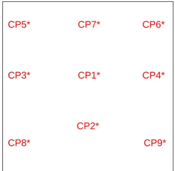
Our feature finder detects facial features such as eyes, nose and mouth. Based on this, we calculate control points on facial image. From calculations 4 control points are found, they are centroid of both eyes, centroid of mouth and edges of left and right eye. Beside these facial features if image, the edges of the face also need to be considered in the morphing algorithm. If the face edges are not match well in the morphing, the morphed image will look like strange image on the face edges. After this four control points 5 more feature points are calculated around the face edge they are four corners of face edge and one is centriod of forehead. Hence, total 9 control points are calculated for each face as shown in fig. 2.
CP5* CP7* CP6*
CP3* CP1* CP4*
CP2*
[image:2.595.354.520.127.309.2]CP8* CP9*
Fig 2: Detection of Control point
[image:2.595.76.257.575.752.2]Based on these 9 control points, image is partitions each photo into 16 non-overlapping quadrangular regions. Fig. 3 shows partitioning of image in binary form. Ideally, if we could detect more feature points automatically image partition into finer meshes, and the morphing result will be in proper form
Fig.3: Partitioned Image in Binary form
Since the control points of images are generally at different positions. In morphing process of source and target images, the both images have to be warped and hence their feature points are matched. Otherwise, the morphed image will contain four eyes, two mouths, and so forth. It will looks very strange and unpleasant that way.
3.4
Mesh Warping
The mesh warping algorithm, features with quadrangular meshes in the source and target images. Small regions are formed by breaking images, these regions are mapped onto each other for morphing.
The source image associated with mesh. It specifies the coordinates of landmarks or control points. A second mesh specifies their relative positions in the target image.
Meshes of source and target images are shown overlaid on source image and target image in the upper left and lower right images. Notice that landmarks such as the, lips, eyes and nose in both meshes lie below the corresponding grid lines. Together, meshes of source and target images are used to define the spatial transformation that maps all points in source onto target. The meshes are constrained to be topologically equivalent.
Fig 4: Quadrangles in Warping Process of (a) Source image (b) Target image
[image:2.595.324.527.587.662.2]resizing of L1 of ABCD quadrangle takes place and it became 8. Similarly there is resizing of L1 of PQRS quadrangle takes place and it became 5.
3.5
Cross Dissolving
The Cross-dissolve is a useful color transformation. Given two images of f(z,y) and g(z,y), a cross-dissolve between them is a group of transformations of the image color space.
After coordinate transformations for each of the two facial images are performed, the feature points of these images are matched. i.e., the left eye in one image will be at the same position as the left eye in the other image. To complete face morphing, there is need to do cross-dissolving as the coordinate transforms are taking place. Cross dissolving is described by the following Equation
.
C(x, y) = αA (x, y) + (1−α) B (x, y) For 0 ≤ α ≤1
Where A, B are the pair of images, and C is the morphing result. This operation is performed pixel by pixel, and each of the color components RGB is dealt with individually. Quantitative Measure to study the effect of morphing is Computing Total Energy of Face Component. To compute the total energy of each face component, the first step is to compute energy related to the color intensity, Energy related to the edges, and energy related to the locations. Then, there is combine those three energy values to obtain the total energy.
1) Energy Related to Color Intensity (C) 2) Energy Related to the Edges (E) 3) Energy Related to the Locations (D) 4) Total Energy of the Mapping
3.6
Methodology Flowchart
[image:3.595.320.537.154.279.2]The following figure 5 shows flowchart of system.
Fig 5: Flowchart of Methodology
4.
RESULT AND DISCUSSION
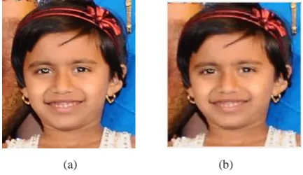
Experimental Results are obtained successfully by implementing mesh warping algorithm. Image 1 shows original image that is source image which we have to morph according to target image, before morphing it is need to do pre processing such as resizing image to a fixed value and enhanced image by using median filter.
(a) (b)
Image 1: Result of pre-processing: (a) Original Image (b) Pre-processed image
Image 2 shows feature finder results obtained by using Viola-Jones algorithm from Matlab. Using it, facial feature points are detect people faces, noses, eyes, mouth, or upper body. It forms 5 bounded boxes for eyes, nose, mouth and face.
Image 2: Feature Finder
Image 3 shows result of Image partitioned obtained by detecting 9 control points from feature finder and partitioned image into 16 non-overlapping quadrangle region.
[image:3.595.318.541.537.662.2]
(a) (b)
Fig 3: Result of Image Partitioning. (a) Detected control Points (b) Partitioned Image
Image 4: Output window of Image morphing of human faces
Image 5 shows sequence of output images. First row contains source image warped according to target image from left to right. Second row contains target image warped according to source image from right to left. And third row contains mixing of first and second row images.
Image 5: Cross-Dissolving output sequence of 2 intermediate images
Image 6 shows cross dissolving output sequence. It gives color transformation. In first row, first image is source image while in second row last image is target image. In between these two images we get 14 intermediate images which shows animation between two images.
Image 6: Cross-Dissolving output sequence of 14 intermediate images
Similarly, we can perform morphing operation for animal and human faces too. And we get morphed output as following image 7, 8, and 9.
Image 7: Output window of Image Morphing of animal and human faces
Image 8: Cross-Dissolving output sequence of 2 intermediate images between animal and human
Image 9: Cross-Dissolving output sequence of 14 intermediate images between animal and human
Similarly, we can perform morphing operation for animal and human faces too. And we get morphed output as following image 10, 11 and 12.
Image 10: Output window of Image morphing between two animal faces
Image 12: Cross-Dissolving output sequence of 14 intermediate images between two animal faces
5.
CONCLUSION
Image morphing is implemented with the help of mesh warping method. A few easily attributes, such as visual quality of morph, the ease with which the animator can select features such as eyes, nose and mouth with the help of our implemented paper. The algorithms we used were fast and instinctive, which accurately computed the mapping of each pixel from the source image to the destination image. The mesh was formed of quadrangles obtained from the specified 9 control points. This quadrangular meshes are plays very important role in warping process. These meshes are warped according to target image if it is source image and vice versa. Mesh Warping breaks images into small region and maps pixel to pixel from source to target image
.
Thus it is easy to matched eyes, mouth, nose & edges of upper body. In cross dissolve technique first frame is always source image and last frame is always target image and numbers of intermediate images are created. We have noticed in it that more the numbers of frames better were the morphed results and animation is easily created. We found that, to get best results Mesh Morphing is an effective technique.6.
ACKNOWLEDGMENTS
I take this opportunity to express my heart-felt gratitude to my guide, Prof. S .R. Baji , for her constant encouragement, wonderful technical guidance and support throughout the course.
I sincerely thank Prof. Bagal S. B., HOD of Electronics & Telecommunication Department for his advice and support during course of this work.
I express my thanks to all teaching & non- teaching staff of Electronics & Telecommunication Department for their kind co-operation and guidance for preparing and presenting this seminar.
I take this opportunity to express my gratitude towards my parents and my friends. Without which it would have not been possible.
7.
REFERENCES
[1] Urvshi Bhushan, Dr. G.P.Saroha and Disha Tivari, “An implemention of image morphing through mesh morphing algorithm”, Journal of Computer Science, vol. 2, issue 7, pp. 74-76, Jul. 2012.
[2] Bhumika H. Bhatt, Hita M. Joshi, “Feature based Image Morphing”, International Journal of Computer Science & Technology, vol. 2, issue 3, pp. 46-47, sept. 2011.
[3] Jennisa Areeyapinan, Pizzanu Kanongchaiyos, “Face Morphing Using Critical Point Filters”, international joint conference on computer science and software engineering, volume 9, pp.283-288, 2012
[4] Mayumi Yuasa and Osamu Yamaguchi, “Real-time Face Blending by Automatic Facial Feature Point Detection” 2008 IEEE
[5] Model Yongsheng Tang, MingXu, Zhenxiang Cai, “Research on Facial Expression Animation Based on 2D Mesh Morphing Driven by Pseudo Muscle Model” 2010 International Conference on Educational and Information Technology, volume 2 pp. 403-407, 2010
[6] George Wolberg, „Recent Advances in Image Morphing‟, Computer Graphics International‟96, Pohang, Korea, pp. 64-71, June 1996
[7] Alexandru Vlad Feciorescu, “Image Morphing Techniques”, JIDEG, VOLUME 5, pp.25-28 JUNE 2010
[8] Stephen Karungaru, Minoru Fukumi and Norio Akamatsu, “Automatic Human Faces Morphing Using Genetic Algorithms Based Control Points Selection” International Journal of Innovative Computing, Information and Control vol.3, no. 2, pp. 247 - 256, 2007.
[9] Wolberg G. “Digital Image Warping”, IEEE Computer Society press, Los Alamitos, CA, 1990
[10] Beier, T. and S. Nelly, Feature-based image metamorphosis, Proc. of the SIGGRAPH, pp.35-42, 1992.
[11] Aleandru Vlad FECIORESSCU, “Image Morphing Techniques,” Journal of Industrial Design and Engineering Graphics, vol.5, issue 1, pp. 25-28, Jun. 2010.
[12]Daw-Tung Lin and Han Huang, “Facial Expression Morphing and Animation with LocalWarping Methods”, National Science Council. Taiwan
[13]Digital Image Processing Jayaraman, S. Esakkirajan, T. Veerakumar pp.368-400