Inclusion behaviour in the liquid core during continuous
casting.
JIANG, Guang S.
Available from Sheffield Hallam University Research Archive (SHURA) at:
http://shura.shu.ac.uk/19876/
This document is the author deposited version. You are advised to consult the
publisher's version if you wish to cite from it.
Published version
JIANG, Guang S. (1992). Inclusion behaviour in the liquid core during continuous
casting. Doctoral, Sheffield Hallam University (United Kingdom)..
Copyright and re-use policy
See
http://shura.shu.ac.uk/information.html
Sheffield Hallam University Research Archive
Sheffield Hallam University
ProQuest Number: 10697182
All rights reserved
INFORMATION TO ALL USERS
The quality of this reproduction is dependent upon the quality of the copy submitted.
In the unlikely event that the author did not send a com plete manuscript and there are missing pages, these will be noted. Also, if material had to be removed,
a note will indicate the deletion.
uest
ProQuest 10697182
Published by ProQuest LLC(2017). Copyright of the Dissertation is held by the Author.
All rights reserved.
This work is protected against unauthorized copying under Title 17, United States C ode Microform Edition © ProQuest LLC.
ProQuest LLC.
789 East Eisenhower Parkway P.O. Box 1346
INCLUSION BEHAVIOUR IN THE LIQUID CORE
DURING CONTINUOUS CASTING
GUANG SHENG JIANG
A thesis submitted in partial fulfilment of the
requirements of the Council for National Academic Awards
for the degree of Doctor of Philosophy
M arch 1992
Sheffield City Polytechnic in collaboration with the
ACKNOWLEDGEMENTS
I am greatly indebted to the following for their help and
friendship I have recieved during the course of completion of the
thesis:-SERC for the financial support;
Professor A. W. D. Hills for his continuous guidance,
encouragement, receptivity and contagious enthusiasm for the
subject, and who, as a supervisor, has a great share of the author’s
acknowledgements concerning this work as a whole;
Mr. N. Dzmeiko for his continuous help and assistance
throughout all the experimental work;
Dr. I. G. Davies, who has very kindly welcomed author’s
requests for assistance and advices;
Mr. D. Latimer for his guidance and friendship throughout my
three-year stay at Sheffield City Polytechnic, and to all of his
staff in the Process Section for their assistance;
Mr. P. Fisher and the staff at the Photographic Unit for the
photography;
Mr. T. Reynolds, Mr. R. Hill and colleagues at Davy Distington
Ltd for their support and assistance at the final stage of the work.
Technicians, secretaries, Librarians, Lecturers, and other
staff members at Sheffield City Polytechnic for their prompt and
efficient services;
The research assistants, my fellow students, in the department
for their help at various stages of the work.
For the evidence of their help, it is all there in the thesis.
And finally to my wife Xiumei for her patience, understanding
and untiring support through it all.
INCLUSION BEHAVIOUR IN THE LIQUID CORE
DURING CONTINUOUS CASTING
by Guang Sheng Jiang
ABSTRACT
Water models using perspex have been built to study the fluid flow and
recirculation patterns developed in the sump of a steel continuous casting
machine and the influences these have on the behaviour of inclusions. An
experimental method has been devised to simulate the behaviour of inclusions in
the sump and to study the apportionment of the input flux of inclusions between
the molten mould powder layer and the strand. The method entails the uses of
finely dispersed coloured paraffin oil in the inlet stream together with a
floating colourless paraffin layer on the top of the water in the model mould to
simulate the molten powder layer on top of the molten steel.
A theoretical model has been formulated which relates the inclusion separation
in the sump to the fluid flow there. The inclusion removal ratio in the sump
for a given continuous casting machine can be predicted using this theoretical
model. The model, using the properties of liquid steel and practicable
casting speeds, demonstrates that the removal of inclusions of small size
( < 40 pm) from the mould sump is less than 5% efficient.
Inclusion agglomeration plays an important role in inclusion removal. It has
been shown that deep submersion of the SEN enhances the agglomeration of
inclusion particle. Under certain conditions, for example, the average particle
diameter in the meniscus region has been found to be as much as three times its
value at the SEN nozzle.
The use of fine alumina flakes or small air bubbles, together with a plane light
source, has been found to be very successful in studying the fluid flow patterns
developed in three-dimensional models. Employing this method, the fluid flow
patterns developed on different planes within the model mould have been viewed
and recorded photographically. The photographs so obtained have helped to
explain the results obtained for the removal of inclusions. The fluid flow
patterns developed when small outside diameter nozzles with deep SEN submerged
depths are used have been found to be of benefit to the removal of inclusions.
Increasing the SEN submerged depth promotes inclusion agglomeration and hence
increases the inclusion removal ratio. Reducing the nozzle outside diameter and
the casting speed increases the inclusion removal ratio in the sump. But the
infleunces of these latter changes are not very strong, so that inclusion
removal consideration need not influence the design strategies used for the
casting speed and nozzle outside diameter. The SEN port angle has a little
effect on the inclusion removal when using deep SEN submerged depth.
Although argon stream introduced into the tundish nozzle stream can protect the
nozzle blockage, it is not beneficial to the inclusion removal in the sump.
CONTENTS
page
ACKNOWLEDGEMENTS 0.3
ABSTRACT 0.4
LIST OF SYMBOLS 0.9
LIST OF TABLES 0.15
LIST OF FIGURES 0.18
LIST OF PLATES 0.24
1 INTRODUCTION
1.1 Foreword 1:1
1.2 The objective of the investigation 1:1
to 1:2 2 LITERATURE SURVEY
2.1 General overview 2:1
2.1.1 Development of continuous casting 2:1
2.1.2 Quality requirements for the continuously
cast products 2:2
2.2 Fluid flow patterns 2:2
2.2.1 Empirical approach 2:3
2.2.1.1 Experimental methods 2:3
2.2.1.2 Water modelling 2:5
2.2.1.3 Radioactive tracer studies 2:16
2.2.2 Theoretical approach 2:16
2.2.2.1 Mathematical model 2:17
2.2.2.2 Methods of solving mathematical models 2:20 2.2.3 Factors affecting the fluid flow patterns
within the mould 2:22
2.2.3.1 Effect of mould and SEN geometries 2:22 2.2.3.2 Effect of the casting speed and
the cooling rate 2:22
2.2.3.3 Effect of the submerged depth of SEN 2:23
2.2.3.4 Effect of the mould powders 2:23
2.2.3.5 Effect of gas bubbling through the SEN 2:23 2.2.3.6 Effect of EMS in the mould
or below the mould 2:23
2.3 Inclusion separation 2:27
2.3.1 The mechanisms of inclusion separation 2:27
2.3.1.1 Floatation 2:27
2.3.1.2 Eddy diffusion 2:28
2.3.2 Empirical approach 2:30
2.3.3 Theoretical approach 2:36
2.3.4 Factors affecting inclusion separation 2:41 to 2:41 3 EXPERIMENTAL TECHNIQUES
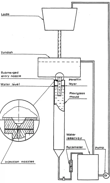
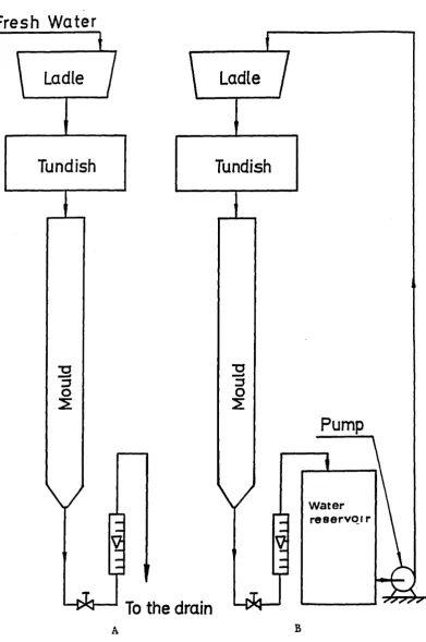
3.1 Development and control of water model system 3:1
3.1.1 Introduction 3:1
3.1.2 Choice of scale 3:1
3.1.3 Model design calculations 3:5
3.1.4 Mould 3:7
3.1.5 Tundish and tundish nozzles 3:8
3.1.6 Ladle 3:12
3.1.7 Water flow modes 3:12
3.1.8 Control of water levels 3:19
3.1.9 Water flow rate measurement 3:19
3.2 Experimental techniques for
fluid flow pattern visualization 3:21
3.2.1 Choice of tracers 3:21
3.2.2 Preparation and addition of the tracers 3:23
3.2.3 Illumination of fluid flow domain 3:24
3.2.4 Recording of the fluid flow patterns 3:27 3.3 Experimental technique for
simulating inclusion separation 3:27
3.3.1 Introduction 3:27
3.3.2 Method of simulation 3:27
3.3.3 Preparation of the coloured paraffin 3:27
3.3.4 Coloured paraffin injection system 3:28
3.3.4.1 Injection assembly 3:28
3.3.4.2 Injection nozzles 3:30
3.4 Analytical techniques 3:30
3.4.1 Analytical equipment 3:30
3.4.2 Sampling technique 3:30
3.4.3 Sample preparation 3:31
3.4.4 Calibration curve 3:31
3.4.5 Absorbance analyses 3:36
3.5 Experimental technique for measuring
inclusion particle sizes 3:36
to 3:40 4 THEORETICAL DEVELOPMENT
4.1 Inclusion mass transfer coefficient at the meniscus surface incorporating the effect of
Stokes rise 4:1
4.1.1 Introduction 4:1
4.1.2 Transport equations and boundary
conditions 4:3
4.1.3 Solution of transport equations 4:4
4.1.4 Average inclusion diffusion flux 4:5
4.1.5 Effective mass transfer coefficient for
inclusion removal 4:7
4.2 Zonal sump flow model used to analyse
inclusion removal 4:13
4.2.1 Description of the flow field 4:13
4.2.2 Description of the mass fluxes in the
sump 4:16
4.2.3 Description of the inclusion fluxes 4:18
4.2.4 Inclusion removal model 4:23
4.2.5 T equation 4:31
to 4:34 5 EXPERIMENTAL RESULTS
5.1 Fluid flow studies 5:1
5.1.1 Introduction 5:1
5.1.2 Effect of SEN geometry 5:1
5.1.3 Effect of SEN submerged depth 5:2
5.1.4 Effect of casting speed 5:4
5.1.5 Entry nozzle stream penetration 5:4
5.2 Inclusion separation studies 5:4
5.2.1 Introduction 5:4
5.2.2 Effect of SEN submerged depth 5:5
5.2.3 Effect of SEN geometry 5:6
5.2.4 Effect of gas bubbling 5:6
5.2.5 Effect of casting speed 5:8
5.2.6 Effect of the size of injection nozzle 5:8
5.3 Inclusion particle size measurement 5:8
to 5:121 DISCUSSION
6 .1 Accuracy and errors of the experimental method 6 :1
6.1.1 Flowrate measurement 6 :3
6.1.2 Calculation of casting speed from the
flowrate measurement 6:4
6.1.3 Colorimetric measurement 6:5
6.1.4 Coloured and colourless paraffin volume
measurement 6 :5
6.1.5 Errors in inclusion removal ratio
determination 6:6
6 .2 Fluid flow patterns developed 6:6
6.2.1 Effect of SEN geometry 6:7
6.2.2 Effect of SEN submerged depth 6:12
6.2.3 Effect of casting speed 6:14
6.3 Interpretation of experimental results 6:14
6.3.1 Determination of the values of a, /?, f
and v 6:16
6.3.2 Analysis of the results for T 6:25
6.3.3 Analysis of the results for D and R 6:26 6.3.4 Sensitivity to changes in the^mixing
parameter values 6:34
6.3.5 Sensitivity to changes in the value of (5 6:35 6.3.6 Sensitivity to changes in the value of
the inclusion mass transfer coefficient 6:38 6.3.7 Effects of the operation practice on the
inclusion removal 6:42
6 .3.7.1 Effect of SEN geometry 6:42
6 .3.7.2 Effect of SEN submerged depth 6:43
6 .3.7.3 Effect of SEN port angle 6:47
6 .3.7.4 Effect of gas bubbling 6:48
6 .3.7.5 Effect of casting speed 6:51
6.4 Estimation of the values of the diffusion mass transfer coefficients from the
experimentally measured inclusion removal
ratios 6:51
6.5 Role of inclusion agglomeration in the sump
flow patterns 6 :55
6.6 Predication of inclusion agglomeration rates
due to turbulent shear and gravity field flow 6:57 6.7 Prediction of ninclusion . , . for steel casting°
system (prototype) 6:70
to 6:79
7 CONCLUSIONS 7:1 to 7:2
8 FURTHER WORK 8:1 to 8 :
9 REFERENCES 9:1 to 9:
APPENDIX 1 Estimation of the values of the mixing
parameters based on jet entrainment theory Al: Al.l Velocity profile in a round submerged jet Al: A1.2 Velocity variation along the axis of a
round submerged jet Al:
A1.3 Momentum conservation Al:
A1.4 Jet entrainment Al:
A1.5 Jet entrainment flux Al:
A1.6 Values of T and r TM.JK JM Al:
to Al:
APPENDIX 2 Programme List A2:1 to A2:
1
9
1
1 4 7 9 11 12 14 7
LIST OF SYMBOLS
a fractional jet projected area ( see Equation (4.35) ); constant
A_ mould cross section area at meniscus
Aj jet projected area onto a horizontal plane b width of the billet mould, mm;
constant (see Equation (A1.12) )
C a concentration of inclusion of diameter a empirical constant (see Equation (4.24) )
material property related constant (see Equation (6.54) ), m-1. s -1
d^ SEN port diameter, mm dp diameter of particle, mm
d z inside diameter of the nozzle, mm D diameter of the orifice, mm
Dg eddy diffusivity, m2 .s-x Dp diameter of particle, mm Dp diameter of particle, m
D^ turbulent diffusivity, n^.s-1 D z outside diameter of the nozzle, mm’ e enhancement factor (see equation 4.59) f, mass fraction of inclusion of diameter D
d P
fj volume fraction of inclusions in the jet stream
f^ volume fraction of inclusion in the recirculation region F total cross section area of jet
Fr Froude Number
gravitational acceleration, m.s*2
fluid hydraulic head above the orifice, m fluid hydraulic head scale factor
flux of inclusions of a diameter a denote the jet entrainment zone turbulence kinetic energy
Kg , <7^, empirical constants Prandtl mixing length, mm
characteristic length;
width of the bloom mould, mm; SEN length, mm
length scale factor length in the model, m length in the prototype, m
mass flow through cross section of jet, Kg.s-1 momentum flow of the fluid at jet pole, Kg.m.s*2
momentum flow through a jet at a distance x from jet pole, Kg.m .s -2
mass flux of inclusions, K g . m ^ . s -1
average mass flux of inclusions, K g . m ^ . s -1 denote the mixing zone
casting mass flow rate, Kg.s*1
interchange mass flux between the jet entrainment zone and the mixing zone, K g . m ^ . s -1
interchange mass flux between the jet entrainment zone and the recirculation zone, K g . m ^ . s *1
N collision rate •
^grad collision rate due to velocity gradient N- collision rate due to stokes rise
Q^. volume flow rate scale factor r distance from the jet axis, mm
r^ distance between the jet axis and the point at which the velocity is equal to the half of the axial velocity, mm r o nozzle radius of a iet, mmJ
R denote the recirculation zone; ratio of inclusion diameters Re Reynolds Number
t time, s
t^ time scale factor u velocity, m.s-1
axial velocity (velocity on the jet axis), m.s-1 uq axial velocity at jet pole, m.s-1
Stokes' rising velocity of particle, m.s-1 velocity gradient, s -1
v^ casting speed, m.min-1 V velocity, m.s-1
V^p velocity scale factor
•
Vj initial volume flow from jet, n^.s-1
volume flow through a given section of jet at a distance x, m 3 . s - x
V entrain jet entrainment volume flow, m 3J ’
V. . injected, volume of coloured paraffin injected, mlr J ’
^in slag volume of coloured paraffin absorbed into the slag
layer, ml
normal component to the surface of eddy velocity, m.s*1 volumetric flowrate of fluid of the jet stream, n^.s-1 volumetric flowrate of fluid within the recirculation region, m 3^ - 1
inclusion relative rising velocity, m.s-1 eddy velocity of size A0, m.s-1
Weber Number
weight of particles injected, Kg
weight of particles remained in tundish, Kg
distance between a given section and jet pole, mm distance from the surface, mm
distance between two particles normal to the flow direction dimensionless effective inclusion mass transfer coefficient effective mass transfer coefficient for the removal of
inclusions of diameter D , m.s-1 P
ratio of liquid flux as defined in Equation (4.57) integration variable;
limit of relative error
rate of dissipation of turbulence kinetic energy; limit of absolute error
stirring power per unit volume size of the eddies, mm
molecular viscosity, N.s.m-2 effective viscosity, N.s.m-2
v kinematic viscosity, n^.s-1
p density, Kg.m*3
Pe resistivity of the fluid Pp density of particle, Kg.m-3 pg density of liquid steel, Kg.m-3 7 as defined in Equation (6.27), mm -2
6 SEN port angle
a surface tension, dyne.cm-1
r time, s
r total exposure time of fluid packet at the meniscus, s r* dimensionless exposure time of fluid packet at the meniscus f dimensionless distance from the jet axis (see Equation
(Al.7) ); A absolute error
Afg increment of the volume fraction of inclusions in the recirculation zone
AR change of electrical resistance of the fluid Au velocity difference between two particles
(collision height), m.s-1
S relative error
v dimensionless Stokes rise velocity (see Equation (4.34) ) f obscuration factor of the upper surface of the meniscus T dimensionless liquid flux
Txx dimensionless liquid interchange flux between zones particle collision volume per unit time, n^.s-1 $ variable as defined in Equation (4.47)
T . . entrain dimensionless jet entrainment mass fluxJ
r en dimensionless jet entrainment mass fluxJ
n .inclusion 7 . inclusion separation ratio in percentile termsr r
|3u/3y| absolute value of the velocity gradient along a direction perpendicular to the direction of flow
subscript
d denote that for inclusion of diameter d
m model;
mixing zone
p prototype (steel casting system) R recirculation zone
JM denote that between jet entrainment and mixing zones
JR denote that between jet entrainment and recirculation zones
LIST OF TABLES Table TABLE TABLE TABLE TABLE TABLE TABLE TABLE TABLE TABLE TABLE TABLE TABLE TABLE TABLE
No. Titles
3.1 Physical properties of water at 20°C and steel at 1600°C
3.2 Billet tundish nozzle dimensions 3.3 Bloom tundish nozzle dimensions
3.4 Effect of heating process on the colour changes of the samples
3.5 Calibration Data
5.1 Effect of SEN submerged depth on nozzle stream penetration
5.2 Effect of SEN submerged depth on inclusion removal (Nozzle 1)
5.3 Effect of SEN submerged depth on inclusion removal (Nozzle 2)
5.4 Effect of SEN submerged depth on inclusion removal (Nozzle 3)
5.5 Effect of SEN submerged depth on inclusion removal (Nozzle 4)
5.6 Effect of SEN submerged depth on inclusion removal (Nozzle 5)
5.7 Effect of SEN submerged depth on inclusion removal (Nozzle 6)
5.8 Effect of SEN submerged depth on inclusion removal (Nozzle 7)
5.9 Effect of SEN submerged depth on inclusion removal (Nozzle 8)
TABLE TABLE TABLE TABLE TABLE TABLE TABLE TABLE TABLE TABLE TABLE TABLE TABLE TABLE TABLE TABLE
.10 Effect of SEN submerged depth on inclusion removal (Nozzle 9)
.11 Effect of SEN submerged depth on inclusion removal (Nozzle 10)
.12 Effect of SEN submerged depth on inclusion removal (Nozzle 11)
.13 Effect of gas bubbling on inclusion removal (Nozzle 1)
.14 Effect of gas bubbling on inclusion removal (Nozzle 4)
.15 Effect of gas bubbling on inclusion removal (Nozzle 5)
.16 Effect of gas bubbling on inclusion removal (Nozzle 10)
.17 Effect of casting speed on inclusion removal .18 Effect of SEN submerged depth on inclusion
removal for large injection nozzle
.19 Effect of SEN submerged depth on inclusion removal for small injection nozzle
.20 Diameters of the particles generated from the large injection nozzle
.21 Diameters of the particles generated from the small injection nozzle
.1 Values of f for the bloom mould model .2 Values of f for the billet mould model .3 Example of screen output
.4 The values of R
TABLE 6 .
TABLE 6 .
TABLE 6 .
TABLE 6 .
The values of a* estimated from the experimentally
measured inclusion removal ratios 6:53
The value of estimated from the experimentally
measured inclusion removal ratio 6:56
Predictions on the inclusion removal ratios n . ,inclusion for bloom steel casting system (prototype) 6:74 Predictions on the inclusion removal ratios n.inclusion , for billet steel casting system (prototype) 6:76
LIST OF FIGURES Figure Figure Figure Figure Figure Figure Figure Figure Figure Figure Figure Figure Figure Figure Figure
No. Captions
2.1 Schematic representation of the fluid flow field 2.2 Sketches over the fluid flow pattern developed in
a CC-mould using different submerged entry nozzles 2.3 Water model experiment on fluid flow pattern
influenced by the exit angle of nozzle 2.4 Profile of submerged entry nozzles 2.5 Fluid flow patterns of resin particles
in water pool
2.6 Relation between extracted large inclusion (>50 /zm) content in accumulated zone of slabs and
penetration depth of casting stream in sump
2.7 Mould fluid flow pattern with a straight-discharge SEN (no gas bubbling)
2.8 Mould fluid flow pattern with a straight-discharge SEN (with gas bubbling)
2.9 Mould fluid flow pattern with a 4-ported SEN (with gas bubbling)
2.10 Percent separation of glass microspheres as a function of dimensionless time
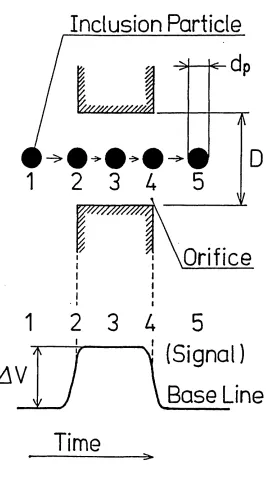
2.11 Principle of particle detection by the E.S.Z. method
2.12 Schematic of the E.S.Z. system
2.13 Photograph of E.S.Z. probe developed
2.14 Comparison of weight-based separation ratios using the weighing method and the E.S.Z. method
Figure 2.15 Comparison of weight-based separation ratios
using the weighing method and the E.S.Z. method 2:38 Figure 3.1 Experimental set up for recirculation mode 3:2 Figure 3.2 Sketches of the billet mould assembly 3:9 Figure 3.3 Sketches of the bloom mould assembly 3:10
Figure 3.4 Sketches of the tundish assembly 3:11
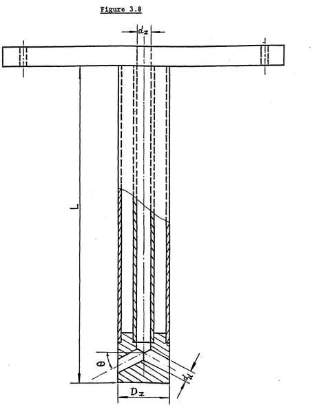
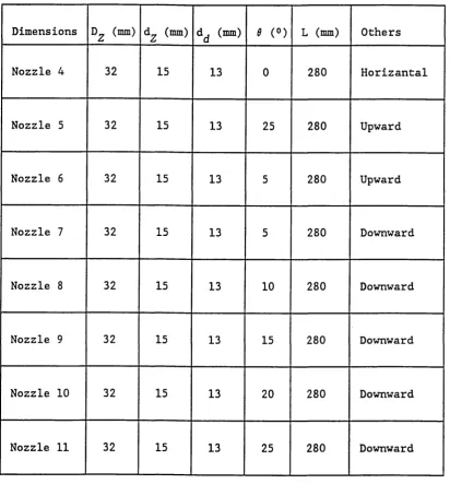
Figure 3.5 Design of submerged entry nozzle' 3:13
Figure 3.6 Design of submerged entry nozzle with
horizontal outlets 3:14
Figure 3.7 Design of submerged entry nozzle with
upward outlets 3:15
Figure 3.8 Design of submerged entry nozzle with
downward outlets 3:16
Figure 3.9 Sketches of the water flow modes employed 3:18 Figure 3.10 Experimental set-up for the rotameter calibration 3:20
Figure 3.11 Rotameter calibration curve 3:22
Figure 3.12 Injection nozzle set-up 3:25
Figure 3.13 Sketches of the slide slit used in the projector 3:25 Figure 3.14 Sketches of the plane light source arrangement 3:26 Figure 3.15 Sketches of the coloured paraffin injection System 3:29 Figure 3.16 Sketches of the sample suction system 3:32
Figure 3.17 Calibration curve 3:34
Figure 3.18 Sketch of the tube for viewing
the particle generation 3:38
Figure 3.19 Experimental arrangement for close-up viewing 3:39 Figure 3.20 Experimental arrangement for general viewing 3:40
Figure 4.1 Stokes velocity and‘mass transfer coefficients as a function of inclusion size
Figure 4.2 Schematic diagram of mixing regions in the sump of a continuous casting machine showing the interchange fluxes (Bloom)
Figure 4.3 Schematic diagram of mixing regions in the sump of a continuous casting machine showing the interchange fluxes (Billet)
Figure 4.4 Schematic representation of mixing zones in sump of a continuous casting machine
Figure 4.5 Schematic diagram of inclusion interchange fluxes between zones
Figure 4.6 Schematic diagram of inclusion interchange fluxes in conductance net-work form
Figure 5.1 The position of the view planes
Figure 5.2 Effect of SEN submerged depth on length of jet penetration zone
Figure 5.3 Effect of SEN submerged depth on the proportion of inclusion removed to the 'slag1 layer (Nozzle 1) Figure 5.4 Effect of SEN submerged depth on the proportion of
inclusion removed to the 'slag' layer (Nozzle 2) Figure 5.5 Effect of SEN submerged depth on the proportion of
inclusion removed to the 'slag' layer (Nozzle 3) Figure 5.6 Effect of SEN submerged depth on the proportion of
inclusion removed to the 'slag' layer (Nozzle 4) Figure 5.7 Effect of SEN submerged depth on the proportion of
inclusion removed to the 'slag' layer (Nozzle 5)
:11
: 14
:15
: 17
:19
4:24 5:27
5:28
5:29
5:30
5:31
5:32
5:33
Figure
Figure
Figure
Figure
Figure
Figure
Figure
Figure
Figure
Figure
Figure
Figure
Figure
.8 Effect of SEN submerged depth on the proportion of inclusion removed to the 'slag' layer (Nozzle 6)
.9 Effect of SEN submerged depth on the proportion of inclusion removed to the 'slag' layer (Nozzle 7) .10 Effect of SEN submerged depth on the proportion of
inclusion removed to the 'slag' layer (Nozzle 8) .11 Effect of SEN submerged depth on the proportion of
inclusion removed to the 'slag' layer (Nozzle 9) .12 Effect of SEN submerged depth on the proportion of
inclusion removed to the 'slag' layer (Nozzle 10) .13 Effect of SEN submerged depth on the proportion of
inclusion removed to the 'slag' layer (Nozzle 11) .14 Effect of SEN geometry on the proportion of
inclusion removed to the 'slag' layer (billet) .15 Effect of SEN port angle on the inclusion removal
efficiency for different submerged depth .16 Effect of gas bubbling on the proportion of
inclusion removed in the billet caster .17 Effect of gas bubbling on the proportion of
inclusion removed in the bloom caster (Nozzle 4) .18 Effect of gas bubbling on the proportion of
inclusion removed in the bloom caster (Nozzle 5) .19 Effect of gas bubbling on the proportion of
inclusion removed in the bloom caster (Nozzle 10) .20 Effect of casting speed on the proportion of
inclusion removed to the 'slag' layer
5:34
5:35
5:36
5:37
5:38
5:39
5:40
5:41
5:42
5:43
5:44
5:45
5:46
Figure 5.21 Effect of injection nozzle size on the inclusion removal ratio in the bloom mould model
Figure 6.1 Sketch of the fluid flow pattern developed in the billet mould sump
Figure 6.2 Sketch of the fluid flow pattern developed in the bloom mould sump
Figure 6.3 Jet projected area in the bloom mould Figure 6.4 Jet projected area in the billet mould Figure 6.5 Determination of and R for an SEN
submerged depth of 220 mm
Figure 6.6 The values of R and SEN submerged depth
Figure 6.7 The particle diameter and SEN submerged depth Figure 6.8 Inclusion removal efficiency in the
bloom mould model ( effect of T ) Figure 6.9 Inclusion removal efficiency in the
bloom mould model ( effect of fi ) Figure 6.10 Inclusion removal efficiency in the
bloom mould model ( effect of a* )
Figure 6.11 Relationship between stirring force and the number of inclusions for each stirring direction
Figure 6.12 Schematic view of M-EMS stirring directions Figure 6.13 Schematic view of the flow pattern developed
in the mould with gas bubbling
Figure 6.14 Generic slice of the unitary collision volume Figure 6.15 Diagram of particles rising under Stokes Law Figure 6.16 Diagram of particles moving with fluid in
a velocity gradient field
5:119
6:8
6:9 6:17 6:19
6:28 6:32 6:33
6:36
6:39
6:41
6:45 6:46
6:50 6:58 6:61
6:62
Figure
Figure
Figure Figure
Figure
Figure
Figure
Figure
Figure Figure
6.17 Collision volume involved in
the gradient collision 6:64
6.18 Illustration of the approach of a larger particle
to a smaller one 6:68
6.19 Collision efficiency E as a function of a 6:69 6.20 Grazing particle trajectories for
values of ff = 0.2, 0.7, 5.0 6:69
6.21 Inclusion removal efficiency in the
bloom caster (effect of Vc) 6:75
6.22 Inclusion removal efficiency in the
billet caster (effect of Vc) 6:77
6.23 Inclusion removal efficiency in the
bloom caster (effect of f) 6:78
6.24 Inclusion removal efficiency in the
billet caster (effect of f) 6:79
Al.l Diagram of a submerged free jet Al:2
Al.2 Dimensionless velocity profile in the main
region of axially symmetric submerged jet Al:3
LIST OF PLATES
Plate No. Captions
Plate 5.1 Fluid flow patterns developed on plane 1 when different SEN were used
Plate 5.2 Fluid flow patterns developed on plane 2 when different SEN were used
Plate 5.3 Fluid flow patterns developed on plane 3 when different SEN were used
Plate 5.4 Fluid flow patterns developed on plane 1 when different SEN were used
Plate 5.5 Fluid flow patterns developed on plane 2 when different SEN were used
Plate 5 .6 Fluid flow patterns developed on plane 3 when different SEN were used
Plate 5.7 Fluid flow patterns developed on central plane when different bifurcated SEN were used
Plate 5.8 Fluid flow patterns developed on central plane when different bifurcated SEN were used
Plate 5.9 Fluid flow patterns developed on central plane when different bifurcated SEN were used
Plate 5.10 Fluid flow patterns developed on central plane when different bifurcated SEN were used
Plate 5.11 Fluid flow patterns developed on central plane when different bifurcated SEN were used
Plate 5.12 Fluid flow patterns developed on plane 1 using Nozzle 1 at different submerged depths
Page
5:51
5:53
5:55
5:57
5:59
5:61
5:63
5:65
5:67
5:69
5:71
5:73
Plate 5.13 Fluid flow patterns developed on plane 2
using Nozzle 1 at different submerged depths 5:75 Plate 5.14 Fluid flow patterns developed on plane 3
using Nozzle 1 at different submerged depths 5:77 Plate 5.15 Fluid flow patterns developed on plane 1
using Nozzle 1 at different submerged depths 5:79 Plate 5.16 Fluid flow patterns developed on plane 2
using Nozzle 1 at different submerged depths 5:81 Plate 5.17 Fluid flow patterns developed on plane 3
using Nozzle 1 at different submerged depths 5:83 Plate 5.18 Fluid flow patterns developed on plane 1
using Nozzle 2 at different submerged depths 5:85 Plate 5.19 Fluid flow patterns developed on plane 2
using Nozzle 2 at different submerged depths 5:87 Plate 5.20 Fluid flow patterns developed on plane 3
us ing Nozzle 2 at different submerged depths 5:89 Plate 5.21 Fluid flow patterns developed on plane 1
using Nozzle 2 at different submerged depths 5:91 Plate 5.22 Fluid flow patterns developed on plane 2
using Nozzle 2 at different submerged depths 5:93 Plate 5.23 Fluid flow patterns developed on plane 3
using Nozzle 2 at different submerged depths 5:95 Plate 5.24 Fluid flow patterns developed on plane 1
using Nozzle 3 at different submerged depths 5:97 Plate 5.25 Fluid flow patterns developed on plane 2
using Nozzle 3 at different submerged depths 5:99 Plate 5.26 Fluid flow patterns developed on plane 3
using Nozzle 3 at different submerged depths 5:101
Plate 5.27 Fluid flow patterns developed on plane 1 using Nozzle 3 at different submerged depths Plate 5.28 Fluid flow patterns developed on plane 2
using Nozzle 3 at different submerged depths Plate 5.29 Fluid flow patterns developed on plane 3
using Nozzle 3 at different submerged depths Plate 5.30 Fluid flow patterns developed on central plane
using Nozzle 4 at different submerged depths Plate 5.31 Fluid flow patterns developed on central plane
using Nozzle 5 at different submerged depths Plate 5.32 Fluid flow patterns developed on central plane
using Nozzle 9 at different submerged depths Plate 5.33 Fluid flow patterns developed on central plane
using Nozzle 11 at different submerged depths Plate 5.34 Fluid flow patterns developed on plane 1
using Nozzle 3 at different casting speeds Plate 5.35 Close-up view of the tip area when particles
being generated
Plate 5.36 General view of the tip area when particles being generated
Plate 6.1 Fluid flow pattern observed in the bloom mould model
Plate 6.2 View of the meniscus when small SEN submerged depth was being used
5:103
5:105
5:107
5:109
5:111
5:113
5:115
5:117
5.120
5.121
6.10
6:13
Chapter 1
1. INTRODUCTION.
1.1. Foreword.
Continuous casting is, today, a process used extensively throughout the metallurgical industry and, because the number of plants
installed with continuous casting machines is increasing steadily, problems associated with the operation and design of the machines are receiving greater attention.
Although many mathematical models have dealt fairly successfully with predicting solidification profiles and fluid flow patterns of liquid steel during continuous casting, the behaviour of inclusions and the quantitative description of their removal in the sump has been
neglected.
Water models have also been extensively employed in recent years to obtain flow descriptions by means of visualization techniques but, although they can also be utilized to study the behaviour of
inclusions in the sump of continuous casting machines, no such work has been previously reported in the literature.
1.2. The objective of the investigation.
The basic objective of the present work is to improve understanding of the factors affecting the internal quality of continuously cast billets, blooms and slabs — particularly on the mechanisms of
inclusion removal in the molten sump — by studying the fluid flow and recirculation patterns in the sump and the behaviour of
inclusions in those flows. Since the behaviour of these inclusions has a crucial bearing on the cleanness of the steel produced the
Chapter 1
principal aim of the present research is to examine this behaviour. Of particular interest will be the feature of the flow patterns that can be controlled and are shown to influence the proportion of
inclusions that can be incorporated into the molten flux layer maintained on the liquid metal meniscus.
These consist
of:-a) Studying the fluid flow and recirculation in the sump of a continuous casting machine in a room temperature three dimensional model.
b) Developing a method for studying the apportionment of input inclusions between the molten mould powder layer and the solidification zone by using finely dispersed dye-marked organic liquid phase in the inlet stream and a floating organic layer to simulate the molten powder layer on top of the molten steel meniscus;
c) Studying the effect of fluid flow in the sump on inclusion removal in the room temperature model using the method developed;
d) Varying the operating and design parameters such as nozzle size, position and geometry and casting speed to elucidate their effect on inclusion removal mechanisms;
Chapter 2
2. LITERATURE SURVEY.
2.1. General overview.
In order to understand the influences of fluid flow in the sump on inclusion removal during continuous casting, it is important to appreciate the key developments of previous workers.
The purpose of the present literature survey is not to be a thorough review of the literature, but rather to enable the experimental results and conclusions to be considered in their right perspective, and to serve as a basis on which the new ideas and theories will be developed.
2.1.1. Development of continuous casting.
In the past three decades, continuous casting has emerged as a [1-41
widely used technology in modern steel plants . This is because the continuous casting process has offered numerous technical and economical advantages. They are,
mainly:-a) 10% and more higher yield compared to traditional ingot methods.
b) More uniform and higher quality of the final product.
c) Reduced energy consumption together with the potential for even less energy consumption through hot charging of
continuously cast products to the rolling mill furnace. d) Reduced operating costs.
e) Less capital and depreciation costs. f) Good environmental conditions.
Chapter 2
g) Improved working and safety conditions for the operators. h) Process suited for integral automation.
i) High productivity.
j) Less space and time required to convert liquid steel into solidified product.
Because of the improved yield and the operating cost benefits, the continuous casting process will dominate the production schedule of most steelmaking plants in the near future, especially in view of the
technological developments under way. Indeed, the continuous casting ratio is likely to increase to more than 90% by the end of this
century.
2.1.2. Quality requirements for the continuously cast products.
Continuous casting of steel has become a widely used process and an important development in the manufacture of steel. The ratio of continuously cast steel on the total steel production had been increased dramatically in the last two decades Concurrent with this increase in production levels are the stringent quality
requirements. These quality aspects — mainly surface finish and internal cleanness — have become crucial with progressively increasing machine throughputs and larger product dimensions. Therefore, steel cleanness and strict composition control are now becoming the primary concern of steelmakers. After investigation, several authors ^ have found that metal flow in the mould is an important parameter bearing upon the quality of continuously cast products.
2.2. Fluid flow patterns.
Chapter 2
It is well known that the fluid flow of liquid steel plays an
important role in the whole process of continuous casting. In fact, the beginning of the continuous casting process is primarily
concerned with liquid metal flow in the tundish and the mould. Thus the concepts of fluid flow and hydrodynamics have been used to solve major problems and to improve the efficiency of the process. Research work leading to better understanding of liquid metal flow has been carried out extensively, mainly in two ways, an empirical approach and a theoretical approach.
2.2.1. Empirical approach.
The fluid flow problems involved in the continuous casting process are often too complicated to be treated using fundamental equations without the introduction of approximations and boundary conditions in the calculations. Fortunately, there are several experimental methods available nowadays which could be employed to study the flow patterns developed.
2.2.1.1. Experimental methods.
The experimental methods used to study fluid flow patterns in the continuous casting process may be classified into two groups, namely water modelling studies on different scale physical model systems and radioactive tracer studies on full scale operating plant.
The stimulus-response method and the elapse-time photograghic
technique are the most commonly used methods for studying fluid flow within the continuous casing system via the water models. The
Chapter 2
stimulus-response method can be explained as: "Do something to a system and then see how the system responds". By using this method, the residence-time distribution can be obtained^^ , and hence desired information about the fluid flow in the continuous casting system will be revealed.
When taking pictures of the fluid flow pattern in water models, the following techniques are available for fluid flow visualization:
a) Particle-addition into the water systems. b) Dye-injection into the streams.
c) Use of a slit light sources to illuminate the fluid flow domain two-dimensionally.
Plastic particles, glass beads, vanadium pentoxide, the tea leaves, computer card punchings, sawdust and even gas bubbles are some of the additions made so that flow can be seen and photographically
recorded. Dye injected into the model can be used to demonstrate the configuration of the inlet stream and its penetration depth. The use of the slit light source allows visualization of the fluid flow
pattern on a definite plane without the interference caused by other parts of the fluid flow domain.
For the quantitative description of the fluid flow pattern, the T 28 - 311
following methods can be used to measure the flow velocity at certain points in the domain:
a) Impact tube and static pressure tap with manometer. b) Form drag strain gauge system with strain amplifier and
recorder.
Chapter 2
c) Laser doppler anemometer. d) Thermistor probe.
e) Hot film anemometry. f) Stroboscopic photography.
2.2.1.2. Water modelling.
The literature describing water model studies is very [3-28]
extensive.
The fluid flow of liquid steel in the actual continuous casting system is very difficult to measure or observe. Even in the open pouring situation, the observation can only be made on the open pouring streams. In this sense, a water model is very useful and highly instructive. But the results obtained on the physical model are meaningful and useful only if physical similarity between
physical model and actual system is achieved.
To obtain similarity between two flowing systems, the following four r
31
-33]conditions must be satisfied.L
a) Geometric Similarity:
the ratio of any length in one system to the corresponding length in the other system is constant. This ratio is termed as the scale factor.
b) Kinematic Similarity:
the streamlines in one system are geometrically similar to the streamlines in the other system.
c) Dynamic Similarity:
Chapter 2
the magnitude of forces at corresponding location in each system are in a fixed ratio.
d) Thermal Similarity:
the dimensionless numbers involving heat transfer or convective flow are equal in both systems.
Thermal similarity is not important in modelling the upper region in the mould of the continuous casting system since thermal gradients are small and convective forces are negligible. This is fortunate, as it is difficult to achieve both thermal and fluid flow similitude in
^ ^ i t32]
the same model.
Kinematic similarity is observed in the model that attains dynamic and geometric similarity. The principal forces to be considered in obtaining dynamic similarity in the continuous casing mould are inertial, gravitational, viscous and surface tension forces. The various ratios of these forces form certain dimensionless
numbers. Dynamic similarity exists if these numbers have the same value in both the model and the actual system.
Three important dimensionless numbers in fluid flow
are:-V 2 inertial force Froude No Fr = ----
=---gL gravity force
VL inertial force Reynolds No Re = ----
=---v viscous force
Chapter 2
pV2L inertial force
Weber No We — --- = ---o surface tension force
where: V: stream velocity;
g: gravitational constant; L: characteristic length; u: kinematic viscosity; a: surface tension; p : density.
Because of difference of the physical properties of water at room temperature and molten steel, table 3.1, it is impossible to satisfy simultaneously all the three dimensionless numbers mentioned above in the same model of a given particular scale. It requires a full scale water model to satisfy Reynolds and Froude numbers
concurrently. But a model of 0.6 scale is needed to satisfy the Froude and Weber numbers concurrently. It had been demonstrated by
[34]
Heaslip et al. that the Froude number alone could be satisfied at any scale in a mould water model as long as all metering orifices and fluid hydraulic heads in the modelling system are varied in
accordance with a single scaling factor. To decide what scale of model should be used, the extent to which similitude is necessary in modelling the actual system must be considered.
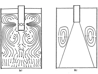
A full scale model has been used by Szekely and Yadoya^^^ to examine velocity profiles in round continuous casting moulds using submerged vertical outlet and horizontal outlet nozzles. The flow fields obtained are shown in figure 2.1. It was also found that, for the vertical outlet nozzles, the flow patterns did not depend markedly on
unapter z
Figure 2.1
(b) )(>
f 281
Schematic representation of the fluid flow field. (a) — radial flow nozzle;
(5) — straight nozzle.
Chapter 2 ^ \ the flow rates through the system, except that, at higher flow rateL,— -the jet penetrated more deeply into -the column. The jet penetration depth was found to be about 4 to 6 mould diameters. For the
horizontal outlet nozzles, the jet penetration depth varied between half and one mould diameters.
[141
Using a full scale model, Wei and Carlsson studied the flow patterns developed in a bloom mould when different submerged entry nozzles ( SEN ) are used. The results are given in figure 2.2. They found that vertical outlet nozzles gave a high degree of by-passing and horizontal outlets nozzles gave some plug flow inside the mould.
Later on a full scale water model of continuous casting system was [31
built by Hibbins et al. to investigate mould fluid flow conditions with different submerged nozzles. The results were of great
assistance in operating the bloom caster at the author's steelworks.
[41
Of the recent work, the paper by Tai et al. is perhaps the most noteworthy as these investigators have shown that rotating fluid flow can be developed in bloom continuous casting mould when a four-ports nozzle is installed unsymmetrically relative to the rectangular
mould. Industrial experiments have shown that the rotating metal flow developed in the mould by turning the nozzle axis 15 degrees is
beneficial in improving the internal cleanness of low carbon steel and reducing the erosion rate of nozzle refractories.
The 0.6-scale models, in which Froude-Weber criteria are satisfied, have proven popular in the study of fluid flow in continuous casting
Figure 2.2
A
Open stream
Vertical outlet
Two holed outlet
Four holed outlet
Sketches over the fluid flow pattern developed in a CC-mould using different submerged entry nozzles. [14]
Chapter 2
employed. Astrov et a l . ^ used a three-fifth scale water model to study the effects of the port sloping angle of the submerged multi ports nozzles on the fluid flow in the mould. After careful study using a 2/3-scale model, Robertson and S h e r i d a n s u g g e s t e d a
suitable multi-stream arrangement for continuously casting 36 x 5.5in slabs to eliminate the longitudinal split formed in the centre of the broad face. Mould flow patterns produced by bifurcated nozzles have been studied by Mills and Barnhardt^^ . As result of their
investigations, the need for skin scarfing (i.e., to improve surface quality) was eliminated from a production plant. M c P h e r s o n h a s similarly reported the water modelling results about a continuous slab caster with the aid of an 0 .6-scale model.
Other scale models, in which only the Froude criterion is satisfied, are appropriate for studying the flow patterns and their relation to phenomena such as vortex formation and fluid residence time and its distribution. A 1/2.5-scale model was used by Nemo to and Kawawa^*^ to observe the stream patterns in the mould. Figure 2.3 shows one of their results. They found that, when the exit angle 6 is too small, the meniscus is exposed to oxidation by the air and when the angle is too big, the steel temperature in the meniscus is lower than required. Their investigation suggested the optimum value of 6 for different dimensions of the mould. After the investigations using a 1/4-scale
T 381
model, Habu et al. have suggested that the use of a diverging bottle shaped submerged entry nozzle, shown in figure 2.4, reduces the jet penetration depth, and, therefore, the number of large inclusions accumulated in the strand, as shown in figure 2.5 and figure 2 .6 .
Figure 2.3
Water model experiment on fluid flow pattern influenced by the exit angle of nozzle
Simulation factor:
V 2
Fr
L g
V: stream speed; L: length;
g: gravitational acceleration.
Figure 2.4
Bottle nozzle
50 mm
S
25
n
'H i
Ordinary nozzli
Profile of submerged entry nozzles [38]
Figure 2.5
U
Ordinary nozzle B o ttle nozzle
Fluid flow patterns of resin particles in water pool. [38]
U U d p b B t 4
.
Figure 2.6
s 200
-4-1c/l tc
g 150
e C/l
C
o
S loo
oc
50
° From cast structure
x From solute distribution
O H h
2
3
4
5
6
P e n e tra tio n depth (m)
Relation between extracted large inclusion (>50 /im) content in accumulated zone of slabs and penetration depth
* • • .[38]
of casting stream m sump
Chapter 2
2.2.1.3. Radioactive tracer studies.
In contrast to the large number of reported investigations concerned with water modelling studies, the literature available on the
radioactive tracer studies in operating continuous casting mould is
[39-41]
f39]
rather scanty. The work done by Krainer et al. 1 and
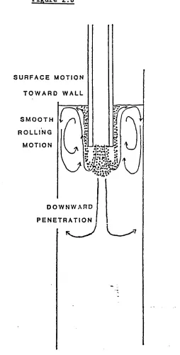
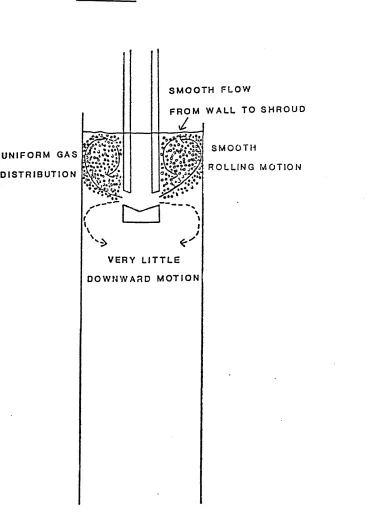
Arnoult et al. respectively in the past gave the picture of the flow patterns in the sump. As a result of their investigations, it was generally agreed that for the straight nozzles the liquid pool may be divided into three regions — the upper region where there exists turbulent recirculation driven by the incoming metal stream, an intermediate zone where the liquid flow is driven by natural
convection, and finally a lower part where fluid motion is negligible because of the confined nature of the spaces available for flow. It was also found that the stream penetrates to a length of about 4 to 6 mould widths. The radioactive tracer method is very useful at
obtaining information on the depth and shape of the sump. But this method could not be used to investigate the fluid flow phenomena more quantitatively, it has not been used quite often nowadays.
2.2.2. Theoretical approach.
At the present time, the problems relating to fluid flow behaviour in continuous casting process cannot be solved theoretically. This is not only because the continuous casting process itself is very complicated, but also because the fundamental equations which describe fluid flow are often too complex to be solved even using large computers. For instance, the Navier-Stokes equation and the
[43] continuity equation together fully describe fluid flow behaviour,1 J
Chapter 2
but they are extremely complex and their solution, even with the aid of large computers, requires simplifications and assumptions to be made about a number of aspects, e.g. choice of a turbulence
approximation, treatment of boundaries and numerical methods of solution. The simplifications and assumptions chosen, together with the fundamental equations, make up a mathematical model. It is obvious that such mathematical models need to be validated against experimental measurements.
2.2.2.1. Mathematical model.
Mathematical models are primarily confined to heat transfer and solidification phenomena where the fluid flow is usually treated rather simply. Such models were presented by a number of authors,
f441 [451
among them are Savage and Pritchard, J Adenis et al., J Hills, Donaldson and H e s s , ^ ^ Mizikar, F a h i d y ^ ^ and Szekely and Stanek. Later, as the development of the turbulence t h e o r y a n d the improvement of numerical methods for solving multidimensional turbulent flow problems have progressed,
mathematical models of fluid flow in steelmaking processes have been developed by several investigators. t-^-61] Recently, several
mathematical models have been developed to analyse fluid flow in continuous casting tundishes. Up to now, however, little
work has been published on mathematical models of fluid flow in continuous casting moulds. The following section, therefore, reviews work dealing with the mathematical models of fluid flow in continuous casting tundishes.
r 631
The mathematical model developed by Debroy and Sychterz is a
Chapter 2
dimensional one, which describes isothermal, incompressible, steady state and turbulent fluid flow in tundishes. The fundamental
equations used for flow predictions are the equation of continuity and the Navier-Stokes equation in two dimensions. For the computation of the turbulent viscosity, the prandtl's mixing length
r 681 hypothesis is used, which can be written as
:-- Pi2 du
By
where: p: density of the medium; p^\ turbulent viscosity; I: prandtl mixing length;
|3u/3y|: absolute value of the velocity gradient along a direction perpendicular to the direction of flow.
The mixing length is defined
as:-1 = 0.4y.
where: y: distance to the nearest wall. The effective viscosity is expressed
as:-“off
" " t +
where: Peff' effective viscosity;
p: molecular viscosity of the medium.
f 621
Tanaka et al. introduced a three-dimensional mathematical model
Chapter 2
of tundish systems. The equation of continuity and the Navier-Stokes equation in three dimensions were used as the fundamental equations. They employed the k-e model of Jones and Launder to calculate the turbulent viscosity. According to Jones and Launder, the turbulent viscosity is determined
as:-H t - K 1pk*/e
The governing equations for k and e are
respectively:-3 /j __ 3/c
(puLk - ) = G - pe dx. 1 a. dx.k i
and
3 /i ff de
(pu e - ) = (K2G - K3pe) e/k dx. l a e dx.l
du . du . du . where: G = p — + — -)
dx. dx. d x .
i i J
k: turbulence kinetic energy;
e: rate of dissipation of turbulence kinetic energy; A*eff: effective viscosity;
turbulent viscosity;
K x, K2 , K3 , a empirical constants.
They solved the above equations together with boundary conditions. The results were found to be in a good agreement with the
Chapter 2
experimental results they obtained from the physical models.
Similar mathematical models were developed by He and Sahai, Szekely and El-Kaddah^^ and Ilegbusi and Szekely.
Szekely et al. used mathematical models to study fluid flow in the tundishes when flow control devices, such as dams and wires, were employed. The PHOENICS computational package was used for the solution of the equations. And the removal of inclusions in different tundish designs was also assessed.
2.2.2.2. Methods of solving mathematical models
The solution procedures of the mathematical models of fluid flow in continuous casting system are mainly through the solution of the finite difference equations which are derived from the governing differential equations. Thus the methods involve the derivation of finite difference formulations from the differential equations and boundary conditions as well as methods for solving the resulting set of simultaneous non-linear algebraic equations.
The following methods have been used to derive finite difference formulations from the differential equations and the boundary conditions: - ^
a) from Taylor-series expansions;
b) through the integration over a finite volume.
There are many kinds of schemes which may be used in deriving finite difference equations. They are,
mainly:-a) central difference scheme;