GE-INTERNATIONAL JOURNAL OF ENGINEERING RESEARCH
VOLUME -3, ISSUE -5 (May 2015) IF-4.007 ISSN: (2321-1717)
A Monthly Double-Blind Peer Reviewed Refereed Open Access International e-Journal - Included in the International Serial Directories. GE- International Journal of Engineering Research (GE-IJER)
Website: www.aarf.asia. Email: [email protected] , [email protected]
Page 139
DESIGN AND IMPLEMENTATION OF MICROCONTROLLER BASED
SPEED DATA LOGGER
Kriti Jain*, Prem Chand# , Saad Shamsi# , Dimple Taneja#, Rahul Yadav# , Sanjeev Yadav#
*Assistant Professor, ECE Department, Amity University Haryana
#
Student, ASET, Amity University Haryana, India
ABSTRACT
In this project, a data logger for specific application has been designed. This paper
discusses a vehicle speed measurement and display/recording system using IR sensor as
speed sensor. The system mainly consists of two parts namely Tachometer based on IR
Sensor and recording display system using Arduino microcontroller. A battery operated RTC
chip keeps the track of real time clock information and speed is displayed on LCD and
written on the SD Card which is interfaced to the microcontroller. Later, SD card can be
extracted and excel sheet can be generated of the recorded data.
KEYWORDS – ATmega328, Audino, Data Logger, SD Card, Speed.
INTRODUCTION
A data logger is an attractive alternative to either a recorder or data acquisition system
in many applications. Data logging is the measuring and recording of physical or electrical
parameters over a period of time. The data can be temperature, strain, displacement, flow,
pressure, voltage, current, resistance, power, and many other parameters. Its only task is to
acquire data and save the data into its memory. It can be connected to a computer at any time
to allow its collected data to be transferred, processed and analyzed whenever required.
Speed is the indispensable traffic safety issue, probably due to cleared perceived
relationship between vehicle speed, human capabilities and their limitations. The cases of
rash driving and accidents due to over speeding are increasing day by day and require serious
concern. After any incident, the police doesn’t have exact proof of the speed of the vehicle at
GE-INTERNATIONAL JOURNAL OF ENGINEERING RESEARCH
VOLUME -3, ISSUE -5 (May 2015) IF-4.007 ISSN: (2321-1717)
A Monthly Double-Blind Peer Reviewed Refereed Open Access International e-Journal - Included in the International Serial Directories. GE- International Journal of Engineering Research (GE-IJER)
Website: www.aarf.asia. Email: [email protected] , [email protected]
Page 140 So, it becomes necessary keep a track of speed ofvehicles. One solution for this is to
design a microcontroller based system which will do this task automatically without any
human involvement or interference. The main applications of this system will be: It can be
used as a method to verify the driving skills of a driver by Driving License Authorities. It can
also be used in cases of vehicle accident investigations.
1. COMPONENTS OVERVIEW
1.1 Arduino Uno
The Arduino Uno is a ATmega328 microcontroller based board which has 14 digital
input/output pins (of which 6 can be used as PWM outputs), 6 analog inputs, a 16 MHz
ceramic resonator, a USB connection, a power jack, an ICSP header, and a reset button. The
ATmega328 has 32 KB flash memory and also has 2 KB of SRAM and 1 KB of EEPROM. It
supports I2C communication using I2C bus and SPI communication using SPI library[1].
The Arduino Uno can be powered via the USB connection or with an external power
supply. The board can operate on an external supply of 6 to 20 volts. If supplied with less
than 7V, however the 5V pin may supply less than five volts and the board may be unstable.
If using more than 12V, the voltage regulator may overheat and damage the board. The
recommended range is 7 to 12V [2].
1.2IR Sensor
An Infrared Sensor is used to detect obstacles present in front of it and can also
used to differentiate between the different colors depending on the configuration of the
sensor. Its circuit consists of two parts- the emitter circuit and the detector circuit. The sensor
emits IR light and gives a signal when it detects the reflected light [3].
We calculated speed of the rotating disc using a mechanism that uses an infrared
(IR) light emitting diode and a photo detecting diode. The IR LED transmits an infrared light
towards the rotating disc and the photo detecting diode receives the reflected light beam. A
tiny piece of white paper glued to the rotating disc is just enough to reflect the incident IR
light when it passes in front of the sensor, which happens once per rotation.
1.3RTC
A real time clock is just like a watch- it runs on a battery and keeps time for you
GE-INTERNATIONAL JOURNAL OF ENGINEERING RESEARCH
VOLUME -3, ISSUE -5 (May 2015) IF-4.007 ISSN: (2321-1717)
A Monthly Double-Blind Peer Reviewed Refereed Open Access International e-Journal - Included in the International Serial Directories. GE- International Journal of Engineering Research (GE-IJER)
Website: www.aarf.asia. Email: [email protected] , [email protected]
Page 141 your microcontroller or you disconnect it from USB or a power plug. The RTC we will be
using is DS1307 because of its low cost, quick to assemble, can run for years on a very small
coin cell and works best with 5V- based chips such as the Arduino [4].
1.4 SD Card
A memory card (flash card) is a solid state data storage electronic device. SD cards
keep the saved data even after the memory device is disconnected from its power source. SD
Cards are available in three different sizes: normal SD, mini SD, micro SD card [5]. The
communication between the microcontroller and the SD card uses SPI mode. The SD card is
used to save the collected data and data is stored in a file on the SD card with time stamping.
The data is Excel compatible and we can select the data logging interval. We have used SD
card module in this project.
1.4LCD Display
LCD (Liquid Crystal Display) screen is an electronic display module and find a wide
range of applications. LCD is basically used to display something during the working of the
system. The LCDs have a parallel interface, meaning that the microcontroller has to
manipulate several interface pins at once to control the display. We interfaced LCD with
microcontroller to display the speed, date and the time on LCD screen during the working of
the system, so as we can make clear that the system is working properly by comparing the
displayed data with the data saved in the SD card.
2.ARCHITECTURE
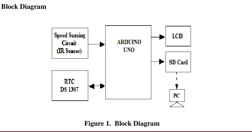
[image:3.595.88.521.542.769.2]2.1 Block Diagram
GE-INTERNATIONAL JOURNAL OF ENGINEERING RESEARCH
VOLUME -3, ISSUE -5 (May 2015) IF-4.007 ISSN: (2321-1717)
A Monthly Double-Blind Peer Reviewed Refereed Open Access International e-Journal - Included in the International Serial Directories. GE- International Journal of Engineering Research (GE-IJER)
Website: www.aarf.asia. Email: [email protected] , [email protected]
Page 142 The complete system for speed measurement using microcontroller can be explained
with the help of block diagram as shown in Fig. 1. It consists of five main blocks: Arduino
microcontroller, Speed Sensing Circuit, RTC, SD Card and LCD display [6]. The Speed
sensing circuit will count the number of rotations of the rotating disc and generate a pulse for
every rotation and these pulses are given as input to the microcontroller. The microcontroller
converts these pulses into rpm using a specific procedure. RTC chip keeps the record of real
time information during the sensing period that is the present date and time at which the
speed is being measured. Microcontroller now receives date, time and speed as the quantities
to be saved. The speed is written on SD card with real time clock stamp [7]. At the same time
the saved data is displayed on the LCD screen for instant monitoring. We have set the data
logging interval to be 1 minute. The collected data can then be imported to a spreadsheet
package such as Excel and statistical analysis can be carried out or graphs of the collected
data can easily be drawn [8].
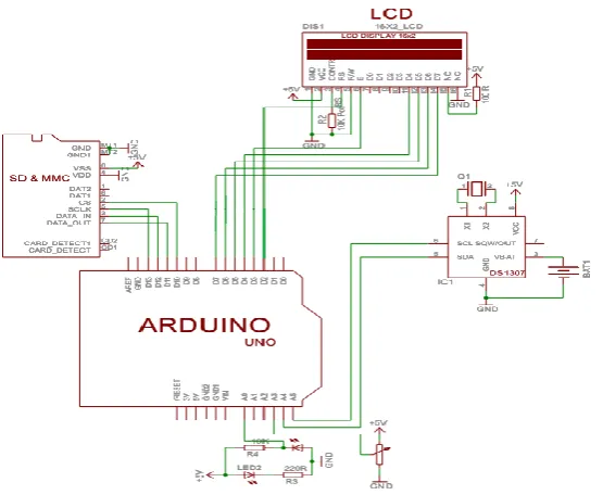
[image:4.595.162.440.393.621.2]2.2 Circuit Diagram
Figure 2. Circuit Diagram
The hardware connections for the above explained diagram can be explained as follows.
The IR transmitter is connected to 5V VCC and GND through 220 ohm resistor.
This IR signal is received by a photodiode connected at analog input A0 pin of Arduino. Also
SCL OUT and SDA pins of RTC DS1307 are connected to A5 and A4 pins of Arduino
GE-INTERNATIONAL JOURNAL OF ENGINEERING RESEARCH
VOLUME -3, ISSUE -5 (May 2015) IF-4.007 ISSN: (2321-1717)
A Monthly Double-Blind Peer Reviewed Refereed Open Access International e-Journal - Included in the International Serial Directories. GE- International Journal of Engineering Research (GE-IJER)
Website: www.aarf.asia. Email: [email protected] , [email protected]
Page 143 be received in the controller from the memory card through data out pin 7 of SD CARD
which is connected to D13 which is digital input pin of Arduino module [8]. Similarly data
can be sent to the memory card through pin D12 of Arduino which is connected to DATA IN,
pin 3 of SD Card module. The memory card can be selected using D10 pin connected to pin 2
of SD card. The LCD is connected using pins D2-D7. The necessary resistors required for the
working of LCD are as shown in circuit diagram. All the modules are connected to GND and
5V power supply as required.
3.METHODOLOGY
The software used to write code and upload it on to the board is Arduino IDE. The
open source Arduino environment makes it easy to write code and upload it to the board. It
runs on Windows, Mac OS X and Linux. The Arduino Uno can be programmed with the
Arduino software. Select "Arduino Uno from the Tools > Board menu (according to the
microcontroller on your board)..
The ATmega328 on the Arduino Uno comes preburned with a boot loader that allows
you to upload new code to it without the use of an external hardware programmer. It
communicates using the original STK500 protocol.
The algorithm for how the code of the program will work is as follows:
Step 1 Start of the main program on power up.
Step 2 Set the initial value of LCD.
Step 3 Set the initial value of RTC.
Step 4 Set the initial value of SD card.
Step 5 Check if SD card is inserted or not.
Step 6 If not, go to Function 1.
Step 7 Else display on LCD “SD card is inserted”.
Step 8 Start Timer1 for 1 minute.
Step 9 Count number of pulses.
Step 10 Stop counting when flag of Timer1 goes high.
Step 11 Call Function 2 to convert rpm into km/hr.
Step 12 Read date and time from RTC.
Step 13 Save the data (Date, Time, Speed) in SD card and save the file in “.csv” format.
GE-INTERNATIONAL JOURNAL OF ENGINEERING RESEARCH
VOLUME -3, ISSUE -5 (May 2015) IF-4.007 ISSN: (2321-1717)
A Monthly Double-Blind Peer Reviewed Refereed Open Access International e-Journal - Included in the International Serial Directories. GE- International Journal of Engineering Research (GE-IJER)
Website: www.aarf.asia. Email: [email protected] , [email protected]
Page 144
Function 1: Display on LCD “SD card not inserted”
Go to step 5.
Function 2: Read the value of rpm.
Speed = 2πr ×rpm ×60/1000 km/h.
Go to step 12.
At the beginning of the program port directions are configured and LCD and SD
card are initialized. The program then checks to find out whether the SD card is inserted, if
not, LCD displays “SD card not inserted”. When the device comes in run mode, RTC date
and time are read, speed data is read and then all of this data is written to the opened file in
the SD card.
4.CONCLUSION
a. The overall goal was to design and develop a system that can save the speed of the
vehicle with date and time. The system developed achieved this goal. It was compact in size
consumed little power and its only function was to save the data into SD card which can later
be retrieved. Presence of every module has been reasoned out and placed carefully, thus
contributing to the best working of the system. The system has been tested to function
automatically.
REFERENCES
[1] Arduino, “Arduini Uno” A000066 datasheet.
[2] S.V. Devika, Jayanth Thota and Khalesha Shaikh, “Arduino based automatic plant
watering system”, International Journal of Advanced Research in Computer Science and
Software Engineering, vol. 4, issue 10, October 2014.
[3] Campbell, J. Introduction to Remote Sensing, Second Edition, The Guilford Press, New
York, 1996.
[4] Dallas Semiconductor, “RTC” DS1307 datasheet.
[5] G. Mason, “A handheld data acquisition system for use in an undergraduate data
acquisition course,” Data acquisition, 45,2002, pp. 338-393.
[6] S. J. Pérez 1, M. A. Calva2 , R. Castañeda1, “A microcontroller based data logging
system”, Instrumentation and Development, Vol. 3 Nr. 8/1997.
[7] David R. Brooks, “Arduino based data loggers”, Hardware and software
GE-INTERNATIONAL JOURNAL OF ENGINEERING RESEARCH
VOLUME -3, ISSUE -5 (May 2015) IF-4.007 ISSN: (2321-1717)
A Monthly Double-Blind Peer Reviewed Refereed Open Access International e-Journal - Included in the International Serial Directories. GE- International Journal of Engineering Research (GE-IJER)
Website: www.aarf.asia. Email: [email protected] , [email protected]
Page 145 [8] Fraser, C. and J. Milne, Electro-Mechanical Engineering: An Integrated Approach, IEEE
Press, New York, NY, 1st Ed., 1994.
Negro V. C., “A Battery operated bubble memory data acquisition syatem”, IEEE