2018 International Conference on Modeling, Simulation and Optimization (MSO 2018) ISBN: 978-1-60595-542-1
A Simulator Framework for Naval Electronic Information System
Peng XU, Ling LI, Xiao-dong WANG, Geng LIU
and Ling-hao LI
System Engineering Research Institute of China State Shipbuilding Corporation, Beijing, China
Keywords: Software framework, Cooperative simulator, Main memory database (MMDB), Information system experiment, Radar simulator.
Abstract. Considering the frequent requirements for cooperative simulators in experiments of naval electronics information system and taking the expansibility of simulators and the portability of models into account, a simulator software framework for naval electronic information system is designed in this paper. The framework has a hierarchical structure, introduces the main memory database (MMDB), and a set of tools is designed in this framework to realize the major function of it. Based on the framework, the developing process of simulators is discussed; and taking the radar simulator as an example, the simulator is constructed to show the implementability and features of the framework.
Introduction
In the experiment of naval electronic information system, the experiment environment generally composes of several combat units, e.g. aircrafts and warships, and each combat unit needs to be equipped with a set of devices, e.g. sensor, navigator, timing system and command and control system to guarantee the normal conduct of information system experiment [1] . However, due to the restriction of experimental funds and place, it is hard to guarantee that the required devices are all ready for the experiment, and therefore it is necessary to develop corresponding simulators to substitute functions of devices or combat units which cannot take part into the experiment and to guarantee the normal conduct of functions and processes of information system to be tested[1].
With the rapid development of information technology, the naval electronic information systems of our country are also updating continuously. The requirements for the cooperative simulators would vary in the experiments as the naval electronic information system types are different, and therefore a set of newly developed simulators is needed for each information system type. Furthermore, as different requirements are continually made in the experiment, the cooperative simulators would be frequently modified as well, which means the simulators have inferior universality and reusability, causes large-scale waste of manpower and material resource, extends the development period and cannot fulfill experimental requirements in time. [2]
Given this situation, the functional requirements of cooperative simulators of naval electronic information system are extracted, the similarities of different simulators are abstracted to form a stable framework and the different parts of different simulators are abstracted and integrated into the framework in the form of configuration files or extensible components. Consequently, a mature mode with a stable framework as well as with different components or configurations is implemented to fulfill the experimental requirements of different types of naval electronic information systems.
Design of Cooperative Simulator Framework
Function of Cooperative Simulator Framework
The main function of cooperative simulator framework is to receive, display and store external network information, to process the existing information and generate new information based on relative algorithms and to transmit data to specified address.
information processing, external information storing, data processing algorithm, data display, data assembling and transmitting. For constructing a framework with scientific structure, the classic MVC architecture is employed and the main memory database (MMDB) is introduced. The information receiving, transmitting and storing functions are abstracted and incorporated into the simulator framework, and then the data processing algorithms, the data display, etc. are embedded in the framework as components to form a stable and extensible simulator framework.[3]
Structure Design of Cooperative Simulator Framework
The simulator framework for naval electronic information system includes a stable dispatching framework along with 3 tools by which the objective of quick simulator construction could be accomplished, i.e. the human-machine interface (HMI) designer, the framework configuration tool and the workflow designer.
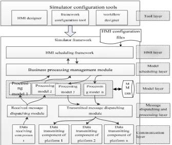
The simulator framework for naval electronic information system falls into the following layers which are also shown in Fig. 1, i.e. the communication layer, the message dispatching and processing layer, the model layer, the model scheduling layer, the HMI layer, the tool layer and the MMDB.
1) The communication layer encapsulates various communication modes and provides a unified communication call interfaces for upper layer, i.e. the initialization interface, the transmitting interface and the receiving interface.
2) The message dispatching and processing layer is responsible for formatting messages received from the communication layer, generating recognizable formatted messages, writing them to the MMDB and informing the business logic processing models require these formatted messages. Meanwhile, the layer is also responsible for accepting message transmitting requests submitted from the HMI layer or the business processing models, encapsulating messages to be transmitted and transmitting them to the communication layer. These messages would ultimately be transmitted by the communication layer.
3) The model layer is utilized to achieve specific business processing employing data processing algorithms to implement major simulator functions. The models are divided into single models and combined models; the combined model composes of several single models and could achieve complex processing functions.
4)The model scheduling layer provides triggering interfaces for the entire framework which include external message triggering interface, timer triggering interface and human-machine interaction triggering interface. This layer responds to external triggers and calls models from the model layer for business processing to accomplish the simulator functions.
5) The HMI layer is utilized to implement man-machine interaction in business process. This layer abstracts common simulator functions and extracts 3 universal HMI elements which are used for data display, function triggering and manual data input, i.e. display TOTE component, button component and input TOTE component.
6) The tools in the tool layer are utilized for simulator and workflow configuration. It provides convenient human-machine interaction where the HMI designer provides graphical interface to layout interface elements; the framework configuration tool achieves simulator initialization configuration; the workflow designer is responsible for model combination and it provides graphical tools to build business workflow.
Figure 1. Architecture of cooperative simulator framework.
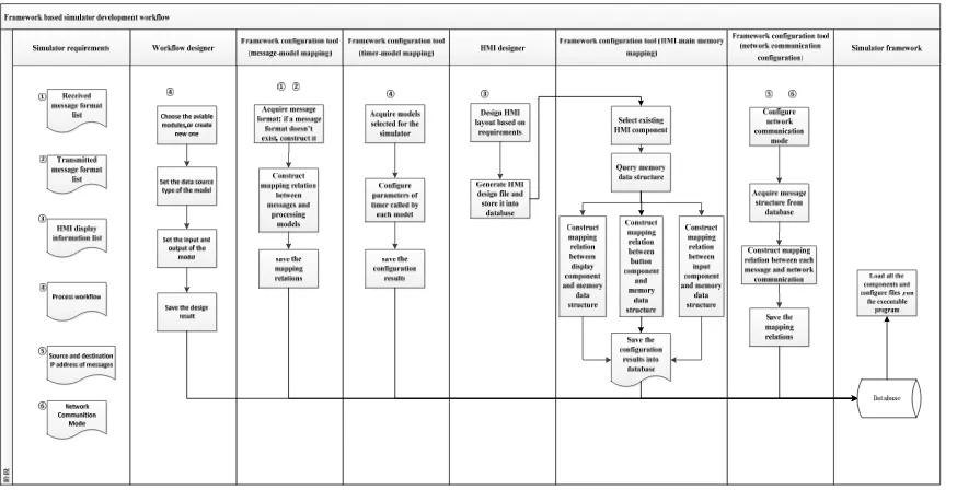
Cooperative Simulator Developing Process Based on the Framework
On the basis of the cooperative simulator framework, different tools are employed and the existing message models, business processing models and model scheduling interface, etc. are adequately reused to rapidly configure and generate simulators fulfilling requirements.
There are 5 extensible parts in the simulator framework, i.e. message type, business processing model, model scheduling interface, message transmitting and receiving address and HMI. The simulator developing process is to extend and reassemble these extensible parts.
Figure 2. Cooperative simulator developing process based on simulator framework.
Figure 3. Interface relationship between the radar simulator and the other simulators.
Information Format Storing into Database
1) Message format storing. If the message format doesn’t exist in the database, it would be stored into the database according to the message receiving and transmitting requirement.
2) Other data format storing. The data format that should be saved during business processing and human-machine interaction would be stored into the database.
3) Configuration format storing. The format of configuration information required by the simulator would also be stored into the database.
4) For the radar simulator, the information to be stored into the database is shown in Table 1. Table 1. Information to be stored for the radar simulator.
Information type Information specification
Simulation situation information
Simulation situation information is generated by console scenario executing and includes real-time location and motion information of platforms. Simulation control
information
Simulation control information is the messages utilized to control the boot, pause and termination of each simulator.
Timing information Timing information is the timing code utilized for clock synchronization of each simulator.
Navigation information Navigation information is utilized to simulate the navigation data of the platform where the radar locates.
Business Model Design
Business model design is to combine a series of models to achieve complex business logic. By means of the workflow designer, the models, database data and the input and output of models involved in the business logic processing are all configured, and the business logic processing scheme are finally generated.
Through parsing the scheme mentioned above, the model scheduling interface executes corresponding model logic processing, and stores the processing results into the database or transmitted them by a proper way.
There is a unique entry as the call interface for a single model or a combined model.
[image:5.612.78.533.232.558.2]A typical radar simulator composes of the single models and the combined models which are described in Table 2.
Table 2. Constituent models of a typical radar simulator.
Model designation Model function
Simulation situation
information processing model This model is to parse the received simulation situation information and to store the information into the MMDB. Simulation control
information processing model This model is to receive simulation control information and to boot, suspend and terminate corresponding functions of the entire simulator. Timing information processing
model This model is to receive the timing information and to modify the local machine time. Navigation information
processing model
This model is to parse the received navigation information and to store the information into the MMDB.
Radar parameter modification model
This model is to acquire parameters input from the HMI, e.g. radar detection range, detection error and scan cycle and to store these parameters into the
MMDB.
Radar track generating model
According to the navigation information, simulation information and radar parameters in the MMDB, this model calculates and filters out target list that could be detected in this scan cycle employing the classical radar equation and
stores the target list into corresponding table in the MMDB. Radar track maintenance
model
This model is to maintain the existing radar track information in the MMDB, e.g. delete expired track information.
Radar track transmitting
model This model is to transmit radar track information based on configured rules.
Simulation situation
acquisition model This model is to acquire simulation situation information from the MMDB.
Timing information
acquisition model This model is to acquire timing information from the MMDB.
Navigation information
acquisition model This model is to acquire navigation information from the MMDB.
Radar track acquisition model This model is to acquire radar track information from the MMDB.
Where the radar track generating model would be configured employing the workflow designer to confirm its input and output. The detailed design is shown as Figure 4.
[image:5.612.123.495.571.727.2]Message Processing Model Mapping Configuration
The mapping relation is established between each message to be received and corresponding processing model to guarantee the corresponding processing model can be triggered after each message being received. Then the mapping relation is stored.
[image:6.612.82.522.160.225.2]For the radar simulator, the mapping relations are shown in Table 3.
Table 3. Mapping relations between messages and corresponding processing models.
Message designation Model designation
Simulation situation information Simulation situation information processing model
Simulation control information Simulation control information processing model
Timing information Timing information processing model
Navigation information Navigation information processing model
Timer Mapping Configuration
The mapping relation is established between model requires to be called periodically and timer to guarantee the model can be called timely. Timer parameters, e.g. timer cycle are configured at the same time.
For the radar simulator, the timer mapping relations are shown in Table 4. Table 4. Timer mapping relations.
Timer designation Model designation
Timer 1 Radar track generating model
Timer 2 Radar track maintenance model
Timer 3 Radar track transmitting model
Timer 4 Navigation information processing model
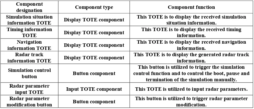
HMI Design
The HMI design is achieved employing the HMI designer. Appreciate display TOTE components, button components and input TOTE components are selected then laid out to form the simulator HMI. The results would be stored after the design.
For the radar simulator, the components included in the HMI are shown in Table 5. Table 5. Components included in the radar simulator HMI.
Component
designation Component type Component function
Simulation situation
information TOTE Display TOTE component This TOTE is to display the received simulation situation information. Timing information
TOTE Display TOTE component This TOTE is to display the received timing information.
Navigation
information TOTE Display TOTE component This TOTE is to display the received navigation information. Radar track
information TOTE Display TOTE component This TOTE is to display the generated radar track information. Simulation control
button Button component
This button is utilized to trigger the simulation control function and to control the boot, pause and
termination of the simulation manually. Radar parameter
input TOTE Input TOTE component This TOTE is utilized to input radar parameters.
Radar parameter
modification button Button component This button is utilized to trigger radar parameter modification.
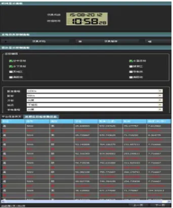
[image:6.612.84.529.482.673.2]Figure 5. Radar simulator HMI layout.
HMI Mapping Configuration
1) The mapping relation between HMI trigger button and model to be called is established.
2) The mapping relation between HMI display TOTE component and corresponding data format is established.
3) The mapping relation between HMI input TOTE component and corresponding data format is established.
4) The mapping relations mentioned above are stored.
[image:7.612.222.393.65.271.2]5) For the radar simulator, the mapping relations between HMI components and corresponding processing models are shown in Table 6.
Table 6. HMI mapping relations.
HMI component designation Model designation
Simulation situation information TOTE Simulation situation information acquisition model
Timing information TOTE Timing information acquisition model
Navigation information TOTE Navigation information acquisition model
Radar track information TOTE Radar track acquisition model
Simulation control button Simulation control information processing model
Radar parameter input TOTE
Radar parameter modification model Radar parameter modification button
Network Communication Configuration
The appreciate communication mode and corresponding communication parameters are configured. The transmitting interface (e.g. socket and region) and IP address of each transmitted message are configured.
For the radar simulator, the configured simulator IP addresses are shown in Table 7. Table 7. IP address for each simulator.
Simulator IP address
Console 192.168.1.1
Navigation simulator 192.168.1.2
Timing simulator 192.168.1.3
Radar simulator 192.168.1.4
Command and control simulator 192.168.1.5
[image:7.612.84.529.440.546.2]Table 8. Mapping relation between message and IP address.
Transmitted message type IP address of transmitting socket Destination address
Radar track information 192.168.1.4 192.168.1.5
Simulator Integration and Running
The simulator framework reads the configuration information already configured from database and calls corresponding models to guarantee the normal operation of the simulator.
Conclusion
The verification of the cooperative simulator framework for naval electronic information system demonstrates that the function extension of simulator can be achieved by modifying configuration and extending models and the simulator framework application can achieve reuse of existing messages and models as well as rapid building of new simulators to provide cooperative solutions for naval electronic information system experiments rapidly. Furthermore, this framework could be applied as the framework foundation of application software development to other fields.
References
[1] Fang Can-xin, Zhao Zheng-hai, Si Zhong-yi, Design and implementation of ship combat command system testing platform, Computer Engineering and Design. Vol. 29. No. 10(2008)2640-2642.
[2] Zhang Jingping, Simulation Model Systems of Sea Battle, Ship Electronic Engineering. Vol. 36. No. 2(2016)5-7.