University of Huddersfield Repository
Zhang, Hongyu
The Influence of Stem Design and Fixation Methods on the Lifetime of Total Hip Replacement
Original Citation
Zhang, Hongyu (2009) The Influence of Stem Design and Fixation Methods on the Lifetime of
Total Hip Replacement. Doctoral thesis, University of Huddersfield.
This version is available at http://eprints.hud.ac.uk/id/eprint/6965/
The University Repository is a digital collection of the research output of the
University, available on Open Access. Copyright and Moral Rights for the items
on this site are retained by the individual author and/or other copyright owners.
Users may access full items free of charge; copies of full text items generally
can be reproduced, displayed or performed and given to third parties in any
format or medium for personal research or study, educational or notforprofit
purposes without prior permission or charge, provided:
•
The authors, title and full bibliographic details is credited in any copy;
•
A hyperlink and/or URL is included for the original metadata page; and
•
The content is not changed in any way.
For more information, including our policy and submission procedure, please
contact the Repository Team at: [email protected].
The Influence of Stem Design and Fixation Methods
on the Lifetime of Total Hip Replacement
Hongyu
Zhang
Direct Supervisor: Professor Liam Blunt
Centre for Precision Technologies
School of Computing and Engineering
University of Huddersfield
A thesis submitted to the University of Huddersfield in accordance with
the requirements for the degree of Doctor of Philosophy
Abstract
Total hip replacement is one of the most common surgical procedures performed both in the UK and worldwide, with aseptic loosening cited as the primary reason for revision. Aseptic loosening is attributed to the wear debris generated by wear of the components. Recently, as great progress has been achieved in reducing wear at the head–cup interface, there has been a shift of research interest to other load bearing surfaces.
The main purpose of this thesis is to study fretting wear mechanisms at the polished femoral stem– bone cement interface.
The initial studies have investigated the bond strength at the stem–cement interface using seven brands of bone cement and femoral stems with different surface finishes. It can be confirmed that debonding at this interface is inevitable, which subsequently facilitates generation of fretting wear on the stem surface.
A new test methodology has been developed to reproduce fretting wear clinically seen on polished stems through in vitro wear simulations, and it shows great success in comparison with previous attempts. In addition, migration of the stem within the cement mantle has been investigated, and it has been indicated that the simulation setup more realistically mimics clinical situations.
Acknowledgements
I would firstly like to thank my director of studies Prof. Liam Blunt for his great supervision and professional guidance during this research. I am most indebted to him and I am deeply impressed by his erudition in knowledge and attitude in science which promote me to keep on going.
I would also like to show my grateful appreciation to the other members of the supervisory team, Prof. Xiang qian (Jane) Jiang, Dr. Leigh Brown and Dr. Simon Barrans for their continuous suggestions and aspiring assistance, which are certainly one of the key elements in the completion of this thesis.
Additionally, I would like to express my deepest thanks to Dr. Shaojun Xiao, Dr. Feng Xie, Dr. Paul Bills, Dr. Philip Harrison, and Mr. Allan Kennedy, Centre for Precision Technologies, School of Computing and Engineering, The University of Huddersfield, who have been so supportive over the years.
From a more practical view, Mr. Peter Norman, Mr. Dennis Town and other technicians, School of Computing and Engineering, The University of Huddersfield, have provided substantial technical assistance throughout the duration of this research. I would like to thank them from the bottom of my heart.
Many thanks are due for the support from Mr. Ian Johnson and Dr. Howard Williams, School of Applied Science, The University of Huddersfield, who trained me on scanning electron microscopy and provided me an access whenever available.
Abstract...1
Acknowledgements ...2
List of figures...7
List of tables...13
Abbreviations ...14
Chapter 1 Introduction...15
1.1 Project background... 15
1.1.1 Total hip replacement ...15
1.1.2 Failure of total hip replacement ...16
1.1.3 The stem–cement interface ...17
1.2 Project aims and objectives ... 18
1.2.1 Aims...18
1.2.2 Objectives ...18
Chapter 2 Total hip replacement ...20
2.1 Chapter summary ... 20
2.2 The loading regime of the hip joint ... 20
2.2.1 Anatomy of the hip ...20
2.2.2 Hip joint force...22
2.3 Uncemented and cemented total hip replacement ... 23
2.3.1 Uncemented total hip replacement...23
2.3.2 Cemented total hip replacement...24
2.4 Metal femoral stem ... 25
2.4.1 General introduction ...25
2.4.2 Design properties ...27
2.5 Acrylic bone cement ... 29
2.5.1 General introduction ...29
2.5.2 Mechanical and physical properties...31
2.5.3 Current controversies ...33
2.6 Failure mechanisms of cemented total hip replacement... 34
2.6.1 General introduction ...34
2.6.2 Wear debris induced bone resorption...35
2.6.3 Stress shielding ...36
2.7 Wear at the stem–cement interface ... 37
2.7.1 General introduction ...37
2.7.2 Evidence of wear on the stem ...38
2.7.3 Wear mechanism at the stem–cement interface ...39
2.8 Fretting wear and in vitro simulation ... 42
2.8.1 Fretting wear ...42
2.8.2 In vitro simulation of fretting wear ...43
Chapter 3 Metrology strategy ...45
3.1 Chapter summary ... 45
3.2 The challenge for metrology in hip orthopaedic industry ... 45
3.2.1 The head–cup interface ...45
3.2.3 Summary...47
3.3 Instrumentation employed throughout the research of the project ... 47
3.3.1 Contacting stylus measurement—Talysurf PGI Series 2...48
3.3.2 Non-contacting optical measurement—Talysurf CCI 3000...49
3.3.3 Scanning electron microscope—JEOL JSM–6060...51
3.4 Characterisation technology ... 54
3.4.1 The limitations of 2D surface characterisation ...54
3.4.2 3D surface characterisation...55
Chapter 4 The stem–cement interfacial strength...57
4.1 Chapter summary ... 57
4.2 The stem–cement interfacial gap ... 57
4.2.1 Background and aims...57
4.2.2 Materials and methods ...58
4.2.3 Results and discussion ...59
4.2.4 Conclusions...60
4.3 Interfacial strength between polished stem and bone cements ... 60
4.3.1 Background and aims...60
4.3.2 Materials and methods ...61
4.3.3 Results...65
4.3.4 Discussion...72
4.3.5 Conclusions...73
4.4 Influence of stem surface finish on stem–cement interfacial strength... 74
4.4.1 Background and aims...74
4.4.2 Materials and methods ...74
4.4.3 Results...76
4.4.4 Discussion...82
4.4.5 Conclusions...84
4.5 Summary... 84
Chapter 5 Reproduction of fretting wear on the femoral stem...86
5.1 Chapter summary ... 86
5.2 Initial attempt to replicate fretting wear at the stem–cement interface (Simulation I)... 86
5.2.1 Background and aims...86
5.2.2 Materials and methods ...87
5.2.3 Results...90
5.2.4 Discussion...98
5.2.5 Conclusions...99
5.3 Consistent reproduction of fretting wear at the stem–cement interface (Simulation II) ... 100
5.3.1 Background and methods...100
5.3.2 Results...100
5.3.3 Discussion...104
5.4 Summary of the in vitro wear simulations ... 105
6.1 Chapter summary ... 106
6.2 Investigation of relative micromotion at the stem–cement interface (Simulation III) ... 106
6.2.1 Background and aims...106
6.2.2 Materials and methods ...107
6.2.3 Results...109
6.2.4 Discussion...112
6.2.5 Conclusions...114
6.3 Summary... 114
Chapter 7 Factors influencing fretting wear on the femoral stem ... 115
7.1 Chapter summary ... 115
7.2 Influence of the duration of in vivo service of the hip prosthesis on generation of fretting wear (Simulation IV)... 115
7.2.1 Background and methods...115
7.2.2 Results and discussion ...116
7.2.3 Conclusions...121
7.3 Influence of bone cement brand on generation of fretting wear (Simulation V to VIII)... 121
7.3.1 Background and aims...121
7.3.2 Materials and methods ...121
7.3.2 Results...122
7.3.3 Discussion...134
7.3.4 Conclusions...136
7.4 A summary of all the in vitro wear simulations completed (from Simulation I to VIII, see Appendix IV)... 136
Chapter 8 Initiation and propagation of fretting wear on the femoral stem...137
8.1 Chapter summary ... 137
8.2 Finite element analysis of the stem–cement interface ... 137
8.2.1 Background and aims...137
8.2.2 Methods ...138
8.2.3 Results...141
8.2.4 Discussion...148
8.2.5 Conclusions...150
8.3 Summary... 150
Chapter 9 Discussion ...151
Chapter 10 Conclusions...154
Chapter 11 Future studies ...155
11.1 Investigation of the influence of storage condition of bone cement on its mechanical properties and long term performance ... 155
11.2 Investigation of the influence of stem geometry and surface finish on generation of fretting wear ... 155
11.3 Development of a method to evaluate the wear debris at the stem–cement interface... 156
11.5 More detailed study of FEA techniques to investigate the stem–cement interface
... 156
References ...158
Appendix I ...167
Three-way ANOVA of static shear strength, interfacial porosity, and micropore size for bone cements (Section 4.3)... 167
Appendix II...168
Unpaired student t-test between Simplex P and Simplex P–T (Section 4.3)... 168
Appendix III ...168
One-way ANOVA of interfacial strength and Tukey–Kramer Post Hoc Test for different surface finish rods (Section 4.4) ... 168
Appendix IV ...169
Summary of the in vitro wear simulations to reproduce fretting wear at the stem– cement interface ... 169
Appendix V ...170
3D surface topography of the worn areas of Gruen zones 6 and 7 on the femoral stem in simulation I (Section 5.2)... 170
Appendix VI ...171
Surface topography of fretting zone on the femoral stem from Simulation I measured utilising scanning electron microscope (Section 5.2)... 171
Appendix VII ...171
Fretting wear scar generated on the femoral stem from Simulation II (Section 5.3) 171
Appendix VIII ...172
Calibration of the new custom-made micromotion sensor (Section 6.2)... 172
Appendix IX ...172
One-way ANOVA of 3D surface parameters of the fretting zones on the stem (Section 7.2) ... 172
Appendix X ...173
Microhardness test of the bone cements from the in vitro wear simulations (Section 7.3) ... 173
Appendix XI ...174
Shrinkage bumps present on Simplex P and Coriplast 3 bone cements following polymerisation (Section 8.3) ... 174
Appendix XII...174
List of figures
Figure 1.1: (a) Osteoarthritis at the hip (b) Total hip replacement with a metal prosthesis Figure 1.2: (a) Uncemented total hip replacement (b) Cemented total hip replacement Figure 1.3: Typical periprosthetic bone resorption
Figure 2.1: The structure of a natural hip
Figure 2.2: Definition of degree of freedom of hip motions
Figure 2.3: Hip joint reaction force in terms of body weight through one walking cycle (1) Vertical force (2) Entraining velocity (Paul 1967)
Figure 2.4: Typical procedures of total hip replacement Figure 2.5: Different designs of femoral implants
Figure 2.6: (a) Example of a modular femoral stem design—Exeter (b) Example of a monoblock femoral stem design—Charnley
Figure 2.7: Load transfer patterns (a) Within the natural femur (b) Around the C stem
Figure 2.8: The formation of polymer chains (a) Radical for initiation of polymerisation and MMA monomer (b) Growing polymer chain with reactive site at the end (c) Final polymer molecule
Figure 2.9: Fractures present in bone cement mantle: c=cement; p=prosthesis; b=bone Figure 2.10: Reasons for revision of THR (a) Stem fracture (b) Prosthesis dislocation
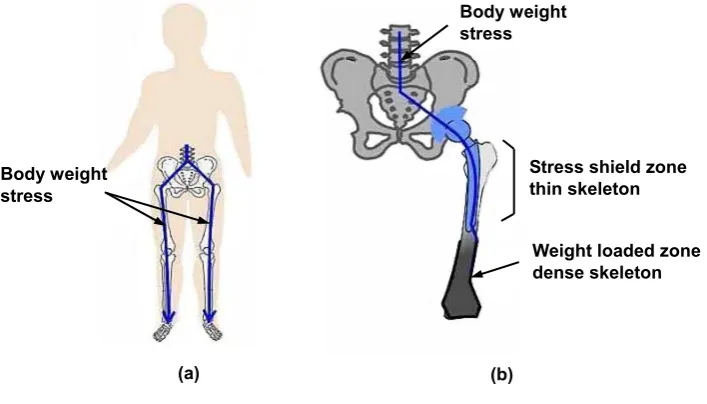
Figure 2.11: Migration of wear debris to bone tissues through gaps at the stem–cement interface Figure 2.12: Effect of stress shielding
Figure 2.13: Evidence of abrasive wear present on matt Exeter femoral stems
Figure 2.14: Fretting wear on an explanted polished Exeter femoral stem measured by SEM Figure 2.15: Grazing incidence SEM images showing increasing degrees of polishing wear on
matt-surfaced stems (a) An unworn area (b) An area of slight polishing wear (c) An area of marked polishing wear (Howell et al. 2004)
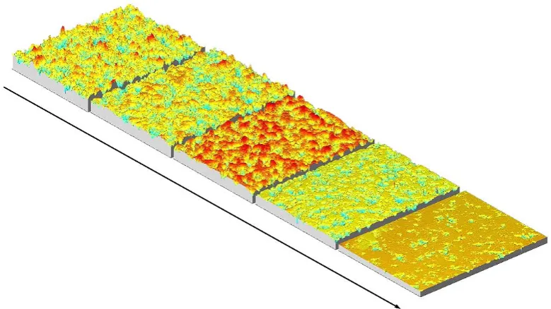
Figure 2.16: The axonometric plots showing progressive stages of abrasive wear on an Exeter matt-surfaced stem, the asperities present on the unworn surface are removed during the wear process (Brown 2006)
Figure 2.17: The schematic appearance of fretting damage on metal surfaces
Figure 2.18: (a) The model of simplified pin-on-plate device, the arrows show axial force on the pin and sliding motion of the plate (b) The model of simplified pin-on-disk device, the arrows show axial force on the pin and rotating motion of the disk
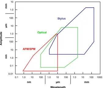
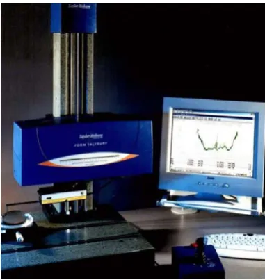
Figure 3.1: The plot showing range and resolution for the available measurement techniques Figure 3.2: The schematic diagram showing the principle of RCHD grating transducer Figure 3.3: The contacting stylus measurement instrument—Talysurf PGI
Figure 3.4: The non-contacting optical measurement instrument—Talysurf CCI 3000 Figure 3.5: The basic principle showing how Talysurf CCI 3000 works
Figure 3.6: The schematic diagram showing the main components of a scanning electron microscope
Figure 3.7: Various signals generated by the interaction between the electron beam and the specimen
Figure 3.8: The scanning electron microscope—JEOL JSM–6060
Figure 3.10: A 2D trace taken from an areal surface measurement shows the ambiguity of 2D surface characterisation
Figure 3.11: The 3D field parameter set to describe functional performance of a surface Figure 4.1: The schematic diagram to describe the steps to prepare the experimental specimen Figure 4.2: The experimental specimen to test fluid flow along the stem–cement interface Figure 4.3: Observation of the blue ink at the bottom of the shot-blasted stainless steel rod Figure 4.4: (a) Dimension of the stainless steel rods (b) Design of the steel holder
Figure 4.5: Preparation of specimen using a milling machine chuck to ensure axial positioning Figure 4.6: Set up of pull out test on a Hounsfield Test Machine H20K–W
Figure 4.7: The Leica optical stereomicroscope
Figure 4.8: Micropores detection based on grey scale threshold (a) Original image (b) Detected image
Figure 4.9: The model of three-way analysis of variance
Figure 4.10: Static shear strength for the 12mm diameter stainless steel rod Figure 4.11: Interfacial porosity for the 12mm diameter stainless steel rod
Figure 4.12: Micropore size at the interface for the 12mm diameter stainless steel rod Figure 4.13: Static shear strength for the 8mm diameter stainless steel rod
Figure 4.14: Interfacial porosity for the 8mm diameter stainless steel rod
Figure 4.15: Micropore size at the interface for the 8mm diameter stainless steel rod Figure 4.16: A typical load–displacement plot for the pull out test
Figure 4.17: (a) Pull out test performed on Instron Test Machine (b) Transfer films on the rod surface
Figure 4.18: (a) Transfer films detected for CMW 3 bone cement in the pull out test by Instron (b) 2D profile showing height of transfer films for CMW 3 bone cement in a pull out test by Instron
Figure 4.19: The flow diagram showing the pull out process of the rod from the cement mantle Figure 4.20: Pull out test of a cylindrical fibre from a resin disk (a) The fibre embedded in the
resin disk (b) Typical load–displacement curve
Figure 4.21: (a) Transfer films detected for CMW 3 bone cement in a pull out test by Hounsfield (b) 2D profile showing height of transfer films for CMW 3 bone cement in a pull out test by Hounsfield
Figure 4.22: 3D surface topography of stainless steel rods before pull out test (a) Polished (b) Glass bead-blasted (c) Shot-blasted (d) Grit-blasted
Figure 4.23: Interfacial strength between Simplex P bone cement and different surface finish rods Figure 4.24: Typical load–displacement plot for pull out test of glass bead-blasted stainless steel
rods
Figure 4.25: Typical load–displacement plot for pull out test of shot-blasted stainless steel rods Figure 4.26: Typical load–displacement plot for pull out test of grit-blasted stainless steel rods Figure 4.27: Stainless steel rod surface after pull out test (a) Polished rod, the black substrate is the
Figure 4.28: Micropores formed in the cement surface interfaced with polished rods Figure 4.29: 3D surface topography of bone cement interfaced with stainless steel rods (a)
Polished (b) Glass bead-blasted (c) Shot-blasted (d) Grit-blasted
Figure 4.30: Metallic debris embedding within the cement mantle originating from the grit-blasted rod pull out test
Figure 5.1: Preparation of specimen for fretting wear simulation
Figure 5.2: Oscilloscope displaying the sine wave force applied to femoral head (Channel 1) and the corresponding displacement of the experimental specimen (Channel 2) of Instron test machine
Figure 5.3: Definition of Gruen zones of the stem surface
Figure 5.4: The grid coordinate system to relocate the position of femoral stem
Figure 5.5: Validation of the relocation system by two measurements taken at different time Figure 5.6: Fretting wear generated on the femoral stem surface (Simulation I, use Simplex P
cement)
Figure 5.7: Detection of worn areas on the stem surface based on grey scale threshold
Figure 5.8: Change of stem surface at the same position pre and post simulation (Simulation I, use Simplex P cement)
Figure 5.9: (a) Comparison of fretting wear area and undamaged area on the femoral stem (b) 2D surface topography of the worn areas (Simulation I, use Simplex P cement)
Figure 5.10: The thresholding process to remove potential wear debris above the original stem surface
Figure 5.11: Histogram showing change of Sq pre and post simulation of selected area on the stem Figure 5.12: Histogram showing change of Sz pre and post simulation of selected area on the stem Figure 5.13: Histogram showing change of Sdq pre and post simulation of selected area on the
stem
Figure 5.14: Histogram showing change of Sdr pre and post simulation of selected area on the stem
Figure 5.15: Comparison of fretting zones between (a) Simulated Exeter femoral stem and (b) Explanted Exeter femoral stem (Simulation I, use Simplex P cement) (two micrographs at optimal magnification to show fretting effects)
Figure 5.16: Comparison of worn and unworn areas on the Simplex P cement surface (Simulation I)
Figure 5.17: (a) SEM micrograph showing fretting debris located in the micropores (b) Corresponding EDX analysis (Simulation I, use Simplex P cement)
Figure 5.18: (a) Optical micrograph showing “undamaged islands” on the stem surface and (b) Corresponding micropores in the cement surface (Simulation I, use Simplex P cement)
Figure 5.19: Initiation of fretting wear on the stem surface and micropores in the cement surface (Simulation II, use Simplex P cement)
Figure 5.20: Initiation of fretting wear on the stem surface and micropores in the cement surface (Simulation II, use Simplex P cement)
Figure 5.22: (a) Interferometric micrograph of the worn areas showing propagation of fretting wear on the stem surface (b) 2D surface topography of the worn areas (Simulation II, use Simplex P cement)
Figure 5.23: The maximum and minimum position of the experimental specimen, note that the dashed line is fitted according to the tendency of the data (Simulation II, use Simplex P cement)
Figure 5.24: Shrinkage bumps on the cement surface following polymerisation and its 2D profile Figure 6.1: The schematic diagram showing the principle of the micromotion sensor
Figure 6.2: Calibration of the micromotion sensor using the extensometer
Figure 6.3: The curve fitted using Least Squares Analysis based on the recorded data Figure 6.4: The experimental specimen prepared for the present simulation
Figure 6.5: Migration of the polished Exeter stem within the cement mantle, the curves (a) and (b) correspond to the maximum and minimum values of the compressive loading
respectively
Figure 6.6: Generation of typical fretting pits on the femoral stem surface (Simulation III) Figure 6.7: Initiation of fretting wear on the stem surface and micropores in the cement surface
(Simulation III)
Figure 6.8: The femoral stem and bone cement surfaces after simulation demonstrating an evident relationship between fretting wear damage and unworn areas on the stem surface and corresponding contact areas on the cement surface (Simulation III)
Figure 7.1: Fretting wear generated on the femoral stem surface (Simulation IV, use Simplex P cement)
Figure 7.2: Talysurf CCI measurement of worn areas on the stem surface (Simulation IV, use Simplex P cement)
Figure 7.3: Comparison of 3D surface parameters of the worn areas on the femoral stem between two wear simulations (Simulation I and Simulation IV)
Figure 7.4: Optical micrograph of cement surface showing the highly reflective sites around the micropores (Simulation IV, use Simplex P cement)
Figure 7.5: (a) SEM micrograph of the micropores in the cement surface (b) EDX analysis (Simulation IV, use Simplex P cement)
Figure 7.6: Micro-cracks initiated at the edge of the micropores in the Simplex P cement surface (Simulation IV)
Figure 7.7: Magnification of the two micro-cracks in figure 7.6
Figure 7.8: Optical micrograph showing undamaged areas on the stem surface and micropores in the cement surface (Simulation IV, use Simplex P cement)
Figure 7.9: The Micromet 2101 microhardness tester
Figure 7.10: Fretting wear generated on the femoral stem surface (Simulation V, use CMW 3 cement)
Figure 7.11: Fretting wear generated on the femoral stem surface (Simulation VI, use CMW 3 cement)
CMW 3 cement)
Figure 7.14: Initiation of fretting wear on the stem surface and micropores in the cement surface (Simulation V, use CMW 3 cement)
Figure 7.15: Propagation of fretting wear on the stem surface and micropores in the cement surface (Simulation V, use CMW 3 cement)
Figure 7.16: Initiation of fretting wear on the stem surface and micropores in the cement surface (Simulation VI, use CMW 3 cement)
Figure 7.17: Propagation of fretting wear on the stem surface and micropores in the cement surface (Simulation VI, use CMW 3 cement)
Figure 7.18: Optical micrograph of cement surface showing areas of potential metallic debris around the micropores (Simulation V, use CMW 3 cement)
Figure 7.19: (a) SEM micrograph of the micropores in the cement surface (b) EDX analysis (Simulation V, use CMW 3 cement)
Figure 7.20: Optical micrograph of cement surface showing areas of potential metallic debris around the micropores (Simulation VI, use CMW 3 cement)
Figure 7.21: (a) SEM micrograph of the micropores in the cement surface (b) EDX analysis (Simulation VI, use CMW 3 cement)
Figure 7.22: Fretting wear generated on the femoral stem surface (Simulation VII, use Palacos R cement)
Figure 7.23: Fretting wear generated on the femoral stem surface (Simulation VIII, use Palacos R cement)
Figure 7.24: Comparison of fretting wear area and undamaged area on the femoral stem (Simulation VII, use Palacos R cement)
Figure 7.25: Comparison of fretting wear area and undamaged area on the femoral stem (Simulation VIII, use Palacos R cement)
Figure 7.26: Optical micrograph showing undamaged areas on the stem surface and micropores in the cement surface (Simulation VII, use Palacos R cement)
Figure 7.27: Optical micrograph showing undamaged areas on the stem surface and micropores in the cement surface (Simulation VIII, use Palacos R cement)
Figure 7.28: Optical micrograph of cement surface showing areas of potential metallic debris around the micropores (Simulation VII, use Palacos R cement)
Figure 7.29: (a) SEM micrograph of the micropores in the cement surface (b) EDX analysis (Simulation VII, use Palacos R cement)
Figure 7.30: Optical micrograph of cement surface showing areas of potential metallic debris around the micropores (Simulation VIII, use Palacos R cement)
Figure 7.31: (a) SEM micrograph of the micropores in the cement surface (b) EDX analysis (Simulation VIII, use Palacos R cement)
Figure 8.1: Shrinkage bumps present on the common bone cement surfaces following
polymerisation (a) Simplex P with tobramycin (b) Palacos R (c) CMW 1 (d) CMW 3 Figure 8.2: 2D finite element model simulating the interaction between the stem and the bumps Figure 8.3: 2D finite element model simulating the interaction between the stem and the
micropores
bumps when pressing the stem to the cement (a) The stem and the bumps contact without any deformation (b) The bumps are badly deformed upon loading (c) There exits a gap at the edge of the bumps (d) The stem and the bumps are in full contact Figure 8.5: The relative micromotion along the stem–cement interface between the stem and the
shrinkage bumps
Figure 8.6: The contact pressure normal to the cement surface between the stem and the shrinkage bumps
Figure 8.7: The schematic diagram showing the interaction between the stem and the micropore (1) when pressing the stem to the cement
Figure 8.8: The relative micromotion along the stem–cement interface between the stem and the micropores
Figure 8.9: The contact pressure normal to the cement surface between the stem and the micropores
Figure 8.10: The maximum relative micromotion along the stem–cement interface between the stem and the micropores with different sizes. The red line shows the tendency for micropore (1) and the blue line shows the tendency for micropore (2)
Figure 8.11: The maximum contact pressure normal to the cement surface between the stem and the micropores with different sizes
Figure 8.12: The maximum relative micromotion along the stem–cement interface between the stem and micropores with different loading levels, the red line shows the tendency for micropore (1) and the blue line shows the tendency for micropore (2)
Figure 8.13: The maximum contact pressure normal to the cement surface between the stem and the micropores with different loading levels
List of tables
Table 2.1: The three degrees of freedom of the hip joint
Table 2.2: Typical studies on hip joint forces during different human normal activities Table 2.3: The five most commonly used bone cements
Table 2.4: Typical characteristics of three generations of cementing techniques Table 3.1: The typical specifications of Talysurf PGI Series 2
Table 3.2: The typical specifications of Talysurf CCI 3000 Table 3.3: The typical specifications of JEOL JSM–6060
Table 4.1: Relative viscosity and composition of the seven commercial PMMA bone cements Table 4.2: Static shear strength, porosity, and micropore size for each cement brand (mean±std) Table 4.3: Expatiation of 3D surface parameters to assess a surface in height deviation
Table 4.4: 3D surface parameters of stainless steel rods with differing surface finishes (mean±std) Table 4.5: 3D surface parameters of bone cement interfaced with the four kinds of surface finish
rod (mean±std)
Table 5.1: A summary of the instruments used to analyse femoral stem wear
Table 5.2: Coverage of fretting wear area in each Gruen zone on the stem surface (%)— Simulation I, use Simplex P cement
Table 5.3: The maximum and minimum position of the experimental specimen—Simulation II, use Simplex P cement
Table 7.1: Coverage of fretting wear area in each Gruen zone on the stem surface (%)— Simulation IV, use Simplex P cement
Table 7.2: Elemental composition of the wear debris at the edge of the micropores (%, m/m)— Simulation IV, use Simplex P cement
Table 7.3: Chemical composition of stainless steel REX 734 specified in BS 7252–9 (%, m/m) Table 7.4: Coverage of fretting wear area in each Gruen zone on the stem surface (%)—
Simulation V, use CMW 3 cement
Table 7.5: Coverage of fretting wear area in each Gruen zone on the stem surface (%)— Simulation VI, use CMW 3 cement
Table 7.6: Coverage of fretting wear area in each Gruen zone on the stem surface (%)— Simulation VII, use Palacos R cement
Table 7.7: Coverage of fretting wear area in each Gruen zone on the stem surface (%)— Simulation VIII, use Palacos R cement
Abbreviations
ANOVA: analysis of variance BEI: backscattered electron image BPO: benzoylperoxide
BW: body weight
CCI: coherence correlation interferometer CRT: cathode ray tube
DMPT: dimethyl para toluidine EDM: electrical discharge machining EDX: energy dispersive X–ray EU: European Union
FEA: finite element analysis HA: hydroxyapatite
HQ: hydroquinone
HV: Vickers microhardness
LVDT: linear variable differential transformer MMA: methylmethacrylate
PGI: phase grating interferometer PMMA: polymethylmethacrylate PSI: phase shift interferometry
RSA: roentgen stereophotogrammetric analysis SEI: secondary electron image
SEM: scanning electron microscope SPM: scanning probe microscope STM: scanning tunnelling microscope THR: total hip replacement
Chapter 1 Introduction
1.1 Project background
1.1.1 Total hip replacement
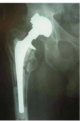
Total hip replacement (THR) is one of the most common and effective orthopaedic procedures performed both in the UK and worldwide, with the purpose of dramatically improving quality of life of patients suffering from debilitating hip disorders, such as osteoarthritis, rheumatoid arthritis and avascular necrosis. This procedure can bring almost immediate relief to the unremitting pain due to which the functional capacity of the lower limb has been greatly decreased. Especially to those patients with an end stage degenerative joint disease, THR is often the final attempt that the surgeons can resort to in terms of pain relief and increasing mobility. The first tentative steps toward restoration of function and alleviation of pain for patients with an arthritic hip involved many researchers and ideas, but a significant contribution to the routine success of today was undoubtedly the concept of the low-friction arthroplasty proposed by Sir John Charnley (1911– 1982) (Wroblewski et al. 2005). Since its introduction as a pioneering method in the 1960s, the basic structure of THR has remained unchanged, involving replacing the affected articulating hip joint with the use of a femoral component, which consists of a femoral stem with a femoral head on the neck, and a shell and liner system that acts as an acetabular cup, figure 1.1.
Figure 1.1: (a) Osteoarthritis at the hip (b) Total hip replacement with a metal prosthesis
There are primarily two fixation methods to secure the femoral stem into position in the femoral cavity, relying on either an uncemented method which depends on bone ingrowth into a porous or hydroxyapatite (HA) coating on the stem surface, or more common a cemented method which utilises acrylic bone cement for fixation. Bone cement functions as an intermediary agent between the prosthesis and the bone, to mechanically stabilise the femoral stem and to effectively transfer physiological loading from the prosthesis to the bone, figure 1.2. The acetabular cup is held into place in the same way as the femoral stem, either using an uncemented or a cemented technique. In the uncemented variety, the acetabular cup is simply stabilised by the tightness of the fit or with screws, whereas in the cemented variety, bone cement is used to fix the acetabular cup to the bone. The choice of uncemented versus cemented method remains highly personal and varies noticeably from one country to another. Even within countries, individual surgeons and research centres also
Femur Osteophytes Arthritic
hip joint
Arthritic femoral head
(a) (b) Acetabular
cup
have different criteria for selecting the type of fixation method. Across Europe, national variations range from 91% cemented THR in the UK to 10% in Austria (Wirz et al. 2005). However, the Hybrid THR, i.e. the combination of a cemented femoral stem with an uncemented acetabular cup, has nowadays become more and more popular for a large number of orthopaedic surgeons to treat the patients, especially those older than 50–60 years. The rationale for the hybrid THR is based on the experience that with the assistance of “modern cementing techniques”, the results on the stem side could be greatly improved, whereas on the acetabular side, clinical results with uncemented cup designs are more promising. The present research mainly concentrates on cemented THR regarding the fixation of the femoral stem.
Figure 1.2: (a) Uncemented total hip replacement (b) Cemented total hip replacement
1.1.2 Failure of total hip replacement
With a progressively increasing prevalence of THR performed in younger and more active people coupled with a longer life expectancy, it is hoped that hip prosthesis will function well for at least 15–20 years. Although the clinical success of THR has been well documented, especially with the improvement in implant design and the use of “modern cementing techniques”, revision does occur and it is required when one or more components fail. It is reported that up to 10% of the 65,000 operations carried out in the UK in 2007 are to revise those prostheses which have failed prematurely (National Joint Registry, 4th annual report, 2007). In comparison with the primary arthroplasty, revision is not only exposed to a considerably higher cost, but also associated with a decisively lower longevity and a higher rate of complication and morbidity. Consequently, great efforts have been made to investigate the scenario behind failure of THR. Nowadays, it has been generally accepted that this is mainly attributed to aseptic loosening, which dominates mechanical malfunctioning of the total joint system. Aseptic loosening of the hip prosthesis, usually with the symptom of a radiolucent line wider than 2mm around the prosthesis, has been identified as the predominant long term complication. It can occur in the absence of clinical or microbiological evidence of infection, and it is influenced by many factors such as periprosthetic bone resorption, poor initial fixation or alignment (Sutherland et al. 1982, Malchau et al. 1993, Johnsson et al. 1994, Mohler et al. 1995). Consequently, in spite of the long history of THR and the enormous
Acetabular cup Pelvic bone
Femoral stem
Femur
(a)
Acetabular cup
Femoral head
Femoral stem
Bone cement
This indicates that a deep insight into the etiology of aseptic loosening of THR should be gained and this would require much more fortitude and endeavour in research.
Notwithstanding, it has been shown from autopsy retrieved hip prosthesis that, with regard to cemented THR, periprosthetic bone resorption acts as the primary reason for aseptic loosening, associated with debonding at the femoral stem–bone cement interface (Jasty et al. 1991, Mjoberg 1997, Maloney et al. 2002). Bone resorption can be mainly attributed to an immune system response to particulate debris generated by wear of the hip prosthesis, and also to stress shielding because of changed loading conditions at the bone stock after implantation of the hip prosthesis. As the particles are liberated from the implant, stimulated macrophages attempt to clear them, resulting in an inflammatory reaction. This leads to the production of foreign body giant cells that release chemical mediators, such as prostaglandin E2, cytokines interleukin–1 and interleukin–6.
[image:19.595.228.368.294.504.2]These chemical mediators activate osteoblasts which will absorb bone from around the prosthesis, figure 1.3.
Figure 1.3: Typical periprosthetic bone resorption
1.1.3 The stem–cement interface
Previously, wear between the femoral head and the acetabular cup has been regarded as the primary source responsible for the generation of particulate debris as this interface is designed to allow for movement and to offer the patients flexibility. Recently, however, great progress has been made in reducing wear at this articulating interface with the advent of cross-linked ultra high molecular weight polyethylene (UHMWPE) (Wroblewski et al. 1996) and the renaissance of hard-on-hard bearing systems, e.g. metal-on-metal and ceramic-on-ceramic artificial hip joints (Firkins et al. 2001, Hatton et al. 2002).
stem–cement interface is showing an increasing significance in the overall wear of cemented THR. However, in spite of its potential importance, such wear has only received relatively little concern and its contribution to failure of cemented THR has been greatly overlooked. Previous studies have indicated that mechanical debonding at the stem–cement interface may be inevitable for almost all stem designs and this can result in subsidence of the femoral stem within the cement mantle (Karrholm et al. 2000). It is further suggested that, under cyclical physiological loading in vivo, the typical low-amplitude oscillatory micromotion at the stem–cement interface can lead to subsequent generation of fretting wear at this interface. Although fretting wear has been clinically detected on polished femoral stems, in vitro simulation to reproduce it has seldom been attempted and even then with only limited success. Additionally, it is demonstrated that wear mechanism at the stem–cement interface is mainly determined by femoral stem surface finish, with differing wear characteristics and severity of damage to bone cement in spite of similar wear locations on the femoral stem (Howell et al. 1999), but other factors such as stem geometry and bone cement brand may also influence the corresponding wear at this interface. Furthermore, the initiation and propagation process of this wear has never been established across previously published literature, and accordingly research needs to be undertaken to address these issues.
1.2Project aims and objectives
1.2.1 Aims
The overall aims of this current study are to give a better understanding of the characteristics of the stem–cement interface, to successfully and consistently reproduce fretting wear through in vitro wear simulations and to ascertain the influence of the potential contributory factors on the generation of fretting wear and on the wear mechanism. In addition, a model is to be developed to give a more detailed description of fretting wear generated on the stem surface. As a consequence, the work consists of a number of experimental studies and theoretical analysis.
1.2.2 Objectives
The specific objectives are given below in detail to fulfil the above aims, these include:
¾ To investigate the static bond strength of the stem–cement interface utilising polished femoral stems and several commercially available bone cements, with the purpose of validating that debonding at the stem–cement interface is commonplace.
¾ To study the influence of stem surface finish on the static bond strength of the stem–cement interface, using Simplex P bone cement and femoral stems with different surface finishes. ¾ To design a test fixture connected with an Instron test machine and to establish a test regime
to enable in vitro wear simulation of the hip prosthesis.
¾ To successfully and consistently reproduce fretting wear through development of in vitro wear simulations, using polished Exeter femoral stems and Simplex P bone cement.
¾ To develop an effective method to investigate the relative micromotion at the stem–cement interface during the in vitro wear simulation.
the initiation site and the locations of fretting wear, development of surface topography of the fretting zones, and generation of fretting debris, etc.
Chapter 2 Total hip replacement
2.1 Chapter summary
In the five decades since Sir John Charnley first advanced his revolutionary concept of a totally artificial hip joint consisting of a metal-on-plastic articulation, literally millions of people have had their lives dramatically and remarkably improved by this innovation. Equally to improve the basic design, many researchers have poured various ideas, efforts, and experience into this area. Understandings have developed significantly and new insights now abound to augment Charnley’s original design. It is considered essential to review the state of art of THR in order to make it clear where we are before carrying out any further research. The overall aim of this chapter is to obtain a general background of THR and to summarise the critical issues that need to be addressed through a comprehensive literature review, specifically concentrating on the characteristics at the stem–cement interface of cemented THR.
Firstly a fundamental knowledge of the loading regime of the hip joint is given, which is regarded as the basis that the configuration of in vitro wear simulation depends upon. The chapter then describes in detail two stem fixation methodologies based on two different principles. These two methods overwhelmingly predominate in modern THR procedure. As the cemented method is the one that this project is interested in, the characteristics of its two main components, i.e. metal femoral stem and acrylic bone cement, are further expatiated. Later in the chapter, the two primary reasons resulting in aseptic loosening of THR are outlined, these are summarised as wear debris induced bone resorption and stress shielding. Finally, the recognition and evaluation of femoral stem wear as a consequence of the fretting process at the stem–cement interface are introduced chronologically, and the initial attempts to reproduce fretting wear on the femoral stem through in vitro simulations are discussed.
2.2 The loading regime of the hip joint
2.2.1 Anatomy of the hip
femoral head and the acetabulum contact directly against each other. Consequently, an age-related degradation is predicted to occur to most people in the late stage with varying severity.
Figure 2.1: The structure of a natural hip
Generally speaking, the main functions of the hip joint are to transmit physiological loading from the human body to the thigh bone and then to the lower limb, and also to allow for mobility of the leg in space. It has three degrees of freedom, all of which are rolling, figure 2.2 and table 2.1.
Figure 2.2: Definition of degree of freedom of hip motions
Table 2.1: The three degrees of freedom of the hip joint
Hip movement Explanation Plane of motion Axis of rotation Range
Abduction/adduction Spin with inferior/superior glide of the femoral head inside the acetabulum
Frontal plane A sagittal axis passing through the centre of the femoral head
Up to 90˚
Internal/external
Spin with inward/outward glide of the femoral head
inside the acetabulum Transverse plane
A vertical axis passing through the centre of
the femoral head Up to 90˚
Flexion/extension Spin with posterior/anterior glide of the femoral head inside the acetabulum
Sagittal plane A frontal axis passing through the centre of the femoral head
Up to 145˚ and 30˚ respectively
Ligament and joint capsule
Articular cartilage Synovial fluid
Ligament and joint capsule
Femur Synovial membrane
Adduction
Abduction Internal External
Due to the little restriction to rotation, the hip joint is considered to be inherently unstable. It would finally lead to a complete loss of function of the lower limb if often subjected to excessive loading. A fundamental knowledge of the variation in these three degrees of freedom is essential in replicating normal human activities, in evaluating curative effects of THR and also in designing a hip simulator. For example, the hip joint is flexed 30˚, adducted 3˚ and internally rotated 5˚ at heel strike of a gait cycle, and extended 15˚, adducted 3˚ and internally rotated 5˚ at toe off.
2.2.2 Hip joint force
The success of THR largely depends on its ability to transmit physiological loading of the human body without failure, therefore an insight into the forces acting on the hip joint is required. It is well known that the hip joint force applied on the femoral head is considerably greater than the human body weight (BW) during walking, and it is even higher in other situations such as stair climbing, running and stumbling (Davy et al. 1988).
To date there have been a great deal of investigations performed concerning hip joint force. The first study of in vivo measurement of the force is considered to be the one carried out by Rydell in 1966. In that study he employed a metal prosthesis instrumented with strain gauges and collected data through subcutaneous leads. The peak force value was found to be about 3.3BW during walking for dynamic measurements. Another area of early research on the forces transmitted by hip joint in the human body completed by Paul in 1967 resulted in a curve that is still regarded as one of the standard loading configurations for modern hip simulators. He obtained a peak hip force value of around 3.9BW at a relatively low velocity in one walking cycle, figure 2.3. English and Kilvington in1979 recorded similar values employing a telemetry system implanted in a hip prosthesis. More recently, Bergmann et al. (1993) measured in vivo hip forces in two patients, using a telemetering total hip prosthesis. They recorded that the peak force value during walking ranged between 2.8BW and 4.8BW, and it was as high as 5.5BW when jogging and 8.7BW when stumbling. This data is summarised in table 2.2.
Table 2.2: Typical studies on hip joint forces during different human normal activities
Authors Activities Resultant forces
Rydell (1966) Walking 3.3BW Paul (1967) Walking 3.9BW English and
Kilvington (1979) Walking One-legged stance 2.56BW 3.59BW
Bergmann et al (1993)
Walking Jogging Stumbling
Between 2.8BW and 4.8BW 5.5BW
8.7BW
Although there are some variations among these studies, they all have confirmed that the hip joint is a weight bearing interface that experiences high physiological loading during human normal activities. As a result, there is no doubt that a gradual degradation in the function of the hip joint will occur if it is always being overworked. It follows that, if the articular cartilage is worn, an implicated hip disorder, commonly osteoarthritis, would be likely to be accelerated, leading to extensive impairment to people’s quality of life. In such a case, a THR operation may have to be subsequently carried out to reconstruct function of the hip joint and to relieve the pain. This procedure is considered to be the most effective treatment in comparison with other methods, e.g. anti-inflammatory medications, as it allows the patients who have struggled with the simple action of walking once again to participate in most ordinary daily activities following a relatively short period of rehabilitation.
2.3 Uncemented and cemented total hip replacement
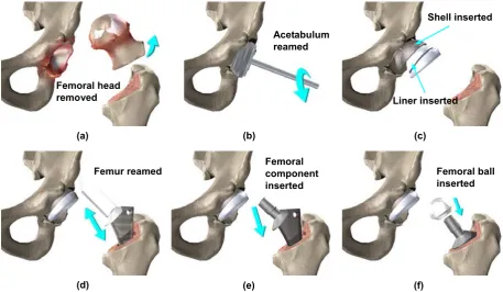
THR is deemed as one of the major advances in medicine of the 20th century and it is typically required when osteoarthritis results in severe discomfort and disability to the patients. Basically, a THR procedure involves several steps, including removal of the affected femoral head, reaming of the acetabulum and subsequent insertion of a metal shell and an acetabular cup, reaming of the femur and securing of a femoral stem with a ball on the neck into the femoral cavity, figure 2.4.
2.3.1 Uncemented total hip replacement
Figure 2.4: Typical procedures of total hip replacement
Sintered porous-coated and plasma-sprayed HA coated implants have now been comprehensively used to allow for mechanical interlock and fixation of the stem to the surrounding bone, especially the osteoconductive HA coated implant which was initially introduced by Geesink et al. in 1987. The early prognosis of uncemented THR has been reported as good, which promotes direct bone apposition. The long term clinical success, however, is of major concern. The potential problems involved in these implants such as delamination or fragmentation of the coatings and subsequent exposition of metal beneath may become predominant during its in vivo service (Porter et al. 2004), releasing particulate debris and invoking a foreign body host response. The particulate debris would also migrate into the joint articulation regions where they can act as third-body particles causing higher wear rates of the bearing surfaces and further consequences from the greater volumes of liberated wear debris. Additionally, subsidence of the stem relative to the bone is considered to be extremely detrimental to bone ingrowth, and it is indicated that bone ingrowth will not occur if the initial micromotion is excessive (Pilliar et al. 1981). In summary, uncemented hip prostheses offer the advantage of fixation by direct bone-to-implant osseointegration, therefore avoiding the use of a synthetic intermediary material with limited mechanical strength, such as acrylic bone cement. As a consequence, uncemented THR is preferably performed for the younger patients with good bone quality. However, severe thigh pain or discomfort emerges as a long term challenge and sequela for uncemented THR, and successful osseointegration depends on several multifactorial conditions being satisfied, including the need for limited early loading which will hopefully lead to minimal relative movement at the stem–bone interface.
2.3.2 Cemented total hip replacement
The rationale behind the cemented method is to employ acrylic bone cement as a medium for fixation of the stem. Given the demographics in many countries, it seems in all probability that
Femoral head removed
(a)
Acetabulum reamed
(b)
Liner inserted Shell inserted
(c)
Femoral ball inserted
(f) Femoral
component inserted
(e) Femur reamed
even with the progress in uncemented fixation and tissue engineering (Smith 2005). Therefore, there is great requirement to gain a deep insight into this biomaterial, especially its application in the area of THR. Actually, cemented THR has been accepted as the more popular mode for stem fixation throughout Europe and it is in part why this current research focuses on cemented THR. Bone cement was originally designed for use in dentistry, and it was Sir John Charnley (1960) who introduced it to orthopaedic surgery. This advance was not simply the utilisation of bone cement but rather a conscious recognition of its ability to completely fill the medullary canal and to adapt to the bone interface, thereby anchoring the hip prosthesis. It was a brand new technique and provided the basis for the development of the Charnley low friction arthroplasty over the following decades.
Bone cement has now been used in cemented THR for more than 40 years. As a grouting material, bone cement allows for almost immediate stabilisation of the femoral stem and smooth transfer of physiological loading from the metal prosthesis to the bone. During the surgical procedure, it is introduced into the femoral cavity prior to insertion of the femoral stem. Upon polymerisation, the bone cement cures into a solid dough state in approximately 15 minutes, which can then steadily hold the stem in position. This procedure is preferably recommended for older patients over age 60, or younger patients with poor bone quality and density who cannot tolerate a long period of rehabilitation. Therefore, these individuals benefit greatly from the relatively short healing time, usually from one to two weeks. The hospital cost of implanting a cemented femoral stem is commonly more than that of implanting an uncemented femoral stem, when adding together the cost of additional operating room time and anaesthesia time, and the cost of stem, cement and other accessories (Barrack et al. 1996). Although both short term and long term survivorship of cemented THR has been well documented in part due to the improvement in “modern cementing techniques”, aseptic loosening is generally regarded as a major threat to its durability (Raut et al. 1995, Herberts and Malchau 2000), with sometimes an unacceptably high rate of hip implant loosening reported in some centres through 1960s and 1970s. These unsatisfactory results, associated with the intrinsic limitations of acrylic bone cement in mechanical properties, partially resulted in research initiatives intending to develop alternative methods for reliably and durably securing hip prosthesis in bone, i.e. uncemented THR. Over the years, uncemented and cemented methods have proved to be much effective for THR therapy, with the selection of one or the other approach being favored, depending on specific situations.
2.4 Metal femoral stem
2.4.1 General introduction
Figure 2.5: Different designs of femoral implants
These stems no doubt offer more flexibility in terms of geometry as well as cost, but they to a certain degree make the optimal choice for the patients very difficult considering that a long term follow up is required to assess the performance of a new stem design. What is worse, some of the new designs met with an extremely unsatisfied survivorship since being used, i.e. the 3M Capital hip system (3M Health Care Ltd., Loughborough, UK). These stems, available in both monoblock and modular forms, were introduced to the UK market in 1991, and shortly adverse reviews reported that between 19% and 21% of patients either had undergone revision surgery or were identified as being in need of revision at less than five years (Medical Devices Agency, hazard notice, 1998). Therefore, a balance needs to be struck between the demand for long term clinical data before a stem is released to market and also the demand for continued development in order to improve longevity of THR. Nowadays, Charnley, Exeter, Stanmore, and Müller stems are generally regarded to be “benchmarks” across all stem designs and the long term durability of these stems has been well evaluated (Shen 1998).
more potential wear sites that have been introduced at the Morse taper. However, the benefits given by the modular stem design appears to far outweigh this potential problem, especially with the use of ceramic as a material for the femoral head to further reduce wear.
Figure 2.6: (a) Example of a modular femoral stem design—Exeter (b) Example of a monoblock femoral stem design—Charnley
2.4.2 Design properties
2.4.2.1 Stem material
There are many variables when designing a femoral stem, including material, geometry, surface finish, etc. With reference to material selection, biocompatibility and optimal mechanical and tribological properties are of prominent significance, taking into consideration the aggressive physiological environment in the human body as well as the complicated loading regime on the femoral stem in vivo (Semlitsch and Willert 1980). The material must be able to withstand physiological loading for the duration of day-to-day utilisation by an active individual. As most materials used in biomedical engineering are much stronger than the requirements for yielding and fatigue, the strength of the material is no longer a critical issue. There is, however, another very important design constraint for material selection, i.e. stress shielding. Stress shielding is the reduction in bone density due to much of the load being carried by a much stiffer implant, which results in a huge stress gradient between the cancellous bone and the lower region of the femur. This is associated with resultant pain and discomfort for the patients. As a consequence, it is ideal to choose those materials with similar strength, stiffness, density and other mechanical properties as the bone to reduce the stress shielding effect. Nowadays, stainless steel, cobalt chrome alloys, and titanium alloys are the three most commonly used materials primarily attributed to their biocompatibility and excellent mechanical and tribological properties. Unfortunately, all of these materials possess yield strength and stiffness much higher than that of bone. Femoral stems made of titanium alloys have gradually received a reputation for failure earlier than the cobalt chrome and stainless steel designs because titanium is susceptible to crevice corrosion, which is driven by the generation of a gap between the stem and the cement, and also between the head and the taper.
(b) (a)
Therefore, there are certain concerns when manufacturing a femoral stem utilising titanium alloy, and titanium articulating surfaces are no longer recommended for clinical use.
2.4.2.2 Stem geometry
[image:30.595.173.427.492.697.2]In addition, stem geometry is also considered to be very important because it may have a direct effect on the in vivo behaviour and consequent failure mechanism of THR. Certain unsuccessful stems such as the 3M Capital hip have been removed from the market as a very poor short term survival rate was obtained, and this has been suggested to be highly design-related. The optimal geometry of a stem should transfer axial as well as torsional load through the bone cement and then to the bone without creating destructive peak stresses and without excessive micromotion. Generally speaking, stem geometry design involves the overall shape (symmetrical or anatomical), the cross-section (oval or square), the presence or absence of a collar and a flange, the shape of the stem tip, and the length of the stem. Also, it includes whether the edges are rounded to a greater or lesser degree, and whether the stem is double taper design (e.g. Exeter stem) or triple taper design (e.g. C Stem, figure 2.7). Charnley, Exeter, and Müller stems are all symmetrical designs, with excellent clinical track records. Anatomical stem designs such as Lubinus SP2 can generate different strains within the cement mantle because of their specific shape, which allows for better centralisation of the stem and more even thickness of the cement mantle. The cross-sectional shape influences the distribution of cement within the femoral canal, the rotational stability of the implant, and the stress distribution within the cement mantle. Stems with a square cross-section offer more rotational stability than stems with an oval cross-section. However, the sharp edges create peak stresses in the cement, potentially leading to micro-cracks (Scheerlinck and Casteleyn 2006). Nowadays, although there are still no published results for some of the hip implants on the market, the number of THR designs that are available to surgeons is rapidly increasing. Therefore, an effective early clinical assessment of the performance of a new femoral stem design is greatly necessary.
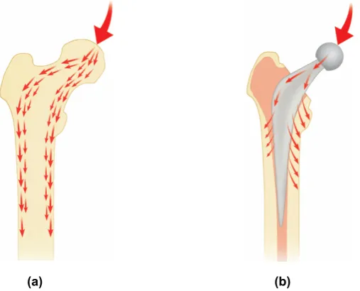
Figure 2.7: Load transfer patterns (a) Within the natural femur (b) Around the C stem
2.4.2.3 Stem surface finish
stems. There are currently no standards relating to this and therefore its influence on the reliability and longevity of cemented THR has been debated for a long time. The focus of controversy concentrates mainly on whether matt femoral stems can achieve permanent fixation during long term in vivo service. Undoubtedly, the stem surface texture has a direct effect on the interaction with bone cement, which as a consequence functions as a significant factor in influencing the bond strength at the stem–cement interface. From a mechanical perspective, matt stems can form much greater bond strength at this interface than polished stems, mainly owing to the enhanced bone cement attachment. Therefore, a matt femoral stem with a collar and a flange is termed as “shape closed design” which tends to obtain its stability through mechanical interlock between the stem and the cement. By contrast, a polished femoral stem incorporated with a collarless design is termed as “force closed design” which depends on mechanical taper locking of the stem within the cement mantle to accomplish self-tightening (Huiskes et al. 1998). This is taken to be the rationale behind the great success of the Exeter polished femoral stem, which has been changed back from the matt surface finish design based on the fact that an inferior clinical outcome was obtained for the matt stems. Originally, the Exeter femoral stems were highly polished before 1976. There was no particular reason for this except that it was “the fashion” for many femoral components of that era. Later from 1976 to 1985, the Exeter femoral stem had a matt surface as it is quite expensive to polish a stem. Whilst the occurrence of stem fracture with the matt-surfaced stems was virtually abolished, there gradually emerged the paradoxical finding of a great increase in the incidence of focal femoral lysis and aseptic loosening (Anthony et al. 1990), which directly resulted in the re-introduction of the polished surface at the beginning of 1986. Basically, matt femoral stems are prone to generate more debris and cause severe damage to the cement mantle once debonding at the stem–cement interface occurs. This is considered to be the primary disadvantage involved in matt surface finish design. Although it is still an area of debate for the optimal stem surface finish, more and more documents are being published to support for the use of polished femoral stems (Howie et al. 1998) as in some cases matt stems have shown to fail earlier than polished stems of the same type, such as the Exeter stem and the Iowa stem. Matt stems may preferably need a thick, continuous cement mantle of good quality with a strong cement–bone interface to function well. One would expect that it should not be a problem to distill the optimal design parameters as there has been to date a clinical database representing over two decades survival data of cemented THR. However, it is such a complex matter that from a clinical point of view conclusive evidence for the optimal implant design remains elusive. One design feature would have a negative effect for a particular design, whereas it has none or even a beneficial effect for another prosthetic design. Therefore, it definitely is a combination of inferior design features that result in a bad hip implant. In this respect, it has been suggested that one must consider a certain design philosophy, e.g. “shape closed design” or “force closed design”, rather than in individual design features. When a design philosophy is adopted, all design features can be chosen to match the particular philosophy and to optimise the clinical performance (Verdonschot 2005). Failure to do this would result in arbitrary mixing of design features and potentially a painful lesson in history.
2.5 Acrylic bone cement
Acrylic bone cement was initially used in dental surgery, and then in the 1960s Sir John Charnley at Wrightington Hospital pioneered its application as a grouting material to stabilise hip prosthesis in orthopaedic surgery, which is nowadays one of the most frequently performed orthopaedic procedures across the world. In spite of more than 45 years of usage, its basic composition has remained largely unchanged, with a fine polymer powder and a vial of monomer liquid as the general components. The powder consists of pre-polymerised polymethylmethacrylate (PMMA) or PMMA-based copolymers, benzoylperoxide (BPO), and a radiopaque agent, commonly barium sulphate (BaSO4) or zirconium (ZrO2). BPO behaves as an initiator for the polymerisation reaction;
BaSO4 and ZrO2 are radiopacifiers to aid in radiological assessment of cemented THR. The liquid
is composed of methylmethacrylate (MMA) monomer, N, N dimethyl para toluidine (DMPT), and hydroquinone (HQ). From a chemical point of view, MMA monomer is an ester of methacrylic acid with a polymerisable double bond, and it is a clear, colourless, flammable liquid with intense odor; DMPT is a tertiary aromatic amine that acts as an activator for the polymerisation reaction; HQ is used to prevent spontaneous polymerisation of the monomer due to exposure to heat or light during storage to guarantee a sufficient shelf life. All the bone cements on the market have similar liquid compositions but considerably different powder composition. Upon mixing the powder and the liquid, BPO and DMPT participate in a redox reaction or a so called “initiation reaction”, producing free radicals which initiate additional polymerisation of MMA monomer by adding to the polymerisable double bond of the monomer molecule. Because of the high number of radicals generated, many rapidly growing polymer chains are formed, and there is a fast conversion of MMA to PMMA. If two growing polymer chains meet, they are terminated by combining both, resulting in an unreactive polymer molecule, figure 2.8. During the polymerisation process, the admixture gradually experiences a transition from liquid to solid, and then it is transferred to the reamed femoral cavity which is ready for insertion of a femoral stem.
Figure 2.8: The formation of polymer chains (a) Radical for initiation of polymerisation and MMA monomer (b) Growing polymer chain with reactive site at the end (c) Final polymer molecule
There are currently numerous brands of acrylic bone cement commercially available on the market. According to the viscosity disparities when they are introduced to the femoral bone cavity, bone cements can be classified into three categorisations: low viscosity (e.g. Cemfix 3, Coriplast 3), medium viscosity (e.g. Simplex P, CMW 3) and high viscosity (e.g. Palacos R, CMW1). Low viscosity bone cements have a long lasting wetting phase and the material usually remains sticky for three minutes or longer. High viscosity bone cements have a relatively short wetting phase and
+
MMA MMAMMA MMA MMA MMA
Radical Radical MMA MMA MMA MMA MMA MMA
(a)
(b) MMA MMA
MMA MMA MMA MMA
+
MMA MMA MMA MMA MMA MMAMMA MMA
MMA MMA MMA MMA MMA MMA MMA MMA MMA MMA
mainly by the chemical composition and the powder to liquid ratio. However, there is one method to modify the viscosity without changing other characteristics of the cement, i.e. pre-chilling the cement. As pre-chilling the cement can slow down the polymerisation by reducing the maximum temperature during the process of polymerisation, the viscosity is therefore to some extent reduced. Nowadays, there are five most commonly used bone cements, which are summarised in table 2.3.
Table 2.3: The five most commonly used bone cements
Bone cement brands Suppliers
Simplex P Howmedica International Inc., Limerick, Ireland Palacos R Biomet Merck Ltd., Bridgend, UK
CMW DePuy International Ltd., Leeds, UK Zimmer Zimmer Inc., Indiana, USA
Sulfix Sulzer Brothers Ltd., Winterthur, Switzerland
2.5.2 Mechanical and physical properties
Although these commercially available bone cements vary slightly in composition, they possess significantly different mechanical properties. Bone cements endure considerable stresses in vivo, therefore sufficient mechanical strength is one of the most important demands to achieve stable fixation and to guarantee long term stability of the hip implant. There are two different measuring principles to determine mechanical properties of bone cement, one applying static stresses and the other applying dynamic stresses. Static tests are destructive tests with a uniaxial single loading, increasing until failure, whereas dynamic tests involve a cyclical loading. In general, acrylic bone cement displays high strength in compression, whilst its brittle characteristic is noticeable under tension and bending. Common bone cements on the market display 75–105MPa for compressive strength, 65–75MPa for bending strength, 50–60MPa for tensile strength. According to the BS ISO standard 5833, the vast majority of commercial antibiotic and plain bone cements are compliant with these requirements. Additionally, it is indicated that fatigue failure of bone cement will occur at a load much lower than the predicted ultimate strength, and bone cement fractures and cracks have been observed from hip retrieval studies and they are suggested to be one potential reason to promote aseptic loosening of the femoral stem (Eliades et al. 2003), figure 2.9.
Consequently, great efforts have been made in order to improve the mechanical properties of bone cement and also the mixing technologies. One method that has been comprehensively attempted is the so called “modern cementing techniques”. Table 2.4 shows the typical characteristics of three generations of cementing techniques. Bone cement was originally mixed in a bowl and manually finger-packed into a reamed and irrigated bone cavity. This method would expose the surgeons to noxious fumes released by the MMA monomer. The second generation cementing technique was developed to enhance the interlock between the cement and the surrounding cancellous bone. This as a consequence resulted in a greater scrutiny of the cement itself and the stem–cement interface, which is the main purpose of the third generation cementing technique. It has been indicated that a better reliability and survivorship of cemented THR is achieved through the use of “modern cementing techniques”, probably in part due to the reduction of porosity of the cement mantle (Mulroy and Harris 1990). Porosity is considered to be a major cause of reduced fatigue life of bone cement. The micropores generated and sometimes even the macropores can be introduced through air initially surrounding the powder, and air trapped in the cement during mixing and during transfer from the mixing container to the application device. Those pores are often cited as stress risers to initiate and propagate cracks and fractures within bone cement mantle.
Table 2.4: Typical characteristics of three generations of cementing techniques
First generation (1960s) Second generation (1970s) Third generation (late 1980s)
Finger packing Hand mixing Vacuum mixing Distal plugging Distal plugging
Pulsatile lavage cleaning Pulsatile lavage cleaning Syringe injection Centrifugation
Bulb syringe irrigation
Retrograde cement delivery with gun Centralisation and pressurisation
(Kuehn et al. 2005). It has been proposed that the creep behaviour of acrylic bone cement may contribute to loosening of cemented THR, allowing for expansion of bone cement mantle and subsequent prosthetic subsidence although it was reported to be small (Verdonschot and Huiskes 1997a). On the other hand, creep of bone cement could relax cement stresses and creates a m