University of Huddersfield Repository
Assairi, Bandar and Holmes, Violeta
iShoes for blind and visually impaired people
Original Citation
Assairi, Bandar and Holmes, Violeta (2013) iShoes for blind and visually impaired people. In:
Proceedings First International Conference on Technology for Helping People with Special Needs.
ICHTP 2013 . AlImam Mohammad Ibn Saud Islamic University, Riyadh, Kingdom of Saudi
Arabia, pp. 1015.
This version is available at http://eprints.hud.ac.uk/id/eprint/16888/
The University Repository is a digital collection of the research output of the
University, available on Open Access. Copyright and Moral Rights for the items
on this site are retained by the individual author and/or other copyright owners.
Users may access full items free of charge; copies of full text items generally
can be reproduced, displayed or performed and given to third parties in any
format or medium for personal research or study, educational or notforprofit
purposes without prior permission or charge, provided:
•
The authors, title and full bibliographic details is credited in any copy;
•
A hyperlink and/or URL is included for the original metadata page; and
•
The content is not changed in any way.
For more information, including our policy and submission procedure, please
contact the Repository Team at: E.mailbox@hud.ac.uk.
iShoes for blind and visually impaired people
Bandar Assairi
MSc Embedded Systems Engineering
School of Electronic and electric EngineeringThe University of Leeds Leeds, United Kingdom el12bsaa@leeds.ac.uk
Dr Violeta Holmes
Computing and Engineering The University of Huddersfield Huddersfield, United Kingdomv.holmes@hud.ac.uk
Abstract— This paper presents the development of an iShoes system for blind and visually impaired people. The iShoes system utilizes a microcontroller with sound output interfaced with ultrasonic sensors. The prototype system is designed to be specifically mounted on/in the shoes to aid navigation in urban routes. The ultrasonic transducers determine the range from an obstacle and then play an audio message to reflect the distance from the target. This system will assist blind and visually impaired people in navigating a path through an unfamiliar environment.
Keywords—Ultrasonic guidance system; ultrasonic sensors; blind, visually impaired; navigation
I
INTRODUCTION
For those who are fortunate enough to have good eyesight, it is hard to comprehend how difficult it is to live without being able to see. Visual impairment and blindness is caused by a number of factors which include; disease, malnutrition, and hereditary factors [1]. Blind or visually impaired people make use of blind cane to aid them in walking by allowing them to sense the obstacles in front of them [2].
There are a number of projects investigating technologies to assist the blind. Calder et al. developed an assistive technology interface especially for the blind. When worn by the visually impaired or blind user, it warns the user of obstacles ahead by using an ultrasonic pulse-echo method to determine the range of the object distance [3]. Noor et a.l studied a bus detection device for the blind using RFID application. The blind used auditory touched clues like a walking stick or white cane to determine where to move to. This system is limited as it can only help the blind at pedestrian crossing [4].
Our aim was to build an obstacle detection embedded system for a visually impaired or blind person to detect objects in the direction of movement. This system would send warning by sounding an audible message to ‘stop’, ‘move backward’ or ‘turn left’ or ‘right’ to proceed by avoiding the obstacles. In future it will also incorporate a GPS system to allow inputting the direction to the destination and then guiding the blind person to the destination.
The main motivation for carrying out this project is to design and implement a system which will be a much needed aid to the blind or partially sighted person. By designing and implementing such a system, taking into consideration the
needs and requirements of a blind person, this project will contribute to solving a major problem faced by blind people, ease their life and make them less dependent on others. As a result of our investigation we have designed and built a working prototype system on a PCB containing two ultrasonic sensors for each shoe to detect obstacles in the path of movement. This was achieved by interfacing the sensors to microcontrollers to calculate the distance detected by the two sensors and to sound messages to take necessary actions. The prototype models, a pair of iShoes, are interfaced in a standalone system for testing and validation purposes in real time situations.
II iShoes system design
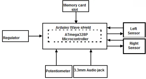
The whole system is designed around an ATmega328 microcontroller Board. The ATMEGA328 microcontroller is the core and the most important component of the iShoes tracking manager. The main code is stored onto the chip’s programme memory. It can collect data from an external memory where different sound tracks are kept, such as audio file for “stop”. The block diagram showing the system functionality is shown in figure 1:
Figure 1: Block diagram of ultrasonic navigation system
[image:2.595.320.566.474.607.2]current code and future development. Sensors S1 and S2 are utilized to sense obstacles and help generate correct instructions to guide blind to the desired place.
Once the sensors S1 and S2 receive sound from the microcontroller, if an obstacle is present in a line of movement, the sound gets reflected onto a detector. The detector receives ultrasound waves and gives a signal to the microcontroller unit. Based on a relative position of the obstacle in relation to left and right leg, the system will automatically play appropriate instructions. If the object is closer to the right leg, the instruction will be to “stop and turn left”; for left leg to “stop and turn right”; equidistant from both right and left leg to “stop and then choose a direction”. Both sensors detect the obstacles or objects whenever the user approaches the objects at the distances of 150 cm, 100 cm and 50 cm. If a distance from an object is from 150 cm to 100 cm, then the object is close to the set target/limit. If the distance is 100 cm to 50 cm the object is too close to the target; or 50 cm to 0 cm then the left and the right leg are very close to the object. These ranges of distances are used to deduce if the unit needs to issue a warning to turn either left or right.
III TECHNICAL DESCRIPTION
The system requires a regulator or power supply of 5Volt. The power supply is directly connected to the Arduino wave shield/component.
The Hardware components used for the system design are briefly described below:
3.1 Ultrasonic Sensor
[image:3.595.323.568.461.607.2]Ultrasonic range detection sensor requires 5V DC voltage. Throughout the circuit, maximum current supplied is 15 mill amperes. The frequency is around 40 HZ. The normal output ranges from 0-5 volts and if any obstacle is present then the output is high. The maximum sentry angle used is 15 degrees. The distance between the sentries is 2 cm to 500 cm. The accuracy is high - up to 3 cm. It triggers input signal for 10 micro seconds based on Transistor –Transistor logic impulse form. The echoed signal output is in the form of TTL PWL signal. The size form factor is 45mm * 20mm * 15mm [6].
Figure 2: Pin interface of Ultrasonic sensor [4] .
3.2 Voltage regulator
A 3.3V voltage regulator takes 5V supply from Arduino and converts it to 3.3V supply. Here the understanding of 3.3V voltage regulator is very easy. The conversion of 5V supply to
a 3.3V supply is needed because the SD/MMC cards can only work on a 3.3V supply. Otherwise if 5V supply is given to the card it will burn and cause failure of the entire board. MCP1700-330 is the voltage regulator, the current provided by this voltage regulator is 250mA and it consists of 4 capacitors. The capacitors are associated with the voltage regulator. To stabilize the 5V input C1 and C2 capacitors are used; C1 and C2 are the input capacitors. To stabilize the 3.3V output C3 and C4 capacitors are used where C3 and C4 are the output capacitors.
2.3 ATmega328 Microcontroller
[image:3.595.106.235.532.636.2]The ATmega328P is a microcontroller with 8-bit and high performance characteristics. The architecture is called RISC architecture. For fully static operation up to 16 MIPS throughout with 16 MHz on chip 2 cycle multiplier is used to execute maximum single clock cycle. It has about 131 powerful commands for 32 X 8 general purpose working registers. The memory segments are high endurance and non-volatile with 32K bytes of flash memory which is In-system self-programmable and 1Kbytes of EEPROM with 2K bytes of internal Static RAM (SRAM). For capturing and compare mode, the ATmega328P microcontroller has the peripheral characteristics of two 8-bit Timer/Counters with detached prescaler which compares the mode, and one 16-bit Timer/Counter with detached prescaler. Other functions of the ATmega328P include ADC noise reduction, Power save, Power down, Standby and extended standby are special features. Is has 23 programmable I/O lines combining both input and output packages and it ranges from operating voltage between 2.7V to 5.5V. The operating temperature range is in between -40 degree Centigrade to +125 degree for the automotive temperature [7]. The ATmega328P block diagram is shown in the Figure 3:
Figure 3: Atmega 328P Microcontroller [8]
3.3 Micro SDHC Card Series
system used in this SDHC cards is FAT32. The operating voltage is from 2.7V to 3.6V and the temperature ranges from -25 to 85˚C respectively. The durability of this card is 10,000 insertion and removal cycles. It supports speed class 6 specifications. This card supports the protection of copy for SD-Audio and Recorded media. The compatibly of this card is seamless with compliant digital audio devices (SDMI). The form factor for this card is 11mm x 15mm x 1mm. By using the mechanical wire protection switch the Micro SD adapter is designed.
3.4 Potentiometer
The potentiometer uses analogue control and splits the analog signal from 5Vpp down to 0Vpp. If the voltage changes logarithmically then the human ears can interpret it as when input is an audio file.
IV SOFTWARE DESCRIPTION
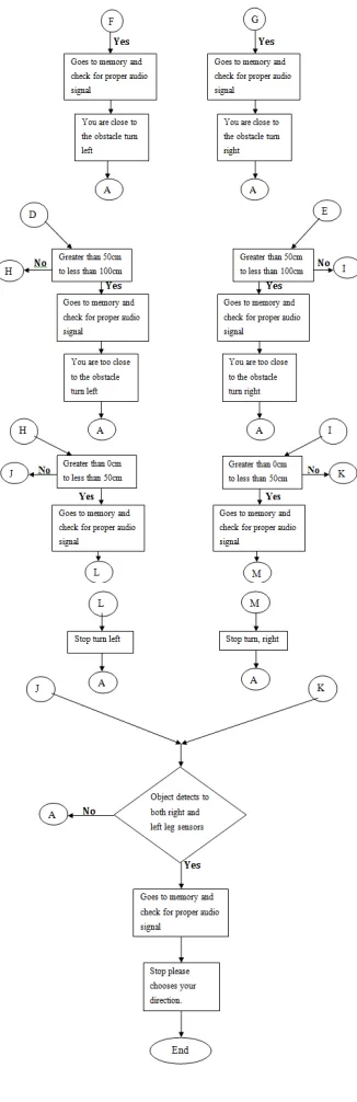
[image:4.595.353.532.405.767.2]The software for this system is implemented in Arduino Wave Shield using the Arduino Library. The Arduino library is an open resource based library which has useful functions used such as Pinmode(), DigialWrite() and DigitalRead(), to enhance the design of the system involved in this project. The EEPROM library provides varies functions such as read and write. These two functions are used to read and write to or from EEPROM memory of the microcontroller. Rule-based algorithm was design and implemented. The flowchart diagram that represents the system performance is shown in Figure 4.
1. Start.
2. Both right leg and left leg sensors are activated.
3. Sensors start sensing to detect the obstacles while sending echo signal as a transmitter signal and receiver receives the trigger signal.
4. If yes and any object detected, then the sensor sends interrupt to the microcontroller to check that the obstacle detects at right leg sensor or the left leg sensor.
5. If no then both sensors start sensing again. 6. If right leg sensor or the left leg sensor detects the object then immediately start measuring distance of the obstacle.
7. If the object is detected at the distance of greater than 100cm and less than 150cm then from the memory an audio signal is selected and played on the speaker or headphones by using the 3.3 audio jack.
8. If the object is detected at the distance of greater than 100cm and less than 150cm at the right leg sensor, it plays the audio signal ‘ you are close to the obstacle turn left ’ or if it left leg sensor detects the obstacle it plays the audio signal ‘you are close to the obstacle turn right’.
9. If the object is not detects in between the range of the 100cm to 150cm then it branches to greater than 50cm to less than 100cm automatically
checks for the proper audio signal and it plays it on the speaker or headphones by using the 3.3mm audio jack.
10. If the object is detected at the distance of greater than 50cm to less than 100cm at the right leg sensor, it plays the audio ‘ you are too close to the obstacle turn left ’ or if it left leg sensor detects the obstacle it plays the audio signal ‘you are too close to the obstacle turn right’.
11. If there was no object detected in between the ranges of the 50cm to 100cm then it finally checks for greater than 0cm to less than 50cm; if its
yes then it automatically goes to memory and selects the proper audio signal and plays it on the speaker or headphones by using 3.3mm audio jack.
12. If the object is detected at the distance of greater than 0cm to less than 50cm at the right leg sensor it plays the audio ‘ stop and turn left ’ or if it left leg sensor detects the obstacle it plays the audio signal ‘stop and turn right’.
13. If it is no in these three cases and the obstacle detected is equidistant from both right and left leg sensors, it selects from the memory proper audio signal to play on the speaker or headphones by using 3.3mm audio jack.
Figure 4: Flowchart of iShoes system design
The Arduino library functions, used in this design, are briefly outlined below.
4.1 Pinmode()
Whether it acts as an input or output the pinmode() controls the specified pin. The top parameters in this pinmode() are pins which are set in their respective modes. There is also a parameter - mode; two modes are provided: input and output.
4.2 DigitalWrite()
To write a HIGH or a LOW value to a digital pin digitalWrite() library is used. Pin voltage will be put to the analogous value: 5V for HIGH, 0V (ground) for LOW if the pin has been configured as an OUTPUT with pinMode(). Writing a HIGH value with digitalWrite()enables an internal 20K pull-up resistor when the pin is assigned as an INPUT and it will disable the pull-up if we write LOW. To light an LED dimly pull-up register is used, then LED can run but with small brightness. Setting the pin to an output with the pinMode() function is means of overcoming this shortcoming. The main parameters used in this digitalWrite() is pin number. And the value of that pin is LOW or HIGH [7].
4.3 DigitalRead()
This digitalRead() library is applied to read the value form certain digital pin, which can be LOW or HIGH. The top parameter utilized in this digitalRead () is the pin number of the pin which is to be read
.
5 TEST RESULTS
The sensor test results indicate that the pulse repetition time of the echo signal for the ultrasonic range detection is 3.05 seconds. Both sensor 1 and sensor 2 were tested successfully to detect the obstacles or objects in front of a blind person. For example, sensor 1 is attached in front of the left leg shoe, so sensor detects the object at 23 cm and gives instruction to a blind person to stop walking, and sensor 2 is attached in front of the right leg shoe, so sensor detects the object at 132 cm and passes the signal to a blind person that obstacles is very close so to take turn left. If sensor 2 detects an object at 78, then automatically signal indicates to a blind person that object is too close, so to stop walking and take turn right.
Figure 5 shows the output results for both sensors when tested in Arduino terminal.
[image:5.595.335.543.562.684.2]It is important to note that the results are saved on the Micro SDHC card and can easily be retrieved when needed. The maximum range of the sensors for the left and right shoe is 201cm. Audio files are activated as shown in the flowchart of the algorithm and are relayed to a blind person to turn right of left.
The system was thoroughly tested. Both ultrasonic sensors were tested to detect the presence of obstacles in front of the leg of a blind person. The testing showed in figure 5 that when sensor 1 senses an object 23 cm from it, it correctly and in a timely manner gives instruction to a blind person to stop walking. The right sensor, on detecting the distance of 132 cm from the object, also gave the signal to a blind person using audio message to turn left. These were some of the tests conducted to test the sensors and system performance. The other tests also proved that the ultrasonic sensors on the shoes accurately detect the obstacles. The tests also proved that the system is able to retrieve accurately corresponding messages to play on the audio system when the sensor detects the objects. For example, when the sensor 1 detects the objects at a distance of 201 cm and the sensor 2 detects the object at a distance of 99cm the systems retrieves the corresponding message from the SDC card and plays it to give instruction to the visual person that he is too close to the object. Similarly the system is also ‘intelligent’ enough to know when the sensors 2 is at a distance of 201 cm and 224 cm, which is more than 150 cm and requires no action. For the distances greater than 150 cm it must not give any instruction as the blind or visually impaired person is not too close to collide with the obstacles so he or she can continue to walk.
Various tests performed during the testing confirmed that the system gives instructions to the user only when he or she is too close and do not give signal when they are far from the objects. This aspect of the system is a vital part as it is related to the system reliably detecting an object and giving an accurate instruction, in a timely manner, to a blind person.
VI CONCLUSION
The aim of this project was to design, build and implement a working prototype system on a PCB containing two ultrasonic sensors to be installed on the right and left shoe of a blind or visually impaired person to detect objects and obstacles. It was designed to send a signal to the microcontroller which will then calculate the distance detected by two sensors and play an audio message, stored in SD card memory. The system gives instructions to a blind person to stop or turn left or right, depending upon where the obstacle is. Based on comprehensive test and analysis, it can be concluded, that the system is able to reliably detect and play audio instructions stored on the SD card. The system does so in real time albeit at a regular intervals of 3.0 seconds. The sensing system design is small and compact enough to mount in/on a person’s shoe. It can be concluded that the system, with some additional development, is commercially viable and can be used reliably by a blind person or a visually impaired person.
Although the system has been design to be compact and small enough to be placed on/in a shoe, it is still not rugged enough to withstand the rough environment our shoes are subjected to when we walk on the street, on campus, and shopping malls. It is highly likely that someone could stamp on a shoe in a crowded market place or on a crowded street crossing. Therefore it is recommended that the sensors should be made much smaller and embedded within the shoes to avoid getting damaged.
VII FUTURE WORK
The iShoes system can be improved to detect and play the message instantly within a second rather than approximately 3 seconds taken by the current system. This will further improve the reliability of an already reliable system, giving further boost to the confidence of a blind or visually impaired user to walk on the street without much hindrance. The system could use a Zigbee type wireless system to send the information on distance from the sensors to the Zigbee receiver, and reduce the wiring in the system. Song et al. developed a Zigbee based guidance system for blind based on combined scheduling of ultrasound and GPS signals. The sensors are attached to sub-controllers to provide directions for a blind person by collecting ultrasound and GPS signals [9].
Taking into account the results of a system implemented in [4], a GPS system could be deployed to provide information about the user’s immediate surroundings via a designed GPS receiver. Energy harvesting techniques could be used to provide the iShoes device with power source for extended battery life and low maintenance cost [10].
References
[1] Mohammad F.S., Ismarani I., Mohd, Z.H.N., “Radio Frequency Identification Walking Stick (RFIWS): A Device for the Blind”. International Colloquium on Signal Processing & Its Applications (CSPA), 2009. pp 250 – 253.
[2] M. Bousbia-Salah, A. Redjati, M. Fezari, and M. Bettayeb, “An Ultrasonic Navigation System for Blind People,” in IEEE International Conference on Signal Processing and Communications, 2007. ICSPC 2007, 2007, pp. 1003 –1006.
[3] Calder D.J., “Assistive Technology interfaces for the blind”. IEEE International Conference on Digital Ecosystems and Technologies (2009). pp 318 – 323.
[4] Noor H. Z.M., Ismail I., Saaid., M.F., “Bus Detection Device for the Blind Using RFID Application”. International Colloquium on Signal Processing & Its Applications (CSPA).
[5] Bharani, V. Kevin, R. Arun, K. Nityanandam, N. (N/A). Track Manager for the Blind and the Visually Disabled [online] Available at <
[6] Emartee. (N/A), 40Hz Ultrasonic Range Detection Sensor [online] Available at
<www.emartee.com/Attachment.php?name=41365.pdf> Accessed 05 Oct 2011
[7] ATMEL. (2009), 8-bit AVR Microcontroller [online] Available at < http://www.atmel.com/Images/doc8161.pdf > Accessed 02 Dec 2011
[8] ARDUINO. (2010), EEPROM Library [online] Available at
<http://www.ladyada.net/make/waveshield/solder.html> Accessed 03 Jan 2011.
[9] Song. M., Ryu. M., Yang., A., Kim. J., and Shin. B.S., “Combined Scheduling of Ultrasound and GPS Signals in a wearable Zigbee=-Based Guidance System for the blind, 2010, IEEE.
![Figure 3: Atmega 328P Microcontroller [8]](https://thumb-us.123doks.com/thumbv2/123dok_us/335119.1034533/3.595.106.235.532.636/figure-atmega-p-microcontroller.webp)