File No. S360/S370/S3-09
Systems
- - -
-- -- -- --
-
-
- - - -
--
-
---- ----
-
-Systems
IBM 3270
Information Display System
3274 Control Unit
Plal1ning, Setup, and
Customizing Guide
--..-
-- -- -- --
-
-
-
-
---
- .----
-
-
-
....
-This manual obsoletes IBM 3270 Information Display System Planning and Setup Guide, GA27-2827-3. This manual revises the 3274 Control Unit planning, setup, and
customizing information formerly in GA27-2827-3. It also includes planning and setup information for the 3278 Display Station, 3287 Printer, and 3289 Line Printer. Planning 'and setup "information for the 3276 Control Unit Display Station has been revised and is now in a separate manual IBM 3270 Information Display System, IBM 3276 Control Unit Display Station Planning and Setup Guide, GAI8-2041.
This publication is for planning only. Changes are periodically made to the information herein. Before using this publication in connection with the operation of IBM systems or equipment, consult your IBM sales representative, or the latest IBM System/360 Bibliography, GC20-0360, or the IBM System/370 Bibliography, GC20-0001, for the
editions that are applicable and current.
Requests for the latest copies of IBM publications should be made to your IBM representative or to the IBM Branch Office serving your locality.
Some of the devices, options, and features listed in this publication may not be available in every locale. Consult your local IBM marketing representative for information about product availability.
A form has been provided at the back of this publication for readers' comments. Address additional comments to IBM Corporation, Department 63T,Neighborhood Road, Kingston, New York 12401. IBM may use or distribute any of the information you supply in any way it believes appropriate without incurring any obligations whatever. You may, of course, continue to use theinformation you supply.
This edition contains the following significant changes from the previous edition:
1. The manual has been reorganized (see "Preface"). The sequence numbers are grouped by 3274 model. 2. Information about the 3276 Control Unit Display
Station has been removed. This information can now be found in a separate manual (see "Preface").
3. The following sequence numbers are added to the customizing process; each requires a I-digit (0 or 1) response:
134 - APL Keyboard (Models lA, lC, and ID) 135 - Text Keyboard (Models lA, lC, and ID) 141 - Magnetic Slot Reader
143 - Host-Loadable Printer Authorization Matrix 145 - 3289 Text Print Control
147 - Local Copy Function (Models 1 C and ID) 211 - SCS Support (Models lA and IC)
213 - Between Bracket Printer Sharing (Models lA and lC)
343 - DDSA feature (Model lC)
352 - Encrypt/Decrypt feature (Model1C)
4. The term "Documentation Level", entered as the last two digits in response to sequence number 001 (Keyboard Validation), has been renamed "Validation Number ".
This guide is written for customers, planners, and IBM respresentatives who may be responsible for:
• Planning the installation and customizing of the IBM 3274 Control Unit Models lA, 1B, and 1D
• Planning the installation, setup, and customizing of the IBM 3274 Control Unit Model1C
• Planning the installation and set of the IBM 3278 Display Station, 3287 Printer, and 3289 Line Printer
This guide is organized as follows:
Chapter 1, "Planning and Setup," provides planning and setup information for:
IBM 3274 Control Unit
IBM 3278 Control Unit Display Station IBM 3287 Printer
IBM 3289 Line Printer
Chapter 2, "Introduction to Customizing," describes how and by whom the 3274 customizing procedure is per-formed.
Chapter 3, "Preparing to Customize," describes the se-quence numbers used in the 3274 customizing procedure. The sequence numbers are grouped by 3274 model number.
Chapter 4, "Initial Customizing Procedure," describes how to perform the initial customizing of the 3274.
Chapter 5, "Modification Procedure," describes how a 3274 configuration can be modified without performing the entire customizing procedure.
Chapter 6, "Backup System Diskette Generation Pro-cedure," describes how to generate a backup (duplicate) system diskette.
Chapter 7, "Update-Diskette Installation Procedure," des-cribes how to install an update-diskette in your 3274.
Appendix A, "Planning Checklist," provides a suggested checklist to help you plan your installation.
Appendix B, "3274 Device Cables," provides cable attach-ment information, and also channel attachattach-ment informa-tion for the 3274 Models lA, 1B, and ID.
Appendix C describes the use of the Printer Authorization Matrix.
For detailed information about the functions and features of the above 3270 Information Display System units, see the latest editions of:
An introduction to the IBM 3270 Information Display System, GA27-2739
IBM 3270 Information Display System: Component Description, GA27-2749
IBM 3270 Information Display System: Installation Manual- Physical Planning, GA27-2787
IBM 3270 Information Display System: Co nfigura tor, GA27~2849
IBM 3274 Control Unit Operator's Guide, GA23-0023
IBM 3278 Display Station Operator's Guide, GA27-2890
IBM Cryptographic Subsystem Concepts and Facilities,
GC22-9063
An Introduction to the IBM Data Analysis - APL feature, GA27-2788
Display System
GA27-2739
IBM 3270 Information IBM 3270 Information Display System Display System Con figura tor Character Set
~ Reference
GA27-2849 GA27-2837
IBM 3270 Information Display System Installation Manual-Physical Planning
GA27-2787
-I
I
IBM 3270 Information IBM 3270 Information Installation and Display System Display System Assembly of Coaxial Template (English Units) Template (M,etric Units) Cable and Accessories
for Attachment to IBM Products
GX27-2990 GX27-2999 GA27-2805
Figure P-l. General Information and Installation Manuals
IBM 3274-1C Control Unit Setup
Instructions *
GA27-2855
IBM 3278 Display
Station Setup Instructions *
GA27-2838
IBM 3276/3278 DispltiW
Station Magnetic Slot Reader Setup Instructions *
GA27-2873
*WiII be delivered with the indicated machine.
Figure P-2. Customer Setup Manuals
IBM 3274 Control Unit
Planning, Setup, and Customizing Guide
GA27-2827
IBM 3276/3278 Display
Station Magnetic Slot Reader Setup Instructions
GA27-2873
IBM 3278 Display
Station Switch Control Unit Setup
Instructions
GA27-2872
-IBM 3276/3278 Display
Station Keyboard Replacement Instructions
GA27-2895
IBM 3287 Printer Setup
Instructions *
GA27-3152
IBM 3278 Display
Station Japanese English Setup Instructions
GA18-1037
IBM 3278 Display
Station with Katakana Feature Setup Instructions
GA18-1031
IBM 3289 Line Printer
Models 1 and 2 Setup Instructions *
GA27-3140
iv
IBM 3270 Information Display System
GC27-6909
IBM 3270 Information Display System Component Description
GA27-2749
IBM 3270 Information Display System Character Set Reference
GA27-2837
-Figure P-3. Programming Manuals
Display Layout Sheet
GX27-2951
IBM 3270 Information Display System Katakana Feature Component Description
GA18-1017
Printers
GA24-3488
IBM 3287 Printer
Component Description
Operator's Guide APL Feature IBM 3275,3277,3284,
3286,3288
GA27-2742 GX23-0202 GA27-2788
IBM 3270 Information
IBM 3284/3286/3288 Display System
Trouble Report Form IBM 3274 Control Unit
Display Station ~
...
Operator's Guide
GA23-0023 GX23-0204
IBM 3270 Information IBM 3274 Problem Display System Report Form IBM 3278 Display
Station Operator's Guide
GA27-2890 GX23-0203
IBM 3276/3278 IBM 3276/3278 Problem Report Form Problem Report Form IBM 3270 Information
~ Japanese English/
Display System
Japanese Katakana Operator's Guide with
Katakana Keyboard
GX23-020l GX18-1033
(3275,3277,3284, 3286,3288)
GA18-1016
IBM 3270 Information IBM 3287 Printer IBM 3287 Printer Display System Operator's Guide Operator's Trouble Operator's Guide with
~ Report
Katakana Keyboard I
-(3274,3276,3278)
\
GA18-1030 GA27-3150 GX27-2923
IBM 3289 Line Printer IBM 3289 Line Printer IBM 3289 Line Printer
Models 1 and 2 Models 1 and 2 Models 1 and 2
Operator's Guide Operator's Reference Operator's Trouble Summary
-
Report Form [image:10.613.107.574.42.737.2]GA27-3147 GA27-3148 GX27-2922
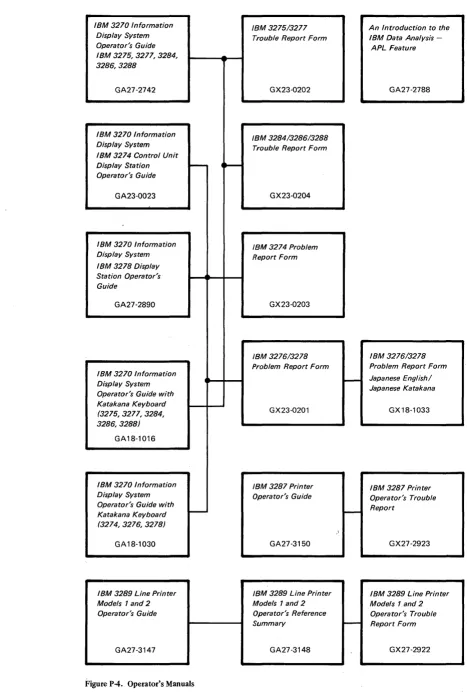
Figure P-4. Operator's Manuals
vi
r
IBM 3270 Information Display System 3278 Display Station Problem Determination Guide *GA27-2839
IBM 3287 Printer
Problem Determination Guide *
GA27-3151
System Problem Determination for 3274 Control Units
GA27-2871
IBM 3270 Information Display System 3274 Control Unit Problem Determination Guide *
GA27-2850
IBM 3270 Information Display System 3278 Display Station with Katakana Feature Problem Determination Guide
GA18-1032
IBM 3289 Line Printer
Models 1 and 2 Error Recovery and Problem Determination GiJide *
GA27-3141
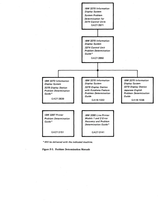
[image:11.618.43.561.44.710.2]* Will be delivered with the indicated machine.
Figure P-S. Problem Determination Manuals
1
IBM 3270 Information Display System 3278 Display Station Japanese English Problem Determination Guide
Chapter 1. Planning and Setup 1-1 Introduction 1-1
3274 Cluster Unit Descriptions 1-1 Configuration Planning 1-2
System Planning 1-2 Site Preparation 1-2
Communication Services (3274-1C) 1-3
Local Channel Attachment (3274-1A, IB, and ID) 1-3 Programming Support 1-4
Encrypt/Decrypt Feature (3274 ModellC Only) 1-4 Prc-Delivery Planning 1-5
3274-lA/IB/ID to Local Channel Cables 1-5 3274-lC Communication Cable 1-5
3274-lC System Grounding 1-5 3274 Device Cables 1-5
3274 Cluster Network Address Labels 1-6 3274 Customizing 1-6
Setup Procedures 1-7
3274-lC Setup Procedures 1-8 3278 Setup Procedures 1-8
3287 and 3289 Setup Procedures 1-8 Replacing a 3271 or a 3272 with a 3274 1-8 Problem Determination Procedures 1-9 Relocation/Removal 1-10
Progress Review 1-10
IBM Americas/Far East and IBM Europe/Middle East/Africa 1-10 Supplemental Information 1-10
Safety 1-10 Security 1-11
Personnel Training 1-11 Supplies 1-11
Voice Communication between 3274 Cluster Operators and Host System Operators 1-11
Reference Manuals 1-11
Chapter 2 Introduction to Customizing 2-1
Chapter 3. Preparing to Customize 3-1 3274 ModellA Customizing 3-3
001 Keyboard Validation 3-3 011 Patch Request 3-3
021 Printer Authorization Matrix 3-3
022 Printer Authorization Matrix Specification 3-3 031 RPQ Diskettes Required 3-4
111 Number of Category B Terminals 3-4 112 Number of Category A Terminals 3-5 113 Extended Function Store 3-5 121 Keyboard/Character Set Language 3-6 131 Typewriter Keyboard 3-6
132 Data Entry Keyboard 3-6
133 Data Entry Keypunch Layout Keyboard 3-6 134 APL Keyboard 3-7
135 Test Keyboard 3-7 141 Magnetic Slot Reader 3-7
143 Host-Loadable Printer Authorization Matrix 3-7 145 3289 Text Print Control 3-7
147 3-7
151 3274 Model Designation 3-7 201 Control Unit Address 3-7 211 SCS Support 3-7
213 Between Bracket Printer Sharing 3-7 301 3-7
302 3-7
310 through 352 3-7
900 Entry Acceptance
901 Printer Authorization Matrix Acceptance 3-8 999 Modify Proced ure 3-8
3274 Models IB and ID 3-9 001 Keyboard Validation 3-9 011 Patch Request 3-9
021 Printer Authorization Matrix 3-9
022 Printer Authorization Matrix Specification 3-9 031 RPQ Diskettes Required 3-10
111 Number of Category B Terminals 3-10 112 Number of Category A Terminals 3-12 113 Extended Function Store 3-12 121 Keyboard/Character Set Language 3-12 131 Typewriter Keyboard 3-12
132 Data Entry Keyboard 3-12
133 Data Entry Keypunch Layout Keyboard 3-12 134 APL Keyboard (Model1D Only) 3-12 135 Test Keyboard (Model1D Only) 3-12 141 Magnetic Slot Reader 3-12
143 Host-Loadable Printer Authroization Matrix 3-13 145 3289 Text Print Control 3-13
147 Local Copy Function (ModellD Only) 3-14 151 3274 Model Designation 3-14
201 through 252 3-14 900 Entry Acceptance 3-14
901 Printer Authorization Matrix Acceptance 3-14 999 Modify Procedure 3-14
3274 Model1C 3-15
001 Keyboard Validation 3-15 011 Patch Request 3-15
021 Printer Authorization Matrix 3-15
022 Printer Authorization Matrix Specification 3-15 031 RPQ Diskettes Required 3-16
111 Number of Category B Terminals 3-16 112 Number of Category A Terminals 3-17 113 Extended Function Store 3-17 121 Keyboard/Character Set Language 3-18 131 Typewriter Keyboard 3-18
132 Data Entry Keyboard 3-18
133 Data Entry Keypunch Layout Keyboard 3-19 134 APL Keyboard 3-19
135 Test Keyboard 3-19 141 Magnetic Slot Reader 3-19
143 Host-Loadable Printer Authorization Matrix 3-19 145 3289 Text Print Control 3-19
147 Local Copy Function (BSC Only) 3-19 151 3274 Model Designation 3-19 201 3-19
211 SCS Support (SDLC Only) 3-19 213 Between Bracket Printer Sharing 3-19 301 Control Unit Number (BSC Only) 3-19 302 SDLC Control Unit Address 3-20 310 Modem Connection 3~20
311 Modem Wrap 3-20
313 NRZI (SDLC) or NRZ Encoding 3-21 314 Multipoint or Point-to-Point Network 3-21 317 Nonswitched or Switched-Network Backup 3-21 318 Normal or Half-Speed Transmission 3-21 321 EBCDIC or ASCII Character Set 3-21 331 BSC or SDLC Protocol 3-22
342 RTS (Request to Send) Control (2-wire or 4-wire) 3-22 343 DDSA (Dataphone** Digital Service Adapter) 3-22
**Trademark of American Telephone and Telegraph Co.
352 Encrypt/Decrypt 3-22 900 Entry Acceptance 3-22
901 Printer Authorization Matrix Acceptance 3-22 999 Modify Procedure 3-22
Chapter 4. Initial Customizing Procedure 4-1 Initial Customizing Procedure Form 4-3 Printer Authorization Matrix Form 4-15
Chapter 5. Modification Procedure 5-1 Modification Procedure Form 5-3 Printer Authorization Matrix Form 5-15
Chapter 6. Backup System Diskette Generation Procedure 6-1 Backup System Diskette Form 6-3
Chapter 7. Update-Diskette Installation 7-1
Update-Diskette Installation Procedure for IBM 3274 Control Unit 7-3
Figures
Figure P-l. Figure P-2. Figure P-3. Figure P-4. Figure P-5. Figure 2-1. Figure 3-1.Figure 3-2.
Figure 3-3.
Figure 3-4.
Figure 3-5.
Figure 3-6.
Figure 3-7. Figure 4-1. Figure 4-2. Figure 4-3. Figure 4-4. Figure 4-5. Figure 4-6. Figure 4-7.
Figure 5 .. 1.
viii
General Information and Installation Manuals ii
Customer Setup Manuals iii
Programming Manuals iv Operator's Manuals v
Problem Determination Manuals vi Configuration Information Needed 2-3
3274 ModellA Category A and B Terminal Quantity Relationships 3-5
3274 ModellA Keyboard/Character Set Languages 3-6
3274 Models 1B and 1D Category A and B Terminal QJantity Relationships 3-11
3274 Models 1B and 1D Keyboard/Character Set Languages 3-13
3274 ModellC Category A and B Terminal Quantity Relationships 3-17
3274 ModellC Keyboard/Chara:cter Set Languages 3-18
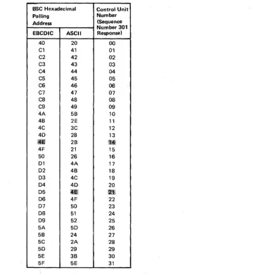
BSC Polling Address/Control Unit Number Conversion Chart 3-20
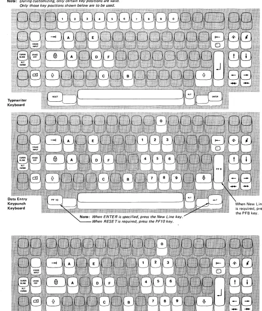
Valid Key Positions during Customizing 4-7 Valid Key Positions during Customizing when Using Japanese Katakana and Japanese English
Keyboards 4-8
Inserting a Diskette into the 3274 4-9 Operator Codes during Customizing 4-10 Steady 8421 Indicator Codes during Customizing 4-11
Flashing 8421 Indicator Codes during Customizing 4-12
8421 Indicator Codes during IML that Result from an Incorrect Customizing Procedure 4-13
Valid Key Positions during the Modification Procedure 5-7
Appendix B. 3274 Device Cables B-1
Instructions for Completing the 3274 Device Cable Attachment Form B-2
3274 Device Cable Attachment Procedure B-3 3274 Device Cable Attachment Form B-5 Channel Attachment Information Form
(3274-1A, lB, and 1D) B-7
Appendix C. Printer Authorization Matrix C-1 The 3274 Printer Authorization Matrix C-1 Defming the Printer Authorization Matrix During
Customizing C-3
Abbreviations Abbreviations-1
Figure 5-2. Figure 5-3. Figure 5-4. Figure 5-5. Figure 5-6. Figure 5-7. Figure 6-1. Figure 6-2 Figure 6-3. Figure 6-4. Figure 6-5. Figure 6-6. Figure 6-7. Figure C-l. Figure C-2. Figure C-3. Figure C-4.
Valid Key Positions during the Modification Procedure When Using Japanese Katakana and Japanese English Keyboards 5-8
Inserting a Diskette into the 3274 5-9 Operator Codes during the Modification Procedure 5-10
Steady 8421 Indicator Codes during the Modification Procedure 5-11
Flashing 8421 Indicator Codes during the Modification Procedure 5-12
8421 Indicator Codes during IML that Result from an Incorrect Modification Procedure 5-13
Valid Key Positions during Backup System Diskette Generation 6-6
Valid Key Positions during Backup System Diskette Generation When Using Japanese Katakana and Japanese English Keyboards 6-7
Inserting a Diskette into the 3274 6-8 Operator Codes during Backup System Diskette Generation 6-9
Steady 8421 Indicator Codes during Backup System Diskette Generation 6-10
Flashing 8421 Indicator Codes during Backup System Diskette Generation 6-11
8421 Indicator Codes during IML that Result from an Incorrect Backup System Diskette Generation 6-12 Example of a Printer Authroization Matrix C-3 Example of a Completed Printer Authorization Matrix Form C-4
Printer Authorization Matrix Worksheet Example C-5
Introduction
This planning and setup guide will help you plan the installation of the IBM 3274 Control Unit Models lA, lB, and 10 and/or the setup of the following 3270 Information Display System units:
IBM 3274 Control Unit ModellC IBM 3278 Display Station IBM 3287 Printer
IBM 3289 Line Printer
These units have convenient customer access areas to which your personnel can attach the cluster cables and the keyboard and feature cables.
The 3274 (all models), 3278, 3287, and 3289 units are delivered with unpacking instructions attached to an outside surface of the shipping carton. In addition to the unpacking instructions, the 3274-1 C, 3278, 3287, and 3289 units have setup instructions inside the shipping carton. The unpacking instructions and the setup instructions are step-by-step procedures that describe the unpacking and setup tasks for the unit. The 3274 must also be customized for the unique cluster configuration.
Chapters 2, 3, and 4 provide the information needed to prepare for, and to customize, all models of the 3274. Included is a suggested form to use when customizing the 3274. Chapter 2 also describes the procedure for installing update diskettes sent to you from time to time by IBM. Chapter 5 provides the information and procedure to modify a system diskette. Chapter 6 provides the information and procedure to generate a backup (duplicate) system diskette. Chapter 7 provides the information needed and the pro-cedure for installing an updated diskette package.
Using the planning information in this guide will help you to insure that your personnel can (1) unpack, position, set up, customize (3274), and check out the 3274-1C, 3278, 3287, and 3289 units, and (2) unpack, position, attach the device cables (coaxial cables that connect the 3274 to the attached units) to, and customize the 3274-1A, lB, and 10 without the help of IBM service representatives (an IBM service representative will install the 3274-1A, 1B, and 1D). As a result, you will be able to use your new display/printer cluster at an early date. If, later, you choose to improve the work flow by relocating these units within the site, your personnel should be able to accomplish the relocation (the help of an IBM service representative is needed to relocate a 3274-1A, lB, or 10).
3274 Cluster Unit Descriptions
The 3274 cluster consists of an IBM 3274 Control Unit with attached display stations and/or printers.
For detailed information about the functions and features of the 3274 and the units that can be attached to the 3274, see the latest editions of:
An Introduction to the IBM 3270 Information Display System, GA27-2739
IBM 3270 Information Display System: Component Description, GA27-2749 IBM 3270 Infornuztion Display System Character Set Reference, GA27-2837
System Planning
Site Preparation
1·2
To plan the configuration of the 3274 and the attached units, use the appropriate (U.S., Americas/Far East, or Europe/Middle East/Mrica) Configuration Tables in IBM 3270 Information Display System: Configurator, GA27·2849. These tables will help you determine which feature codes are needed to:
• Connect the:
a. 3274·lA, lB, or lD to a host system through a local channel. b. 3274·lC to a host system through communication facilities. • Provide the required quantity of 3274 terminal adapters. • Provide feature compatibility among the individual units.
The tables also indicate necessary features, optional features, prerequisite features, and features that cannot coexist.
The following tasks should be planned so that they can be accomplished in a timely manner:
• Site preparation for the 3274 clusters
• Communication facilities preparation for 3274·lC • Host system channel preparation for 3274·lA, lB, and lD • Programming support preparation
• 3274 pre·delivery planning activities
It may be useful to designate to a person in your organization the responsibility of ensuring that all these tasks are planned. The Planning Checklist in Appendix A of this guide contains the events, in a suggested sequence, that should ~e planned in order to install a 3274·lA, lB, or lD and/or set up a 3274·lC and the attached units for the first time; it, therefore, contains more detail than is required for adding to or replacing an existing display/printer system. In either case, each event should be carefully considered so that installing the 3274·lA, lB, or ID and/or setting up the 3274·lC and the attached units is problem·free.
The specifications for all physical requirements of the 3274, 3278, 3287, and 3289 units are given in IBM 3270 Information Display System: Installation Manual - Physical Planning, GA27·2787.
This guide will help you provide compatibility between these units and the following: • Work space considerations
• Electrical requirements
between the 3274-IC and the host communication unit/adapter. There must be compatibility between the 3274-IC, the modems, the communication line, and the communication unit/adapter; for example, line speed, duplex or half-duplex facilties, and NRZ (non-return to zero) or NRZI (non-return to zero inverted).
Compatibility among these components is a major consideration in new installations. To reduce delays caused by incompatibility, it is recommended that you request assistance from your communications representative and from your IBM representative to determine whether the 3274-IC, modems, communication line, and communication unit/adapter are compatible. In addition, schedules should be established to ensure that the modems, communication line, and communication unit/adapter are installed and tested before delivery of the 3274-IC and the attached units.
Local Channel Attachment (3274-IA, IB, and ID)
A plan needs to be established for the changes that are required to your host system selector, multiplexer, or block multiplexer channel configuration; considerations should include device priorities, device data rates, device addresses, I/O interface cable lengths, and changes to the sequence and control (power sequencing and emergency power off) cables.
The Channel Attachment Information Form in Appendix B should be completed before the 3274 is delivered. This information will be required by the IBM service representative at the time of installation. The following information will assist you in completing the form. For further information, see the IBM System/370 Installation Manual - Physical Planning, GC22-7004. The 3274-IA, IB, and ID may be attached to a byte multiplexer, block multiplexer, or selector channel. In most cases the choice of channel attachment depends on system considerations such as channel utilization rather than 3274 operation.
Selector or Block Multiplexer Channel (Non-Byte Mode Operation): If you choose to attach the 3274-IA, IB, or ID to a block multiplexer or selector channel, the following options should be selected:
1. Select the IOOKb data rate (Model IA only).
2. Select burst mode for Model IA. No selection is required for Models IB and ID. 3. Select the priority that will produce the greatest channel efficiency with other
attached devices. Factory wiring of high priority is recommended.
The 3274-IA, IB, and ID are designed to operate with disconnect command chaining (DCC). Therefore, they will provide greater channel efficiency on a block multiplexer channel than on a selector channel.
Byte Multiplexer Channel (Byte Mode Operation): If you choose to attach the 3274-IA, IB, or ID to a byte multiplexer channel, the following considerations and selections should be made:
1. a. Select byte mode for Model lAo
b. Select burst mode for Models IB and ID only if the 3274 is the only device on the channel. In all other cases select byte mode.
2. Select a priority that is below all overrun able devices on the channel. This can be accomplished by channel cabling between devices and/or the channel priority options.
Programming Support
utilization with other devices attached to the same channel. There is no data rate selection option on the Models 1B and 1D.
When choosing a control unit address for the 3274-1A anyone of the 256 possible addresses may be used. The 3274-1B and 1D are very similar to the 3272. The hexadecimal address of the control unit must be a multiple of hex 10 (hex 00, hex 10, hex 20, etc.). If more than 16 devices are attached, the control unit address must be a multiple of hex 20 (hex 00, hex 20, hex 40, etc.).
The 3274-1B and ID also require an address range. Calculate the number of contiguous addresses as follows:
8 X Number of Type A Terminal Adapters
+ 4 X Number of Type B Terminal
AdaptersFor ex~ple, a control unit address of hex 20 with 2 Type A Terminal Adapters and 3 Ty.p~ B Terminal Adapters would be 16
+ 12
=
28. Therefore, 28 is the number of contiguous addresses. The 3274-1B and ID will then respond to addresses hex 20thrOli~,~ex 3B.
It is important to plan for proper programming support at the host system. The 3274 clusters' can be added to most 3270 display/printer systems with minimal impact on the existing programs. In certain cases, however, host system definition (SYSGEN) parameters will have to be changed to accommodate attachment of a 3274 cluster. Informatioq concerning programming requirements is included in the following publica-tions: '
An Introduction to the IBM 3270 Information Display System, GA27-2739
Introduction to Programming the IBM 3270, GC27-6999
IBM 3270 Information Display System: Component Description, GA27-2749
In addition, it is recommended that for 3274 clusters you enhance your system availability and serviceability by installing the Online Test Executive Program (OLTEP) at the host system. Contact your IBM representative for information about OLTEP.
Encrypt/Decrypt Feature (3274 Model lCOnly)
1-4
on the otlJ,ir hand, is set up by your personnel. To prevent delays and help ensure a smootheri' installation/setup , it is recommended that a designated person in your organization:
1. Compile the installation-dependent information described in this section
2. Distribute the installation-dependent information to the appropriate personnel or the IBM service representative
3. Coordinate the activities of your personnel and/or the IBM service representative
3274-1A/IB/ID to Local Channel Cables
3274-1C Communication Cable
3274-1 C System Grounding
3274 Device Cables
The I/O interface and power sequencing cables between a 3274-IA, IB, or ID and a local channel will be installed and connected by IBM. However, these cables must be ordered by cable order unless you are replacing a 3272 with a 3274, in which case, the same cables can be used.
The communication cable that connects the 3274-1C to the modem or channel service unit is delivered with the 3274-1 C. The standard cable length is 6.1 metres (20 feet); optional cable lengths of 3.0 metres (10 feet), 9.1 metres (30 feet), and 12.2 metres (40 feet) may be specified. This cable is connected to the 3274-IC by the setup personnel. Instructions for connecting the communication cable to the 3274-IC are provided by the 3274 Setup Instructions delivered with the 3274-IC. Connection to the modem or channel service unit should be discussed with your supplier.
Frame ground (EIA RS232 or CCITT V.28 pin 1) and signal ground (EIA RS232 or CCITT V.28 pin 7) should be connected together at one point only. This can be either in the 3274-IC or in the modem or channel service unit. If possible, it is recommended that this connection be made in the modem or . channel service unit.
In Europe/Middle East/ Africa countries the majority of modems do not have this connection made. For this reason connection has been made within the 3274-IC at the plant of manufacture.
Note: If you are replacing a 3271 or 3275 with a 3274-1C, the modem should already have signal ground and frame ground connected together. However, this should be verified with your communications supplier.
Fan-Out Feature: This feature perml~ts two or more control units to be connected to a single modem. If the model has this' capability, it is imperative that the signal ground and frame ground wires be connected together in the modem.
The device cables are the coaxial cables that connect' the 3274 to its attached display stations and printers. These cables sh~uld be procured and installed before the delivery of the 3274 and the units which WIll be attached to the 3274. Your personnel (or contractor) will connect these cables t'o the 3274 and the attached units.
Note: If you are replacing a 3271 or a 3272 with a 3274, you can use the existing device cables between the 3271/3272 and the attached units. However, the 3271 or 3272 device cables must be connected/disconnected by an IBM service representative, because the 3271 and 3272 and the attached units do not have customer access areas. Before the IBM service. representative disconnects these cables, it is recommended that you have the cables marked as described below.
mended that each cable be marked at both ends to identify:
• The 3274 connector panel type (Category A panels or Category B panels) and the 3274 port (0 to 31) to which it is to be connected
• The unit type to be attached
For additional information concerning device cables, refer to IBM 3270 Information Display System: Installation Manual - Physical Planl'Jing, GA27-2787.
A 3274 Device Cable Attachment form is provided in Appendix B of this guide to help simplify marking and connecting the cables. Instructions for completing all portions of the form except Network Addresses and using the form are also included in Appendix B. A form should be completed for each 3274 cluster you order. Copies of the completed form should be given to the personnel who will install and mark the cables and the personnel who will connect the cables to the 3274. In addition, a copy of the form should be stored in the pocket inside the 3274 customer access door for future reference.
3274 Cluster Network Address Labels
3274 Customizing
1-6
Hexadecimal address labels (IBM Part 1743290) are delivered with the 3274. (They will be found, together with a Problem Report Form and Configuration Data card, in the pocket inside the 3274 customer access door.) After each cluster unit is set up, the labels that specify the unit's network address should be attached to the unit's address label holder (if present).
It is recommended that a designated person in your organization (I) obtain the cluster network addresses from the system programmer, (2) enter the addresses in the Network Address column of the 3274 Device Cable Attachment form in Appendix B, and (3) distribute the network addresses information to the,person who will attach the address labels.
For information concerning SNA network addresses, refer to Systems Network Architecture General Information: Network Addresses, GA27-3102; for information concerning BSC network addresses, refer to IBM 3270 Information Display System: Component Description, GA27-2749.
Once installation of a 3274-IA, IB, or ID Control Unit by your IBM service representative (or your own setup of a 3274-IC) is completed and device cables have been connected, you are ready to configure. your system of displays and printers.
Setup Procedures
• When you initially customize your system diskette (as described above).
• When you wish to duplicate your system diskette. (This new diskette is referred to as a backup diskette.)
• When you wish to generate a second system diskette to be used for a different purpose. For example, you may choose to have one system diskette to operate in BSC mode and another to operate in SDLC/SNA mode .
• When you need to recustomize your system diskette because you have changed your configuration.
Detailed procedures for performing these tasks are provided in Chapters 2 through 6.
In general, the person who customizes the system diskette uses a language diskette and a feature diskette in conjunction with the customizing procedure. The language diskette is used to customize the system diskette for languages other than English (U.S.) and Canada/French (both are EBCDIC), and the ASCII (U.S.)* character set. The feature diskette is used to customize the system diskette for all other cluster parameters. The detailed customizing procedures explain when to insert the required diskettes and direct the person c~stomizing the 3274 to enter the configuration information into the 3274 through a 3278 Display Station attached to port AO of the 3274.
To simplify the customizing task, it is recommended that the planner compile the configuration information' and supply it to the person responsible for performing the customizing procedure. Included in Chapter 3 are descriptions of the parameters to be entered and instructions for completing the Initial Customizing Procedure Form (Chapter 4). A form should be completed for each 3274 ordered prior to delivery of the unit. In addition, configuration information should be copied on the Configuration Data card (shipped with the 3274) and stored in the 3274. (A pocket, located on the inside of the 3274's customer access door, is a convenient place to store this card.)
Each 3274-1C, 3278, 3287, and 3289 unit is delivered with its own:
• Unpacking instructions attached to an outside surface of the shipping carton • Setup instructions
• Problem Determination Guide (PDG)
Note: Retain the package marked for the IBM service representative.
Before each unit is unpacked and placed in its prepared location, the personnel who will unpack and place the units should read the unpacking instructions.
After the unit is unpacked and put in place, the setup personnel should perform the step-by-step procedures in the setup instructions. If the setup personnel encounter difficulties during the checkout portion of the setup instructions, they should use the procedures in the Problem Determination Guide to find the problem. The problem determination procedures should be performed before the service representative is called.
*The ASCII character set is available in the U.S. only.
3274-1C Setup Procedures
3278 Setup Procedures
and to give you a general idea of what is involved. It is not intended to replace the setup instructions delivered with the individual units.
It is recommended that the setup instructions be obtained and read before the units are delivered. These instructions may be ordered as Forms GA27-28SS (3274-1 C), GA27-2838 (3278), GA27-31S2 (3287), and GA27-3140 (3289).
The 3274 lA, IB, and ID are installed by an IBM service representative, because special skills and tools are needed to install these units. The IBM service representative will install the 3274-1A, IB, or ID after your personnel have unpacked and placed the unit. Mter the IBM service representative completes the 3274-1A, IB, or ID installation, your personnel will be able to connect the device cables and customize the 3274-1A, IB, or ID.
Mter the 3274-1C is unpacked and placed in its prepared location, the 3274-1C setup involves:
• Connecting the communication cable to the 3274-1C.
• Plugging in the power cord and switching on the 3274 power. • Inserting the diskettes.
Note: 3274-1C customizing and device cable attachment are not 3274-1C setup procedures; customizing and device cable attachment are performed after the 3274-1C setup is completed.
After the 3278 is unpacked and placed in its prepared location, the 3278 setup involves:
• Connecting the keyboard cable to the 3278.
• Connecting the device cable(s) (coaxial cable from the control unit) to the 3278 or to the Switch Control Unit feature.
• Connecting the magnetic slot reader (if present) to the 3278. • Plugging in the power cord and switching on the 3278 power. • Performing the 3278 checkout procedures.
3287 and
3289Setup Procedures
Mter the 3287 or 3289 is unpacked and placed in its prepared lpcation, the setup involves:
• Plugging in the power cord and switching power on. • Performing the 3287 or 3289 checkout procedures.
• Connecting the device cable (coaxial cable from the control unit) to the 3287 or 3289.
Replacing a 3271 or a 3272 with a 3274
1-8
the power receptacle must be changed prior to installation of the 3274. See IBM Information Display System: Installation Manual - Physical Planning, GA27-2787 for the type required.
When a 3271 is replaced by a 3274-1C, the existing 3271 device cables and modem can be used with the 3274-1C. However, the device addresses of the existing 3277/3284/3286/3288 units and the communication cable that connects the 3271 to its modem cannot be used with the 3274-1C. A new communication cable is delivered with the 3274-1C. The standard cable length is 6.1 metres (20 feet); optional cable lengths of 3.0 metres (10 feet), 9.1 metres (30 feet), and 12.2 metres (40 feet) may be specified.
If the existing 3271 or 3272 device cables are to be used with the 3274, it is recommended that the cables be marked as described under "3274 Device Cables."
Notes:
1. The 3277 keyboards and operator ID card readers cannot be used with the 3278. 2. The 3274, when operating in BSC mode, functions as a 3271 Control Unit, but is not compatible with the 3275 Display Station. See IBM 3270 Information Display Station Component Description, GA27-2749, for an explanation of the differences.
When a 3271 or a 3272 is replaced by a 3274, the following should be considered: • The 3274 can control up to sixteen 3277s/3284s/3286s/3288s. Therefore, more
than one 3274 is required to replace a 3271 or 3272 that has more than 16 of these units attached.
• The 3274 needs a 3278 attached to port AO. Therefore, a 3278 must be added to the existing units.
Note: All the 3271 or 3272 cluster cables must be connected/disconnected by an IBM service representative, because the 3271 or 3272 and the attached units do not have customer access areas.
Problem Determination Procedures
The problem determination procedures will help you perform problem determination with minimai reliance on the host system. These procedures use tests contained in the 3274, 3278, 3287, and 3289 units. See Figure P4, "Problem Determination Manuals" in the Preface.
The procedures enable you to determine whether a problem is being caused by a cluster unit, a system unit or function outside the 3274 cluster, or an operator error. You will also be able to determine whether:
• Operation in a degraded mode is possible.
• Useful work can be done until the problem is corrected. • The repair action can be scheduled for deferred maintenance.
If you require the help of an IBM service representative, the error message and error condition information should be recorded on a problem report form for the failing unit before the service representative is called. This information will help the service representative resolve the problem as soon as possible.
Relocation/Removal
Progress Review
To ensure proper handling and/or shipping of the 3274 and the attached 3278s/3287s/3289s when the units are removed or relocated to a different room, building, or mailing address, it is recommended that you call your local IBM branch office. Your IBM representative will supply you with the necessary information and can order the required materials.
Note: The help of an IBM service representative is required to relocate a 3274-1A, lB,
or lD.
To ensure a smooth installation of the 3274-1A, IB, or ID and/or setup of the 3274-1C and its attached units, it is recommended that approximately two months before delivery of the units you and the IBM representative review (1) the progress (or the schedule associated with the changes) at the host system site, (2) the communica-tion network and modems, (3) the physical changes needed at the cluster site, and (4) the progress of the pre-delivery planning tasks. At the same time, you and the IBM representative can review· the cluster configuration to determine whether the feature mix is adequate.
It is also recommended that about two weeks before delivery of the units a designated person in your organization and the setup personnel review the setup instructions with the IBM representative.
IBM Americas/Far East and IBM Europe/Middle
East/ Africa
Supplemental Information
Safety
I
1-10
The pre~delivery/setup responsibilities and procedures for the 3274-1C, the 3278, the 3287, and the 3289 are the same for U.S. installation and for countries served by IBM A/FE and IBM E/ME/A.
If you need IBM publications in languages other than English, ask your IBM representative. The IBM representative can provide information concerning the avail-ability of translated IBM publications.
The 3270 units are listed by the Underwriters' Laboratory. Exposed hazardous voltages are not present at the designated customer access areas of the 3274, 3278, 3287, and 3289 units.
DANGER
Your personnel should be warned not to go beyond the customer access areas, because there are hazardous voltages within the areas designated for trained personnel only.
Security
Personnel Training
Supplies
If the 3274 and the attached units have access to proprietary records or personnel records, it is recommended that you implement appropriate safeguards for the security of the information and the units. IBM makes available some basic functions, but you should decide which ones to use. In addition to safeguards that you may develop, the Security Keylock and Magnetic Reader Control features, and the Magnetic Slot Reader accessory may be ordered for 3278s. Also available with the 3274-1C is an Encrypt/ Decrypt feature that enhances data security in an SNA-communications environment.
If you intend to provide formal training for your operators, you can use the following operator's guides as texts:
• IBM 3274 Control Unit Operator's Guide, GA23-0023 • IBM 3278 Display Station Operator's Guide, GA27-2890 • IBM 3287 Printer Operator's Guide, GA27-3150
• IBM 3289 Line Printer Models 1 and 2 Operator's Guide, GA27-3147
The operator's guides describe the basic capabilities of the 3270 units. It is recom-mended that you use this information to prepare operating procedures for your unique operations. Problem determination guides for the 3274, 3278, 3287, and 3289 are available to assist operators in determining when an error has been made or when the equipment is not performing properly.
The following supplies may be required, depending upon the types of terminals, devices, and features installed .
• Ribbon: Black, IBM Part 1136653 or a customer-selected equivalent, used by the 3287-1 and 2.
• Ribbon: Black, IBM Part 1136634 or a customer-selected equivalent, used by the 3289-1.
• Ribbon: Black, IBM Part 1136670 or a customer-selected equivalent, used by the 3289-2.
• Paper: Single-part continuous or multipart (six-part maximum) for the 3287s .and 3289s. See Forms Design Reference Guide for Printers, GA24-3488.
• Spare magnetic stripe cards.
• Hexadecimal address labels: IBM Part 1743290. • Mercury Battery: IBM Part 1743456.
Voice Communication between
3274Cluster
Operators and Host System Operators
Reference Manuals
It is recommended that a telephone be available at each location to allow the 3274 cluster operators to talk with the host system operators. This will assist the operators in performing the problem determination procedures as well as the daily work.
See the Preface for a list of publications that may help you to plan the installing of your equipment.
The 3274 Control Unit allows the user to specify the config'lration under which the 3274 operates. Specification of the 3274 configuration is dorl~ by the "customizing procedure." This chapter describes how and by whom the customizing procedure is performed.
Customizing a 3274 Control Unit usually involves a planner and an operator or someone responsible for the actual customizing operation. The planner identifies and compiles the configuration information needed for each 3274 and gives it to the operator, who, following a prompting sequence at a 3278 Display Station (with keyboard) attached to the 3274, enters the information. The operator is prompted by a series of sequence numbers which are displayed in the form of three digits; the responses are usually 1- or 2-digit entries. The 3278 that is used for this operation must be attached to port AO of the 3274; it should be near the 3274 during the customizing operation and be clearly identified for the operator.
Using Figure 2-1 as a guide, and with the sequence number descriptions in Chapter 3, the planner prepares a list of the responses to be entered. The operator, following the list, enters each response on the 3278 keyb oard as each sequence number is displayed. If the entry is acceptable, the display changes to the next sequence number. If the entry is not acceptable, a 1- or 2-digit operator code (Figure 5-4) is displayed at the top center of the screen to identify the problem. At the end of the series of sequence - numbers, the 3278 displays all the responses entered to permit verification and
correction of the entries.
To prepare for customizing, it is recommended that the planner:
1. Use Chapter 3 as a guide to determine what configuration information is needed for each 3274 model. Figure 2-1 and the sequence number descriptions identify the information sources.
2. Using Figure 2-1 as a guide and the sequence number descriptions in Chapter 3, compile the needed information for each 3274.
Note: The sequence number descriptions contained in Chapter 3 are grouped as follows:
3274 MadellA
3274 Models lB and iD
3274 ModellC
3. Identify each diskette. A label in the upper right corner of the diskette identifies the diskette type by name, IBM part number, and validation number. The IBM part numbers are:
Feature diskette System diskette Language diskette
5718400 5718420 5718440
In addition, you may wish to write some unique designation of your own on the label. For example, you could specifically identify it as to configuration, 3274 Control Unit in which it is to be customized and used, etc.
2-2
Chapter 4:
a. The type of keyboard (typewriter or data entry) to be used by the operator. Note: If using a 76- or 88-key Japanese English or Japanese Katakana keyboard, specify the number of keys and keyboard type.
b. In step 1, the identification of each diskette to be used.
c. In step 7, enter the response to sequence number 031. This is the number (0-3) of RPQ diskettes to be used.
d. In step 8, use as a guide the information in Chapter 3 that applies to the model to be customized and enter the responses to be keyed in by the operator.
5. If the printer authorization matrix is to be defined, or if changes are to pe made to the existing matrix, fill out the Printer Authorization Matrix Form at the end of Chapter 4.
6. The following should be given to the operator who will customize the 3274: a. Completed Initial Customizing Procedure Form
b. Completed Printer Authorization Matrix Form (if required) c. Copy of the "Operators Codes" chart (Figure 4-4)
d. Copies of the "8421 Indicator Codes" charts (Figures 4-5,4-6, and 4-7)
e. Copy of the appropriate keyboard layout showing valid keys (Figures 4-1 and 4-2) f. Feature and system diskettes, and language diskette (if applicable)
g. RPQ diskette ( s) (if applicable)
001 Keyboard validation X X X X 1 -
-011 Patch request X X X X 1 -
-021 Printer authorization matrix X X X X 3 O=No 1=Yes
022 Printer authorization matrix specification X X X X 1 See text
-031 RPQ diskettes required X X X X 2 O=Not required1 =One diskette required 2=Two diskettes required 3=Three diskettes required 111 Number of Category B terminals X X X X 2 See text
112 Number of Category A terminals X X X X 2 See text 113 Extended function store X X X 2 See text 121 Keyboard/character set language X X X X 2 See Figure 3-2 131 Typewriter keyboard X X X X 2 O=None
1=Yes 132 Data entry keyboard X X X X 2 O=None
1=Yes 133 Data entry keypunch-layout keyboard X X X X 2 O=None
1=Yes 134 APL keyboard X X X 2 O=No
1=Yes 135 Text keyboard X X X 2 O=No
1=Yes 141 Magnetic slot reader X X X X 2 A=No B=Yes 143 Host-Ioadable printer authorization matrix X X X X 3 O=No
1=Yes 145 3289 Text print control X X X X 3 O=No
1=Yes 147 Local copy function X X 3,5 O=No
1=Yes
151 3274 model designation X X X X 2 A, B, C, D Model 201 Control unit address X 3 See text 211 SCS support X X 2 O=No
1=Yes 213 Between bracket printer sharing X X 3 O=No
1=Yes 301 Control unit number (BSC only) X 3 See text 302 SDLC control unit address X 3 See text 310 Modem connection X 2 O=Other
1=CCITT 108.1 311 Modem wrap X 2 O=Not possible
1=Possible 313 NRZI encoding (SDLC only) or NRZ X 2,4 O=NRZ
1=NRZI 314 Multipoint or point-to-point network X 2,4 O=Multipoint
1 =Point-to-point
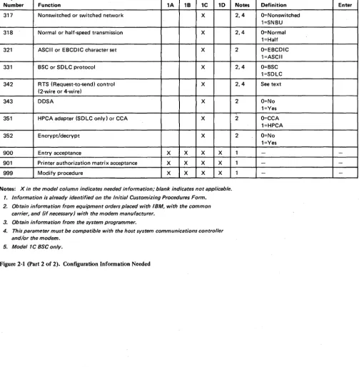
Figure 2-1 (part 1 of 2). Configuration Information Needed
Number Function 1A 18 1C 10 317 Nonswitched or switched network X
318 Normal or half-speed transmission X
321 ASCII or EBCDIC character set X
331 BSC or SDLC protocol X
342 RTS (Request-to-send) control X
(2-wire or 4-wire)
343 DDSA X
351 HPCA adapter (SDLC only) or CCA X
352 Encrypt/decrypt X
900 Entry acceptance X X X X 901 Printer authorization matrix acceptance X X X X 999 Modify procedure X X X X
Notes: X in the model column indicates needed information; blank indicates not applicable.
1. Information is already identified on the Initial Customizing Procedures Form. 2. Obtain information from equipment orders placed with IBM, with the common
carrier, and (if necessary) with the modem manufacturer. 3. Obtain information from the system programmer.
4. This parameter must be compatible with the host system communications controller and/or the modem.
[image:29.617.40.543.76.589.2]5. Model 1C BSC only.
Figure 2-1 (part 2 of 2). Configuration Information Needed
2-4
Notes Definition Enter 2,4 O=Nonswitched
1=SNBU 2,4 O=Normal
1=Half 2 O=EBCDIC
1=ASCII 2,4 O=BSC
1=SDLC 2,4 See text
2 O=No 1=Yes 2 O=CCA
1=HPCA 2 O=No
1=Yes
1
-
-1 -
-This chapter supplies the necessary information to permit the planner to fill in the Initial Customizing Procedure Form in Chapter 4. Chapter 3 is divided into three groups, according to model number. The first group contains information for customizing the 3274 Model lA; the second for customizing the 3274 Models IB and ID; and the third for customizing the 3274 Model 1 C. Select the group that applies to the model to be customized and fill in the replies in step 8 of the Initial Customizing Procedure Form in. Chapter 4. The sequence numbers are listed here and on the form in numerical order, however they may not be displayed on the 3278 screen in numerical order. Although all sequence numbers are listed in each group, only those required for the model being customized are explained. All others instruct the planner to fill in a zero response on the Initial Customizing Procedure Form. This is necessary because all sequence numbers will be displayed to the operator after the responses are keyed in. The sequence numbers that are not applicable to the model being customized will be filled in with zeros on the 3278 screen.
3274 Model 1 A Customizing
001 Keyboard Validation
011 Patch Request
Use the following descriptions in conjunction with the Initial Customizing Procedure Form in Chapter 4 to customize a 3274 ModellA.
The response required for this sequence number is already entered on the form in step 4; it verifies that the keyboard at the 3278 is operating properly. Note that the last two digits (digits following the space) in the response to sequence number 001 identify the Validation Number that must be used in the customizing procedure. This number must be the same as the Validation Number on the feature and system diskette labels.
Note: If a data entry keypunch layout keyboard is used, the New Line key is pressed when ENTER is specified. Also, the PF10 key is pressed when RESET is required; the PF8 key is pressed when New Line is required. See Figures 4-1 and 4-2 for valid key positions and the differences just noted. Be sure to specify the keyboard type on the Initial Customizing Procedure Form.
The response required for this sequence number is already entered on the form in step 5. The service representative may use this sequence number to make a diskette patch request.
021 Printer Authorization Matrix
Enter a 0 in step 6 on the Initial Customizing Procedure Form if any of the following conditions apply:
• The printer authorization matrix is to be entered only by a host application program (a 1 must be specified in sequence number 143).
• All printers are to be used in system mode and local copy operations are not desired. • No printers are to be attached to the system.
Enter a 1 if a matrix is to be defined, thereby causing sequence number 022 to be displayed. This matrix will be established for each 3274 IML, regardless of the response to sequence number 143.
022 Printer Authorization Matrix Specification
The printer authorization matrix is defined in sequence number 022 by use of the following parameters:
AA M XXXX YYYY YYYY
These parameters are entered by the operator who performs the customizing procedure. The Printer Authorization Matrix Form contains spaces for entering the parameters. These parameters correlate to the displayed entry as follows:
AA=Printer port address (01-31) M=Printer mode
O=System l=Local 2=Shared
XXXX=Printer class assignments
Composed of a 4-digit hexadecimal value, this field is bit-encoded and specifies which class(es) the printer will operate in.
YYYY YYYY=Source Device Ust
Composed of two 4-digit hexadecimal values,. this field is bit-encoded and specifies which display(s) may be copied by the printer.
031 RPQ Diskettes Required
Refer to Appendix C for detailed infonnation concerning the printer authorization matrix parameters.
Fill in the appropriate spaces on the Printer Authorization Matrix Form with a defmition for each printer in your configuration, and attach it to the Initial Customizing Procedures Form to give to the operator who will perform the customizing procedure. The definitions ma,y be entered in any sequence. Also, definitions do not have to be entered successively; for example, you may enter definitions in groups I, 2, and 3 of the form, skip groups 4 and 5, and continue at group 6.
Once a printer authorization matrix has been defined, sequence number 021 is no longer displayed when a customized 3274 Control Unit is being updated. Instead, the defined matrix is displayed. If the entire matrix is deleted, sequence number 021 will again be displayed during each updating procedure until a new matrix is defined. Any time the initial customizing procedure is performed, the sequence number 021 is displayed and the printer authorization matrix must be redefined if it is still required.
Enter the number of RPQ diskettes required (1-3) in step 7 of the Initial Customizing Procedures Form. Enter a
a
if none are required.111 Number of Category B Terminals
3-4
Enter a 2-digit number (00 to 16) specifying the number of Category B terminals that it is possible to attach to your 3274. (The actual number you have attached at any given time may be fewer than this number.)
Notes:
1. A 2-digit number must be entered. If necessary, use a leading zero. For example, to specify 8, enter 08.
2. Category A terminals:
3278-1, -2, -3, -4
3287-1, -2 with 3274/3276 attachment (#8331) 3289-1, -2
Category B terminals:
3277-1, -2 3284-1, -2 3286-1, -2
3287-1, -2 with 3271/3272 attachment (#8330) 3288-2
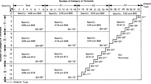
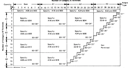
3a. Specify the number of Category A terminals in mUltiples of 8 (maximum of 32) and the number of Category B terminals in multiples of 4 (maximum of 26), unless the sum of the two categories exceeds 32.
3b. If the sum of the two categories exceeds 32:
• For Category B terminals, specify the actual number of Category B terminals (sequence number 111).
• For Category A terminals, specify the difference between 32 and the·number of Category B terminals (sequence number 112).
Quanti ty
~
0 1 2
1:
B13 4 5 6
fIIH
ca
.~~
m 82
> 7
8 9 10
&H
! CII u....
o...
1: B3 11 12 13 14
~t4
84 -1Base
..
-2 3 4 5 6 7 8 9 Specify: A08 and 800Specify: A08and B04
BO=08*
Specify: A08 and B08
BO=08*
Specify: A08 and B12
80=08*
Specify:
Number of Category A Terminals
A1
.
-
-
A2.
.
10 11 12 13 14 15 16 17 18 19 20 21 22 23 24 Specify: A16and 800 Specify: A24 and 800Specify: Specify: A16 and B04 A24 and B04
BO=16* BO=24*
Specify: Specify: A16 and B08 A24 and B08
BO=16* BO=24*
--25
A3
..
-26 27 28 29 30 31 32 Specify: A32 and 800BO=3
I
Specify: BO=30* 32-8=A BO=29*
BO=28* BO=27* 80=26* BO=25* Adapter Type
1 *
BO=23* Specify: Specify: 80=22*
Not A16 and B12 32-B=A
80=21* Permitted BO=16* BO=20*
BO=19* Specify: BO=18* 15 A08 and B16 A16 and B16 BO=17* 16 80=08* BO=16*
g
Adap,", Type*The host-recognized port addresses are sequencial with the first Category A port (port AO) always being address 0 (with the exception of SNA, which is always 02). The first Category B port (port BO) is always the next sequencial address after the last Category A port.
Figure 3-1. 3274 ModellA Category A and B Tenninal Quantity Relationships
112 Number of Category A Terminals
Enter a 2-digit number (08 to 32) specifying the number of Category A terminals that it is possible to attach to your 3274. (The actual number you have attached at any given time may be fewer than this number.)
113 Extended Function Store
Enter one of the following to specify whether any, and which, Extended Function Store feature is installed:
0000
=
No Extended Function Store is installed.3622
=
Extended Function Store feature type C 1 (#3622) is installed.5000
=
Extended Function Store feature type Cl (#3622) and C3 (#3625) is installed.7000
=
Extended Function Store feature type Cl (#3622) and Dl (#3627) is installed.9000
=
Extended Function Store feature type C 1 (#3622), C3 (#3625), and D 1 (#3627) is installed. [image:34.612.58.567.68.350.2]121 Keyboard/Character Set Language
131 Typewriter Keyboard
132 Data Entry Keyboard
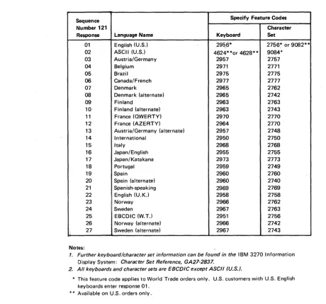
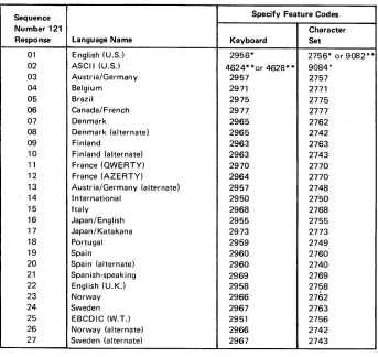
Enter a 2-digit number (01 to 27) from Figure 3-2 specifying the keyboard/character set language being used. A 2-digit number must be entered. If necessary, use a leading zero. For example, to specify 8, enter 08.
Sequence Specify Feature Codes
Number 121 Character
Response Language Name Keyboard Set
01 English (U.S.) 295_6* 2756~ or 9082** 02 ASCII (U.S.) 4624**or 4628** 9084*
03 Austria/Germany 2957 2757 04 Belgjum 2971 2771 05 Brazil 2975 2775 06 Canada/ French 2977 2777 07 Denmark 2965 2762 08 Denmark (alternate) 2965 2742 09 Finlanq 2963 2763 10 Finland (alternate) 2963 2743 11 France (QWERTY) 2970 2770 12 France (AZERTY) 2964 2770 13 Austria/Germany (alternate) 2957 2748 14 International 2950 2750 15 Italy 2968 2768 16 Japan/English 2955 2755 17 Japan/Katakana 2973 2773 18 Portugal 2959 2749 19 Spain 2960 2760 20 Spain (alternate) 2960 2740 21 Spanish-speaking 2969 2769 22 English (U.K.) 2958 2758 23 Norway 2966 2762 24 Sweden 2967 2763 25 EBCDIC (W.T.l 2951 2756 26 Norway (alternate) 2966 2742
Ii 27 Sweden (alternate) 2967 2743 Notes:
1. Further keyboardlcharacter set information can be found in the IBM 3270 Information Display System: Character Set Reference, GA27-2837.
2. All keyboards and character sets are EBCDIC except ASCII (U.S.).
* This feature code applies to World Trade orders only. U.S. customers with U.S. English keyboards enter response 01.
** Available on U.S. orders only.
Figure 3-2. 3274 Model lA Keyboard/Character Set Languages
Enter a 0 if none of the attached 3278s have a typewriter keyboard (#2715,2727,4621, 4624,4627,4628) or a 1 if any do.
Enter a 0 if none of the attached 3278s have a data entry keyboard (#2716, 4622) or a 1 if any do.
133 Data Entry Keypunch Layout Keyboard
3-6
[image:35.618.86.547.120.549.2]134 APL Keyboard
135 Text Keyboard
141 Magnetic Slot Reader
Enter a 0 if none of the attached 3278s have an APL Keyboard feature (#4626) or a 1 if any do.
Note: If neither an APL nor a text keyboard is attached to any 3278 but you wish to display or print APL and/or text characters, enter a 1.
Enter a 0 if none of the attached 3278s have a Text Keyboard feature (#4629) or a 1 if any do.
Enter an A if none of the attached 3278s h