Control of a Stewart Platform Used in Biomechanical
Systems Using Fuzzy Logic Controller
Mohammad Amin Rashidifar
1,*, Ali Amin Rashidifar
2, Abdolah Abertavi
31Department of Mechanical Engineering, Islamic Azad University, Shadegan Branch, Iran 2Department of Computer Science, Islamic Azad University, Shadegan Branch, Iran 3Department of Electrical Engineering, Islamic Azad University, Shadegan Branch, Iran
Copyright©2016 by authors, all rights reserved. Authors agree that this article remains permanently open access under the terms of the Creative Commons Attribution License 4.0 International License
Abstract
The paper is focused on the analysis of the Stewart platform to be used in the development of a device for the determination of mechanical properties of materials used for substituting spinal segments of human bodies. At the present time, the Stewart platform is widely used and its popularity is due mainly to the following facts, in comparison with serial mechanisms: higher stiffness, better dynamic properties of the mechanism, higher accuracy of the mechanism, precise and easy positioning. Simulations are conducted for the determination of an acceptable control system based on fuzzy logic. A controller description is included.Keywords
Stewart Platform, Biomechanics, Fuzzy Controllers1. Introduction
Owing to closed kinematic structure, Stewart platform (SP) mechanism has more stiffness and load-carrying capacity in comparison with mechanisms composed as open kinematic chains. Originally designed by Stewart [2] as mechanism for flight simulation, Stewart platform has used in many applications today (milling machine and high speed machine tools, ‘pick-and-place’ applications, medical surgery, etc.). The basic platform structure has been slightly modified and partially improved from the original design by Stewart up to now. Gough applied linear actuated legs structure for the tire test machine. Thus, this mechanism is sometimes called Stewart-Gough platform in certain referral sources [3, 14, 15]. The Stewart platform consists of two rigid platforms, one is fixed to the ground and the other is moveable. It has 6 degrees of freedom (DOFs). The platforms are connected by six extendable legs. Such construction provides very good payload, high load/weight ratio with extremely good dexterity and mobility. These are the reasons why investigation of Stewart platform attracts the attention of
many researches around the world. In [4] general form of Stewart platform was considered proving the existence of 3850 possible solutions of SP design, obtained by combining different kind of joints and constrains. Authors showed how to realize generalized Stewart platform in various fields. Dynamic analysis of Stewart platform is subject of many researches that used different kinds of control strategies. In these works SP is energized in different ways. Hydraulic actuated SP is subject of research in [8] where virtual prototype of hydraulic actuated Stewart force feedback master-slave system (using PID controller) is developed using MATLAB-Simulink program. The inverse models for the system kinematics and dynamics of hydraulic actuated Stewart platform are developed using Matlab in [13]. In [12] a piezo stack actuators for effectively damping of the SP vibration was analysed. Dynamic modelling of electrically actuated SP is subject of research in [9], where Kane’s equation is used for analysis of the driven torque of motors. Stewart platform, driven by permanent magnet synchronous motor, is analysed in [10]. Closed-form dynamic equations of mechanism and actuator are derived using Lagrangian method and simulation is performed by using MATLAB-Simulink in [6]. Comparison of two control strategies – PID and generalized predictive control is realized in [7]. Using genetic algorithm by Matlab, the methodology for design optimization of 6 DOF active vibration isolation system based on Stewart platform is presented in [11].
that the lower plate is firmly connected to the base, the upper plate is able to move with six degrees of freedom. At the present time, the Stewart platform is widely used and its popularity is due mainly to the following facts, in comparison with serial mechanisms:
higher stiffness, better dynamic properties of the mechanism, higher accuracy of the mechanism precise and easy positioning, and wide range of
movements.
The objective of the paper is to analyze the Stewart platform and to conduct simulations to evaluate the obtained results with a fuzzy logic controller. In order to conduct the analysis, a fuzzy logic controller has been implemented.
2. Cinematic Model
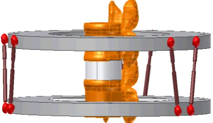
The use of the Stewart Platform is universal. In biomechanics it has been used in experimental backbone modelling and in experimental modelling of biomechanical problems of large human joints. In Figure 1, it is shown the 6 degrees of movement generated by six extensible legs and the static lower plate (considered individually) with the upper plate which generate all the translations and rotations on the axis. In order to derive the cinematic model of the Stewart platform, it is used a simple model consisting of a base and a platform which are the center of the platform and the other six coordinate systems are located in the base of each extensible leg. The cinematic model for this case has been presented in [1].
Figure 1. Scheme of Device for Testing Spinal Elements.
3. Dynamic Model (State Space Model)
To generate each movement it is necessary to use an actuator or motor connected to the upper plate of the platform, having fixed the lower platform. This dynamic model was developed first using the Newton-Euler Dynamical Equations and then converted into a MIMO state space model [3]. This model is implemented in MATLAB-SIMULINK. The analysis has been based on the
Newton-Euler Dynamic Equations, using the vector equations of equilibrium of torques and forces instead of matrix operation.
The following set of equations for the Stewart platform is obtained:
dt
dz
k
t
p
F
dt
z
d
m
2=
zz−
(
)
−
2 (1)dt
dy
k
t
p
F
dt
y
d
m
2=
zy−
(
)
−
2 (2)dt
dx
k
t
p
F
dt
x
d
m
2=
zx−
(
)
−
2 (3)dt
d
dt
d
I
I
t
p
M
dt
d
m
zz y xθ
φ
y
(
)
(
)
2 2
−
−
−
=
(4)dt d dt d I I t p M dt d
m
φ
2 zy ( ) ( x z)θ
y
2
− − −
= (5)
dt
d
dt
d
I
I
t
p
M
dt
d
m
zx z yy
φ
θ
)
(
)
(
2 2−
−
−
=
(6)Where Fzx, Fzy ,Fzz, Mzx, Mzy, Mzz are the forces and
torques around each axis; m is the mass of the upper plate; Iz, Iy, Ix are the respective inertia values and
θ
,φ
,y
are therespective angles to x, y, and z axis. State space equations were developed for the simulation:
(7)
The model has been linearized using the Jacobian matrix, due to the nonlinear characteristics of the dynamic equations.
)
(
3 3 0 6 0 60
U
t
M
F
V
X
J
A
I
A
X
+
=
(8)X
I
Y
=
12 (9)Where
A0 = 6 x 6 zero matrix
I6 = 6 X 6 identity matrix
J6 = 6 X 6 inertia matrix that is shown next,
[image:2.595.72.293.456.583.2]
− −
− −
− −
−
=
0 0
0 0
0 0 0
0
0 0 0 0
0 0 0 0
0
0 0 0 0 0
0 0 0 0 0
1 3
2 2
1 1
S S
S S
S S k/m k/m −k/m
J
y
(10)
Where
V0 = 3×1 zero vector
F3 = 3×1 input forces vector
M3 = 3×1 input torque vector
y z
I
I
S
1=
−
z x
I
I
S
2=
−
x y
I
I
S
3=
−
For the simulation a sinusoidal input U(t) has been used. The following control requirement have been established:
Basic movements
x,y,z position in ±5 mm range (accuracy 0,1 mm) rotation in x,y,z axes in range ±10° (accuracy 0,5°) loading Fx,y,z = 2000 N (accuracy 1 N), Mx,y,z ±10
Nm (accuracy 0,5 Nm)
4. Design of the Fuzzy Controller
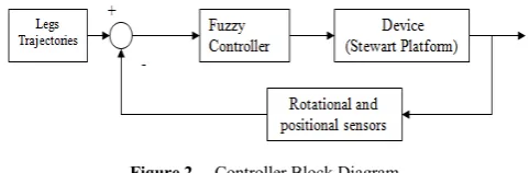
[image:3.595.56.297.555.634.2]The selected controller structure is shown in the block diagram in Figure 2 [6]. The design of the membership functions has been accomplished using data generated from the dynamic model referred before. From previous practical studies, it has been found that the random forces lie in the range of -2000 N and 2000 N and the torque in the range of -15 N.m and 15 N.m approximately, the obtained values were compared for the translations and rotations on each axis, using the forces and torques applied at the input of the system.
Figure 2. Controller Block Diagram.
The range of each membership function was selected as per the results given by the software, using the inductive reasoning method [4]. The 12 selected inputs for the fuzzy system are:
Translation errors : 3 variables in the X, Y, and Z
respectively (ex,ey,ez)
Rotation errors (3 variables), velocities (3variables) and angular velocity errors (3 variables)
The 6 outputs of the fuzzy system are: Forces (3 variables Fx, Fy, Fz) Torques (3 variables Tx, Ty,Tz)
For the design of the membership functions 2 steps were applied to determine the range of the membership functions:
Clustering
Inductive reasoning Algorithm
A clustering algorithm is needed as a preprocessing step before finding the range of each membership function, because it gives an idea on how the data is sort, then the inductive reasoning method is applied in order to find the overlapping of each membership function. K-mean algorithm method has been used for sorting the data and forming the clusters. The method is based on the partitioning of a given set of data points into a number of distinct groups, called clusters. The partition is made looking for the maximum similarity of points into clusters, using some global measure. The k-means algorithm attempts to find the cluster centers (c1,...,ck) in which the norm D of each data
point (xi) is minimized to its nearest cluster center (ck) [6].
∑
= =
=
ni k
d
x
kic
kD
1
2
) ... 1 (
(
,
)
min
(11)The algorithm consists of the following steps: 1. Initialize K center locations (c1,...,ck).
2. Assign each xi to its nearest cluster center.
3. Update each cluster center ck as the mean of all xi have
been assigned as closest to it as possible. 4. Calculate D
5. If the value of D converged, then return (c1,...,ck).; else
go to step 2.
It’s important to notice that different clustering algorithms may be used: Hard C means, Fuzzy Hard C means etc. This is just a preprocessing step that will be used later in the partitioning process of the membership functions.
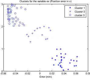
Figure 3. Clusters for the Variable “ex”
In order to find the boundaries of each membership function and the center of each cluster, the method of inductive reasoning is applied. The inductive reasoning method is used for the segmentation of attributes for each fuzzy set and the discriminant power of each attribute is used in an iterative method called dichotomizer, the partition and discriminant power of an attribute are determined by a measurement called entropy. The following equations are used in the inductive reasoning method (Castro J. L. and J. M. Zurita)
1
)
(
1
)
(
)
(
+
+
=
x
n
x
n
x
p
kk ;
(
)
1
1
)
(
)
(
+
+
=
x
n
x
n
x
q
kk ;
)
(
1
)
(
x
p
x
q
=
−
;n
x
n
x
p
(
)
=
(
)
(12)1
( )ln ( )
kp i i
i
S
p x
p x
=
= −
∑
(13)∑
=
−
=
ki i i
q
q
x
q
x
S
1
)
(
ln
)
(
(14)Where
pk= Proportion of samples of k class to the right of the
partition
qk = Proportion of samples of k class to the left of the
partition
p= Proportion of samples to the right of the partition q= Proportion of samples to the left of the partition. nk = Number of samples of k.
N= Number of sample in the whole partition. Sp= Entropy to the right of the partition.
Sq= Entropy to the left of the partition.
A complete mapping of the universe of discourse and the point where the minimum entropy is obtained will be considered as the first partition r1. Repeating this process to
the left and right of this point r k partitions are obtained, in
which the number of membership functions is:
k
r
n
µ=
(15)µ
n
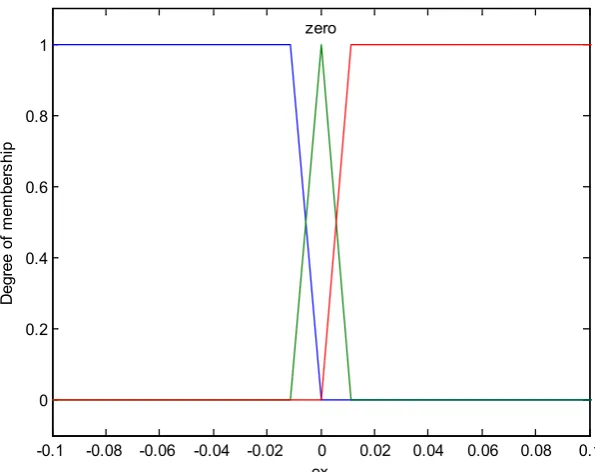
= number of membership functions.The obtained membership functions resulting from the partition of the variable “error in X (ex)” are shown in Figure 4.
-0.060 -0.04 -0.02 0 0.02 0.04 0.06 0.08 1
2
3 Clusters for the variable ex (Position error in x)
Error (mm)
Figure 4. Resulting Membership Function for the “ex” variable
6. Results Obtained with the Simulation
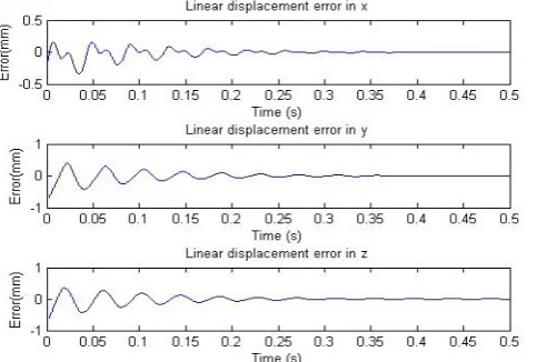
The controllers’ simulations were developed in SIMULINK. As can be seen from Figures 5 and 6, the errors of the time response for the fuzzy controller reach the stability in 0.15 sec approximately. A PID controller has been designed in order to compare its response with that of the fuzzy controller. The control signal (input for the dynamic system) are the six legs forces generated by the actuators, and the output signals are the angular and linear positions.
The gains for the PID controller (
K
d,K
i andK
p) were selected by trial and error.Kd = 7000; Kp = 20000; Ki = 4000
The stability with the PID controller is obtained in 0.5 sec. approximately. For both it is desirable to lower this time.
In a real application, the fuzzy logic controller uses less hardware than a PID controller, because it’s not necessary to use amplification to generate the feedback’s gain in order to reduce the steady state error.
Fuzzy control systems are a good option in this type of application, due to the nonlinear characteristics of the Stewart platform even if it is necessary to consider other kind of nonlinear characteristics such as coriolis, gravity effects and centrifugal forces. The time response of the PID controller can be
improved, but if the gains (
K
d,K
i andK
p) areincreased, the system could be unstable or saturated. Sometimes the PID controller is not enough to get an acceptable time response of the system, due to
intrinsic vibrations. Usually it becomes necessary to use a compensator such as a
H
∞ controller in orderto reduce vibration effects [Se-Han Lee, et al., 2003]. Table 1 shows the settling time for each controller. From this table it can be seen that, under the design conditions, the fuzzy controller settling time is lower than the PID settling time.
Table 1. Controllers settling time
Fuzzy Controller PID Controller
Settling Time (s) 0.2073 0.500
Settling Time (s) 0.2070 0.500
Settling Time (s) 0.2072 0.500
Figure 5. Results Obtained for the Fuzzy Controller.
-0.1 -0.08 -0.06 -0.04 -0.02 0 0.02 0.04 0.06 0.08 0.1 0
0.2 0.4 0.6 0.8 1
ex
D
egr
ee of
m
em
ber
shi
p
[image:5.595.312.551.464.737.2]Figure 6. Results Obtained with the PID Controller.
7. Conclusions
An analysis of the Stewart platform has been developed. These platforms present advantages in comparison to other mechanical structures used in the development of biomechanical devices due to their flexibility, easy and precise positioning, and wide range of movement.
A fuzzy and a PID controller are presented as good alternatives for the control system due to the nonlinear behavior of the controlled device. The obtained results show the advantages of the fuzzy logic controller, because the PID controller yield a bigger settling time in comparison with the fuzzy logic controller even with high gain constants also, it is easier to implement the fuzzy controller.
REFERENCES
[1] V. Damic, J. Montgomery, Mechatronics by Bond Graphs, Springer-Verlag, 2003.
[2] D. Stewart. "A platform with six degrees of freedom", Proc. of institute for Mechanical Engineering, London, Vol.180, pp. 371-386, 1965.
[3] S-K. Song, D-S. Kwon, New direct kinematic formulation of 6 D.O.F. Stewart-Gough platforms using the tetrahedron approach, Transactions on Control, Automation and System Engineering 4 (2002) pp.217-223.
[4] X-S. Gao, D. Lei, Q. Liao, G-F. Zhang, Generalized Stewart platforms and their direct kinematics, MM Research preprints,
MMRC, AMSS, Academia, Sinica, Beijing, 22 (2003) pp.64-85.
[5] V. Damic, M. Cohodar, M. Kulenovic, Modeling and simulation of hydraulic actuated multibody systems by bond graphs, Procedia Engineering 69 (2014) pp.203-209. [6] A. El-Badawy, K. Youssef, On modeling and simulation of 6
degrees of freedom Stewart platform mechanism using multibody dynamic approach, ECCOMAS Multibody Dynamics 2013, 1-4 July 2013, University of Zagreb, Croatia, pp. 751-760.
[7] Z. Bingul, O. Karahan, Dynamic modeling and simulation of Stewart platform, Serial and parallel robot manipulators – kinematics, dynamics, control and optimization, Ed. by S. Kucuk, Publisher In Tech, ISBN 978-953-51-0437-7, pp.19-42.
[8] J. M. Rosario, D. Dumur, M. Moretti, F. Lara, A. Uribe, Supervision and control strategies of 3 DOF parallel manipulator using mechatronic approach, Advanced strategies for robot manipulators, Ed. By S. Ehsan Shafiei, Publisher Sciyo, ISBN 978-953-307-099-5, pp. 173-196. [9] H. Jingwei, Z. Dingxuan, Z. Ying, C. Yuxin, Simulation
research on hydraulic Stewart force feedback Master-Slave system, Proceeding of the 2nd International Conference on Computer Science in Electronics Engineering (ICCSEE 2013), Published by Atlantis Press, France, pp.2440- 2443. [10] Q. Meng, T. Zhang, J-F. He, J-Y. Song, J-W. Han, Dynamic
modeling of 6-degree-of-freedom Stewart platform driven by permanent magnet synchronous motor, Computer & Electron. 11(10) (2010) pp.751-761.
[11] R.U. Baig, S. Pugazhenthi, Design optimization of an active vibration isolation system, International journal of the physical sciences 6 (30) (2011) pp.6882-6890.
[12] A. Bahrami, M. Tafaoli-Masoule, M. N. Bahrami, Fuzzy Logic Based Active Vibration Control of Piezoelectric Stewart Platform, International Journal of Mechanical, Industrial Science and Engineering Vol. 8 No. 1 (2014) pp.72-79.
[13] A. Bose, R. Saha, K. Majumdar, D. Sanyal, A simple design approach for hydraulic Stewart platform through Matlab simulation, Proceedings of the 1st International and 16th National Conference on Machine and Mechanism (iNaCoMM2013) India (2013) pp.757-764.
[14] A.-F. Behrouz, P. Lidstrom, K. Nilsson, Parametric damped vibrations of Gough-Stewart platforms for symmetric configuration, Mechanism and Machine Theory, 80 (2014) pp.52-69.
[image:6.595.60.311.81.244.2]