i
STRUCTURAL BEHAVIOUR OF PRECAST LIGHTWEIGHT FOAMED CONCRETE SANDWICH PANEL (PLFP) WITH SHEAR TRUSS
CONNECTORS
GOH WAN INN
A thesis submitted in
fulfilment of the requirement for the award of the Doctor of Philosophy.
Faculty of Civil and Environmental Engineering Universiti Tun Hussein Onn Malaysia
v
ABSTRACT
vi
ABSTRAK
vii
CONTENTS
TITLE i
DECLARATION ii DEDICATION iii ACKNOWLEDGEMENT iv
ABSTRACT v
CONTENT vii
LIST OF TABLES xiii
LIST OF FIGURES xvi
LIST OF SYMBOLS AND ABBREVIATIONS xxiii
LIST OF APPENDICES xxvii
CHAPTER 1 INTRODUCTION 1
1.1 Introduction 1 1.2 Problem statement 3 1.3 Research objectives 4
1.4 Significant of study 4 1.5 Scopes of study and limitation of study 4 1.6 Thesis layout 5
CHAPTER 2 LITERATURE REVIEW 7
2.1 Introduction 7
viii
2.2.4 Normal concrete capping 15
2.3 Accuracy of structural models 15
2.3.1 Scale model technique 16
2.4 Finite element analysis 19
2.4.1 Comparison of conventional FEA software 20 2.4.2 Abaqus/Explicit versus Abaqus/Standard 22 2.4.2.1 Choosing between implicit and explicit analysis 24
2.4.3 Element types 24
2.4.3.1 Continuum elements 25
2.4.3.2 Eight node brick element with reduced integration
(C3D8R) 26
2.4.3.3 Shell elements 27
2.4.3.4 Beam elements 27
2.4.3.5 Truss elements 27
2.4.3.6 Rigid body 28
2.4.3.7 Selecting continuum elements 29
2.4.4 Materials modelling by using concrete damaged
plasticity 30
2.4.4.1 Capabilities of concrete damaged plasticity model 33 2.4.4.2 Parameters of concrete damage plasticity 33 2.4.4.3 Previous research by using concrete damage
plasticity 37
2.4.5 Geometrical imperfection 38
2.4.5.1 Minimum initial curvature in column or wall system 40 2.4.5.2 Maximum initial curvature in column or wall system 40 2.4.5.3 Modelling of geometrical imperfections in FEA 42 2.4.6 Previous structural research by using FEA 44 2.5 Previous research on precast sandwich panel 48
2.5.1 Advantages of sandwich panel 49
2.5.2 Previous experimental research on sandwich panel
with single shear truss connectors 49
2.5.3 Previous experimental research on sandwich panel
ix
2.5.4 Previous experimental research on other types
of sandwich panel 58
2.5.5 Summary of previous research on precast sandwich
panel 61
2.6 Previous developed empirical equations for wall
elements 62
2.6.1 Empirical equation from ACI318-89 63
2.6.2 Empirical equation from BS8110 64
2.6.3 Empirical equation from Eurocode 2 64 2.6.4 Empirical equation from previous researchers 65 2.6.5 Comparison of previous developed empirical
equations for wall elements 70
2.7 Conclusion 72
CHAPTER 3 RESEARCH METHODOLOGY 74
3.1 Introduction 74
3.2 Material testing 76
3.2.1 Laboratory testing for mechanical properties of
foamed concrete 76
3.2.1.1 Compressive strength of foamed concrete cube 77 3.2.1.2 Splitting test of foamed concrete cylinder 77 3.2.1.3 Compression test of foamed concrete cylinder 78 3.2.2 Mechanical properties of foamed concrete 78 3.2.2.1 Compressive strength of foamed concrete 79 3.2.2.2 Tensile strength of foamed concrete 80 3.2.2.3 Young’s Modulus and Poisson ratio of foamed
concrete 80
3.2.3 Tensile test on steel bar reinforcement 81 3.3 Experimental investigation on PLFP panel 82 3.3.1 Material properties of PLFP panels 83 3.3.2 Designation and dimension of PLFP panels 84
3.3.3 Fabrication and casting 86
x
3.5 Summary 90
CHAPTER 4 EXPERIMENTAL STUDY OF PLFP PANEL 91
4.1 Introduction 91
4.2 Ultimate load carrying capacity of PLFP panel 91
4.3 Crack pattern and mode of failure 93
4.4 Load versus horizontal deflection 95
4.5 Load –strain relationship on the wythe surface 96
4.6 Conclusion 99
CHAPTER 5 NUMERICAL SIMULATION OF PLFP PANEL 100
5.1 Introduction 100
5.2 Objectives 101
5.3 Description of the finite element model 101
5.3.1 Element types of each materials 101
5.3.2 Boundary condition and load application 103
5.3.3 Parameters of PLFP panel 106
5.4 Modelling of material properties 107
5.4.1 Material properties of foamed concrete 107
5.4.2 Material properties of normal concrete capping 110
5.4.3 Material properties of main reinforcement and shear connectors 111
5.4.4 Material properties of polystyrene 111
5.5 Quasi-static analysis of PLFP panel 112
5.6 Convergence study of PLFP panel 114
5.7 FEA verification 115
5.7.1 Validation of ultimate load carrying capacity 116
5.7.2 Failure mode of PLFP panel with single shear truss connectors 116
5.7.3 Validation of load versus vertical displacement profile 117
5.7.4 Validation of load versus horizontal displacement profile 118
5.7.5 Imperfection FEA model versus experiment 119
xi
5.8 Parametric study of PLFP panel with double shear
truss connectors under axial loading 124
5.8.1 Ultimate load carrying capacity for PLFP panel with double shear truss connectors 124
5.8.2 Failure mode of PLFP panel from FEA 126
5.8.3 Load versus vertical displacement 133
5.8.4 Load versus horizontal displacement 135
5.8.5 Strain distribution across PLFP panel’s thickness 137
5.8.6 Stress distribution 139
5.8.7 Post failure 140
5.8.8 Effects of various thicknesses of polystyrene 145
5.8.9 Effects of various thicknesses of foamed concrete wythe 146
5.9 Effects of double shear truss connectors on PLFP panel 148
5.9.1 FEA of PLFP panel under push off loading 149
5.10 Summary of structural behaviour for PLFP panel with shear truss connectors 153
5.10.1 PLFP panel under axial loading 153
5.10.2 PLFP panel under various slenderness ration and thickness 154
5.10.3 Failure mode of PLFP panel 154
5.10.4 Effects of PLFP panel with double and single shear truss connectors 155
5.10.5 Sustainability of PLFP panel as load bearing wall in low to medium rise building 155
5.11 Conclusion 155
CHAPTER 6 DEVELOPMENT OF EMPIRICAL EQUATION 157
6.1 Introduction 157
6.2 Comparison of results from FEA and empirical equations 157
6.3 Previous developed empirical equations 159
6.4 Proposed empirical equation 164
xii
CHAPTER 7 CONCLUSION AND RECOMMENDATIONS 173
7.1 Introduction 173
7.2 Conclusion for each objective 173
7.2.1 Objective 1 173
7.2.2 Objective 2 174
7.2.3 Objective 3 175
7.2.4 Objective 4 176
7.3 Recommendations 177
REFERENCES 178
APPENDICES A-H 184
LIST OF PUBLICATIONS 216
LIST OF COMPETITION PARTICIPATED AND AWARDS 219
xiii
LIST OF TABLES
2.1 Typical mixture details for foamed concrete (BCA, 1994) 8 2.2 Typical properties of foamed concrete (BCA, 1994) 8 2.3 Comparison of strength to density ratio (in MPa per kg/m3
x 1000) (Kunhanandan and Ramamurthy, 2006) 9 2.4 Typical properties of expanded polystyrene
(Texas Foam Inc, 2011) 11
2.5 Scaling laws (Knappet et al., 1996) 16
2.6 Comparison of concrete response (Johnson, 2006) 21 2.7 Comparison of reinforcement response (Johnson, 2006) 22 2.8 Key differences between Abaqus/Standard and
Abaqus/Explicit (Abaqus, 2009) 23
2.9 Concrete damaged plasticity model parameters
(Mokhatar and Abdullah, 2012) 37
2.10 Material parameters of concrete damaged plasticity model
(Newberry et al., 2010) 38
2.11 Test specimens with dimension, aspect ratio and slenderness
ratio of precast reinforced (Benayoune et al., 2007) 50 2.12 Dimension of foamed concrete sandwich panel (Liew, 2011) 52 2.13 Dimension of specimens (Mohamad, Omar and Abdullah 2011) 55 2.14 Dimension of PLFP specimens (Mohamad and Mahdi, 2011) 57 2.15 Axial load capacities for walls taking into account steel
buckling and profiled concrete effects (Wright, 1998) 61 2.16 Summary of previous studies on precast sandwich panel 62 2.17 List of previous researchers and formulas 71 2.18 Summary of tested wall panels and variables used by
previous researchers (Jeung, 2002) 72
3.1 Mixture ratio for foamed concrete casting (Mohamad, 2010) 76 3.2 Compressive strength of foamed concrete at 7th, 14th and
xiv
3.3 Tensile strength of foamed concrete at 28th Day 80 3.4 Young’s Modulus and Poisson Ratio of foamed concrete at
28th Day 81
3.5 Mechanical properties of reinforcement 82
3.6 List of half scaled PLFP panels with 50 mm thickness 84 3.7 List of half scaled PLFP panels with other thickness 84
4.1 Ultimate load carrying capacity of PLFP panel 92
4.2 Crack pattern and failure modes of PLFP panel 94
5.1 Element used for each part of PLFP panel 102
5.2 List of full scaled PLFP panel that were analysed by FEA 106
5.3 Properties of foamed concrete in PLFP panel 107
5.4 Concrete damaged plasticity of foamed concrete 108
5.5 Properties of normal concrete capping in PLFP Model 111
5.6 Mechanic properties of steel assigned for reinforcement and shear connectors in the FEA 111
5.7 Properties of expanded polystyrene 112
5.8 Result of mesh refinement study of PS1 114
5.9 Designation of foamed concrete of PLFP panel with single shear truss connector 116
5.10 Ultimate load carrying capacity of PLFP panel with single shear truss connectors 116
5.11 Imperfection study of PLFP panel by FEA 122
5.12 Ultimate load carrying capacity of PLFP panel’s scale model with double shear truss connectors 123
5.13 Ultimate load of PLFP for perfect and imperfect geometry model in FEA 125
5.14 Mode of failure of PLFP panels with 100 mm thickness from FEA 127
5.15 Failure mode of PLFP panels under axial load from FEA 128
5.16 Mode of failure of PLFP panels with 100 mm thickness from FEA 129
xv
5.18 Ultimate load carrying capacity, vertical displacement for
PLFP panels with various thicknesses of polystyrene 145 5.19 Ultimate load carrying capacity, vertical displacement for
PLFP panels with various thicknesses of foamed concrete 147 5.20 Comparison of ultimate axial load carrying capacity load
achieved for PLFP panels with single and double shear
truss connectors 149
5.21 Comparison of vertical displacement and horizontal displacement for PLFP panels with single and double
shear truss connectors 149 5.22 Comparison of ultimate shear forces achieved for PLFP
panel with single and double shear truss connectors 151 6.1 Comparisons of FEA result versus developed equation
xvi
LIST OF FIGURES
2.1 Strength density variation for mixes with sand of different
fineness (Kunhanandan and Ramamurthy, 2006) 9 2.2 Typical stress/strain curves for expanded polystyrene
(Texas Foam Inc, 2011) 12
2.3 One way shear connectors, stiff in only one direction
(PCI committee, 1997) 13
2.4 Two way shear connectors, stiff in at least two
perpendicular directions. (PCI committee, 1997) 14 2.5 Non-composite connectors (PCI committee, 1997) 14 2.6 Normal concrete capping (Mohamad, Omar and
Abdullah, 2011) 15
2.7 Steel reinforcement for model wall sections
(Gran et al., 1996) 17
2.8 Completed four storey reinforced concrete scale
Building (Vaughan et al., 2011) 18
2.9 Comparison of high speed camera images with equivalent
snapshots from pretest simulation. (Vaughan et al., 2011) 18 2.10 Post failure photos of test article showing collapsed region
compared with snapshot from pretest simulation showing
collapsing section of model (Vaughan et al., 2011) 19 2.11 Common element families in ABAQUS (Abaqus, 2009) 25 2.12 Linear brick, quadratic brick, and modified tetrahedral
elements (Abaqus, 2009) 26
2.13 1x1x1 integration point scheme in hexahedral elements
(Abaqus, 2009) 26
xvii
2.15 Response of concrete to uniaxial loading in tension (Abaqus, 2009), (Jankowial and Lodygowski, 2005; Jason et al., 2004; Lee and Fenves, 1998 and Mokhatar
and Abdullah, 2012) 31
2.16 Response of concrete to uniaxial loading in compression (Abaqus, 2009), (Jankowial and Lodygowski, 2005; Jason et al., 2004; Lee and Fenves, 1998 and Mokhatar
and Abdullah, 2012) 31
2.17 Yield surfaces in the deviatoric plane, corresponding to
different values of . (Abaqus, 2009) 35
2.18 Yield surface in plane stress. (Abaqus, 2009) 35 2.19 Global imperfections (magnified)
(Boissonnade and Somja, 2012) 39
2.20 Local imperfections (magnified)
(Boissonnade and Somja, 2012) 40
2.21 Resultant deflection and curvature profiles to EC2
(Robinson et al., 2011) 41
2.22 Tension zone in a solid eccentrically loaded wall.
(Kuddus, 2010) 41
2.23 Effect of increasing eccentricity on the size of cracked
section (Kuddus, 2010) 42
2.24 Single storey multi-column system: model with initial
Curvature (Artizabal-ochoa, 2012) 43
2.25 Model of an imperfect column with sideway partially inhibited and rotational end restraints: (a) structural model with eccentric axial loads applied at the column extremes: (b) end moments, forces, rotations and deflections: and (c) column segment including bending moments, shear
and axial forces (Artizabal-ochoa, 2012) 43
2.26 An axially loaded column with initial geometric imperfection
(Xu and Wang, 2008) 44
2.27 Energy level of the whole model for analysis with step time equal to (i) 1x natural period (ii) 8x natural period
xviii
2.28 Small scale test set up (left side), Finite element model of one quarter of the four points bending test (right side)
(Joshani et al., 2012) 46
2.29 Total internal energy and kinetic energy of whole slab versus
time (Joshani et al., 2012) 47
2.30 Damage status at concrete when the mid span deflection
reached 2.3 mm (Joshani et al., 2012) 47
2.31 Strain distribution in precast concrete sandwich panel under
flexural bending (PCI committee, 1997) 49
2.32 Details of a typical precast concrete sandwich panel test
specimen (Benayoune et al., 2007) 51
2.33 Typical strain variation across the mid height of the PCSP
at different load stages. (Benayoune et al., 2007) 51 2.34 The detailing of foamed concrete sandwich panel for
thickness 100 mm (Liew, 2010) 53
2.35 The failure of Panel A (Liew, 2010) 54
2.36 Details of specimen (Mohamad, Omar and Abdullah, 2011) 56 2.37 Section of PE-1 (Mohamad and Mahdi, 2011) 57 2.38 Section of PE-2 (Mohamad and Mahdi, 2011) 58 2.39 Failure mode of control wall elements in compression
(Sumadi and Ramli, 2011) 58
2.40 Failure mode of sandwich wall elements without wire
mesh in compression (Sumadi and Ramli, 2011) 59 2.41 Failure mode of sandwich elements with reinforcement
(wire mesh and others) in compression
(Sumadi and Ramli, 2011) 59
2.42 Schematic diagram of composite walling (Wright, 1998) 60 2.43 Notation for wall (British Standard Institution, 2004) 65
3.1 Methodology of study 75
3.2 Compression test of concrete cube 77
3.3 Split cylindrical test 78
3.4 Tension testing result for 9 mm diameter reinforcement 82
3.5 Details of PLFP panel 85
xix
3.7 Polystyrene was placed on top of foamed concrete of the
first wythe layer 87
3.8 Foamed concrete was poured above the polystyrene to form the second wythe layer and trowelled to obtain a smooth
surface 87
3.9 Axial load test frame 88
3.10 Strain gauges (SG) and linear voltage displacement transducers (LVDT) locations 88
3.11 Support condition at bottom end condition of the panel 89 3.12 Top end condition for panel and arrangement for applying pure axial load 89 4.1 Ultimate load carrying capacity versus slenderness ratio for PLFP-HA1 to PLFP-HA8 92
4.2 Ultimate load carrying capacity versus compressive strength for PLFP-HA1 to PLFP-HA8 93
4.3 Crack pattern PLFP-HA3, occurred at upper and lower ends of the panel 94
4.4 Load horizontal deflection curves at mid-height of PLFP-HA6 96
4.5 Load versus strain graphs for HA-2 97
4.6 Load versus strain graphs for HA-5 98
5.1 Structural model of single shear connectors and double shear connectors with main reinforcement 102
5.2 Structural model of PLFP panel 103
5.3 Embedded technique for elements constrains 104
5.4 Rigid body as load cell and spreader beam 105
5.5 Supports and loading condition of PLFP panel in FEA 105
5.6 Compression hardening-softening of foamed concrete 109
5.7 Nonlinear compression strain softening of foamed concrete 109
5.8 Tension stiffening of foamed concrete 110
5.9 Tension damage of foamed concrete 110
xx
5.11 Internal and kinetic energy level of the whole model with
1 natural period 113
5.12 Meshes density study of FEA 115
5.13 Failure mode of PS2 from experiment and FEA 117
5.14 Load versus vertical load displacement for PS1 118
5.15 Comparison of FEA and experimental result of load versus horizontal load displacement for PS1 119
5.16 Perfect and imperfect geometry model of PLFP panel 120
5.17 Load versus horizontal displacement at mid height from experiment and FEA of PS1 panel 121
5.18 Failure mode of PLFP panel from experiment (half scale) and FEA (full scale) 123
5.19 Comparison of ultimate load carrying capacity of PLFP panels based on perfect and imperfect geometry model from FEA 126
5.20 FEA results of load versus vertical displacement for PLFP-1 to PLFP-11 134
5.21 Vertical displacement of PLFP-1 to PLFP-11 134
5.22 Horizontal displacement versus ultimate load of PLFP-1 to PLFP-11at mid height 135
5.23 FEA results of load versus horizontal displacement 136
5.24 General trend of horizontal displacement for PLFP panel 137
5.25 Vertical strains across the thickness along X axis of PLFP-11 in perfect geometry mode 138
5.26 Vertical strains across the thickness along X axis of PLFP-11 in imperfect geometry model 138
5.27 Comparison of stress distribution with damage and crack pattern of PLFP-11 in imperfect geometry model 140
5.28 Damage status of PLFP-11 vertical displacement increments from 0 mm to 50 mm 142
5.29 Stress distribution of PLFP-11 under vertical displacement increments from 0 mm to 50 mm 143
xxi
5.31 Ultimate load versus thicknesses of polystyrene for panel with various heights (3,200 mm, 3,500 mm, 3,600 mm
and 4,000 mm) 146
5.32 Ultimate load versus thicknesses of foamed concrete for panel with various heights (3,200 mm, 3,500 mm, 3,600 mm
and 4,000 mm) 148
5.33 Support and loading condition of push off loading FEA 150 5.34 Comparison of shear force capacity for PLFP panel with
single and double shear truss connectors 151 5.35 Stress distribution of PLFP panel with single shear truss
connectors under the shear force FEA 152 5.36 Stress distribution of PLFP panel with double shear truss
connectors under the shear force FEA 153 6.1 Comparisons of FEA and empirical values from empirical
equation (safety factor included) for ultimate load of PLFP
panels 158
6.2 Comparisons of FEA and empirical values from empirical equations (safety factor excluded) for ultimate load of PLFP
panels 159 6.3 Comparisons of FEA and three closest empirical predictions
for ultimate load carrying capacity of PLFP panels 160 6.4 Percentage difference between ultimate load carrying
capacity from FEA and Equation 6.1 from Eurocode 2 161 6.5 Percentage difference between ultimate load carrying
capacity from FEA and Equation 6.3 from Benayoune
(2007) 163
6.6 Percentage difference between ultimate load carrying capacity from FEA and Equation 6.4 from Mohamad
(2010) 164
6.7 Comparisons of FEA result and developed Equation 6.5
versus slenderness ratio 167
6.8 Percentage difference between ultimate load carrying
xxii
6.9 Relationship between ultimate load carrying capacity and slenderness ratio from FEA, equations by previous
researchers and the proposed Equation 6.5 169 6.10 Ultimate load carrying capacity versus slenderness ratio
from FEA and Equation 6.5 for PLFP panels with 125 mm
and 100 mm thicknesses 170
6.11 Percentage difference between ultimate load carrying capacity from FEA and empirical values proposed from
Equation 6.5 for PLFP panels with 125 mm thickness 171 6.12 Percentage difference between ultimate load carrying
capacity from FEA and empirical values proposed from
xxiii
LIST OF SYMBOLS AND ABBREVIATIONS
b - Overall width of the cross section
B - Length
c/c - centre to centre C - Concrete cover D - Damage parameter e - Eccentricity
E - Young’s Modulus
h - Overall depth of the cross section H - Height of panel
- Aspect ratio
- Aspect Ratio
- Slenderness ratio
k - 0.8 for wall brace top and bottom against lateral translation and restrained against rotation at one or both ends.
K - The ratio of the second stress invariant on the tensile meridian pcf - per cubic foot
t - Overall Thickness Ѱ - Dilatation angle
σ - Stress
- The ratio of initial equibiaxial compressive yield stress to initial
uniaxial compressive yield stress - Initial yield
- Ultimate stress
- Maximum principal effective stress - Uniaxial tensile stress at failure
ε - Strain
xxiv
- Compressive equivalent plastic strains ϵ - Flow potential eccentricity
- Effective length factor, 1.0 for compressive strength of concrete at 28 days ≤ 50MPa
ρ - Density
υ - Poisson Ratio μ - Viscosity parameter
- Temperature
Ф - Diameter of shear connector (mm)
- The strength of reduction factor (0.7 for reinforced member)
- Factor taking into account curvature, including second order effects ASTM - American Standard Test Method
BCA - British Cement Association
BS - British Standard
CFRP - Carbon Reinforced Polymer
CIDB - Construction Industry Development Board of Malaysia CREAM - Construction Research Institute of Malaysia
C3D8R - Continuum three dimensional 8 node linear brick element
EC2 - Eurocode 2
EPS - Expanded Polystyrene foam
EXP - Experimental Result
FE - Finite element
FEA - Finite Element Analysis
HA - Half scale panel
IBS - Industrialized Building System
LVDT - Linear Voltage Displacement Transducers PCI - Precast Concrete Institution
PLFP - Precast Lightweight Foamed Concrete Sandwich Panel PRIMA - 1 Malaysia People’s Housing Programme
PSI - Pounds per square inch
PS - PLFP with single shear truss connectors R&D - Research and Development
xxv
R3 - 3 mm mild steel
R6 - 6 mm mild steel
SG - Strain Gauges
T3D2 - Three dimensional 2 nodes truss element UTHM - Universiti Tun Hussein Onn Malaysia
XPS - Extruded Polystyrene foam
- The gross area of section Asc - The total area of steel used
- Total area of longitudinal reinforcement - uniaxial damage variable due to compression - uniaxial damage due to tension
E - Modulus Young
Eo - Initial (undamaged) elastic stiffness/ initial modulus of the material
ea - An additional eccentricity due to deflections in the wall
ei - Additional eccentricity covering the effects of geometrical
imperfection
eo - First order of eccentricity
etot - eo + ei
fbo/fco - The ratio of initial equibiaxial compressive yield stress to initial
uniaxial compressive yield stress - The compressive strength of concrete
- field variable
fy - The tensile strength of the steel
G - Flow potential
J - Energy
- The ratio of the second stress invariant on the tensile meridian lo - Effective length of the wall
Nu - Design axial strength per unit length of wall (N/mm)
xxvi
t1 - Thickness of concrete wythe
xxvii
LIST OF APPENDICES
APPENDIX TITLE PAGE
A Estimation of loading for 6 storey residential
building 184
B Foamed concrete properties 188
C Results of tension testing on reinforcement 192 D Experimental failure mode and cracking pattern of
PLFP 194
E Data of horizontal deflection and strain for PLFP
panels 197
F Load-horizontal deflection for PLFP panels 205
G Load-strain graphs for PLFP panels 206
CHAPTER 1
INTRODUCTION
1.1 Introduction
As a developing country, housing demand in Malaysia is increasing day by day especially in urban areas such as Kuala Lumpur, Penang, Selangor and Johor Bahru. According to Sultan Sidi (2011) and MacDonald (2011), the high housing prices has become a problem to the majority of local population. It is stated that, the high price of the medium cost apartment, condominiums, terraced houses, the semi-detached and the bungalow units became unaffordable to many. As such, people tend to migrate away from city centres.
Due to the increase in population and living costs, Malaysia government is focusing more on low and medium cost housing projects since the Seventh Malaysia Plan (1996-2000). This is to ensure that the middle low income group with salary ranging from RM 1,501 to RM 2,500 per month is able to own a house. However, provision of low medium cost housing from RM 42,001 to RM 60,000 per unit projected under Seventh Malaysia Plan was very disappointing with only 20.7% or 72,582 completed units from 350,000 units as initially targeted (CIDB, 2007). Special attention must be given to low and medium cost housing since the majority of the population in Malaysia falls in this category (Shuid, 2004). Hence, construction industries must strive to achieve a healthy, efficient, and advance in technology in order to meet the upcoming market demand.
2
Under this plan, there are seven strategies to improve the living standard of Malaysians and harvest the development of a caring society. The fifth strategic thrust was to innovate through research and development (R&D) and adopt new construction method. Innovation in construction techniques and technologies is vital for developing competitive advantage as it allows improvements in products, services, more efficient processes and business procedures. Adoption of new construction techniques and technologies in Industrialized Building System (IBS) is encouraged. Various efforts have been taken to continue to encourage the development of IBS components and its usage in the industry.
IBS promotes sustainability from controlled production environment, minimization of waste generation, extensive usage of energy efficient building material, effective logistics and long term economic stability which contribute to better investment in environmental friendly related technologies. The construction research Institute of Malaysia (CREAM) and other research institutes in Malaysia has established collaboration in R&D initiative on green construction and sustainability trough IBS implementation (Kamar et al., 2010).
Besides these efforts, government has also come up with a solution through schemes such as the 1 Malaysia People’s Housing Programme PR1MA. It was established in 2011 to plan, develop, construct and maintain affordable housing for middle-income household in key urban centres (Haziq, 2013). It can be seen that, Malaysia government is aware of the housing issue and keep looking for initiatives in order to overcome the problem.
3
1.2 Problem statement
Mass migration of workforce population into the city and industrial centres has accelerated the demand of affordable and quality houses. High housing price has become a problem for low to medium income group especially in the cities. The increasing demand of affordable housing resulted in aggressive research on precast panel system which includes solid and sandwich panels. Current research had also widen the scope of study on these panels using various materials such as normal and lightweight concrete as well as recycled waste material.
The conventional construction and industrialize building system (IBS) mostly use normal reinforced concrete. This panel system is generally strong but has larger self-weight, not environmental friendly and longer construction period. As such, precast sandwich panel system with more benefits compared to the normal reinforced concrete panel has been studied such as profiled steel sheet dry board wall panel by Wan Badaruzzaman et al. (2004), precast reinforced concrete panel by Benayoune (2003) and ferrocement sandwich panel by Sumadi and Ramli (2008). More research is in need to study on sandwich panel in order to invent lighter, environmental friendly and easy to construct wall panel.
4
1.3 Research objectives
i. To numerically investigate the PLFP panel with shear truss connectors using FEA.
ii. To determine the structural behaviour of PLFP in term of ultimate load ( non-linear), failure mode, vertical and horizontal displacement and strain distributions from finite element simulations.
iii. To validate the results obtained from FEA by means of experimental work. iv. To propose an empirical equation of the ultimate load carrying capacity for
PLFP panel with shear truss connectors subjected to axial load.
1.4 Significant of study
This study is aimed to provide information about the structural behaviour of PLFP with shear connectors. It is able to get a clear and deeper insight on the structural behaviour and failure mechanisms of the PLFP with single and double shear truss connectors under axial and push off loading. The results from this study are very important to assist the design of the PLFP to be used as a precast wall system especially the ultimate load carrying capacity and failure mechanism. An empirical equation is proposed in this study which is able to predict the ultimate load carrying capacity of PLFP under axial loading. The equation can be used to predict the maximum load of sandwich in non-linear behaviour after the service load.
1.5 Scope and limitation of study
In order to study the structural behaviour of PLFP with shear connectors, scopes of study is defined in detail to achieve the objectives of this research. PLFP panels up to four meter height with single and double shear truss connectors was used in the study by using FEA with validation from experimental data.
5
failure mode, vertical and horizontal deflection profiles, strain distribution and the comparison of effectiveness for single and double shear truss connectors. The results from the proposed FEA and experiment were analysed and compared. Ultimate load carrying capacity values of PLFP determined from FEA were used to develop an empirical equation. A suitable empirical equation is proposed to predict the ultimate load carrying capacity of PLFP under axial load.
The key finding of this study is the structural behaviour of PLFP and its developed empirical equation modified from previous equations.
1.6 Thesis layout
This thesis consists of seven (7) chapters. The content of each chapter is described as below:
Chapter 1
This chapter presents an introduction and the need of the PLFP panel with shear truss connectors as an alternate building system to provide more affordable quality housing in order to meet the demand of affordable and quality housing.
Chapter 2
This chapter briefs on the relevant literature review on previous research on the structural performance on sandwich system with various type of shear connector and related topics. It also covers the discussion on empirical equations which were developed from previous researchers and standards to predict the ultimate load carrying capacity of panels.
Chapter 3
6
Upon the completion of FEA and experimental studies, results were used as a basis for proposing an empirical equation.
Chapter 4
This chapter contains presentation of results from axial loading test on half scaled panel. Observed structural behaviours during the axial loading test were ultimate load carrying capacity, horizontal deflection, failure modes and load strain curves. Results were used to verify the PLFP model in FEA.
Chapter 5
This chapter represents the FEA of PLFP under perfect and imperfect geometry condition. FEA was validated with data of PLFP with single shear truss connectors from previous research and experimental study. After the validation, FEA was conducted on PLFP with double shear truss connectors to study its structural behaviours.
Chapter 6
This chapter presents the proposed empirical equation to predict the ultimate load carrying capacity of PLFP. The empirical equation is an improvement from previous empirical equation in Eurocode2.
Chapter 7
CHAPTER 2
LITERATURE REVIEW
2.1 Introduction
Based on present journals many researchers have shown interest in the development of precast composite sandwich panel. Precast sandwich panel presents a series of possibilities for the solution of housing problems especially in low and medium cost housing sector (PCI committee, 1997; Benayoune et al., 2007; Mohamad et al., 2011 and Sumadi and Ramli, 2008).
2.2 Material properties
Sandwich panel is made from various materials for its wythe and core layer. These include foamed concrete, steel, timber, aluminium and waste material (PCI committee, 1997; Benayoune et al., 2007; Mohamad et al., 2011 and Sumadi and Ramli, 2008). Material used in sandwich panel plays a very important role in its structural behaviour.
2.2.1 Foamed concrete
Foamed concrete is a lightweight material consisting of Portland cement paste or cement filler matrix (mortar) with a homogeneous void or pore structure created by introducing air in the form of small bubbles. Introduction of pore is achieved through preformed foaming agent (foaming agent mixed with a part of mixing water and aerated to form foam before being added to the mix) and mix foaming (foaming agent mixed with the matrix) ( Kunhanandan and Ramamurthy, 2006).
8
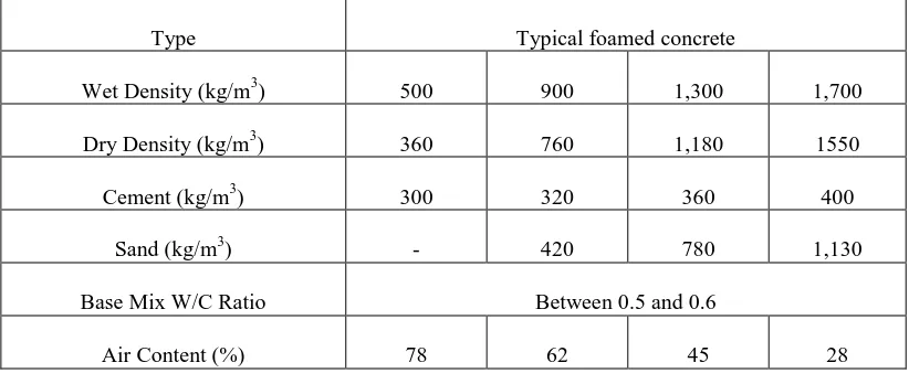
[image:32.595.120.531.279.448.2]partition, insulation and filling grades (Ramamurthy, Kunhanandan and Indu, 2009). According to BCA (1994), compressive strength of foamed concrete depends on the density, initial water to cement ratio and cement content. Density of foamed concrete can have an influence on the ultimate strength, particularly for the lower density foamed concrete. Uniformly sized small bubbles appear to produce higher ultimate strengths at all densities. Table 2.1 and 2.2 show the typical mixture details for foamed concrete and properties of foamed concrete.
Table 2.1: Typical mixture details for foamed concrete (BCA, 1994)
Type Typical foamed concrete
Wet Density (kg/m3) 500 900 1,300 1,700
Dry Density (kg/m3) 360 760 1,180 1550
Cement (kg/m3) 300 320 360 400
Sand (kg/m3) - 420 780 1,130
Base Mix W/C Ratio Between 0.5 and 0.6
Air Content (%) 78 62 45 28
Table 2.2: Typical properties of foamed concrete (BCA, 1994)
Dry Density (kg/m3)
Compressive Strength (MPa)
Thermal Conductivity
(W/mk)
Modulus of Elasticity
(Gpa)
Drying Shrinkage (%)
400 0.5-1.0 0.10 0.8-1.0 0.3-0.35
600 1.0-1.5 0.11 1.0-1.5 0.22-0.25
800 1.5-2.0 0.17-0.23 2.0-2.5 0.20-0.22
1,000 2.5-3.0 0.23-0.30 2.5-3.0 0.18-0.15
1,200 4.5-5.5 0.38-0.42 3.5-4.0 0.11-0.09
1,400 6.0-8.0 0.50-0.55 5.0-6.0 0.09-0.07
1,600 7.5-10.0 0.62-0.66 10.0-12.0 0.07-0.06
9
[image:33.595.132.509.241.511.2]concrete properties. Figure 2.1 shown the effects of coarse sand and fine sand on its compressive strength. For foamed concrete with dry density from 800kg/m3 to 1400kg/m3, the strength varies from 1 MPa to 10 MPa. The strength over density ratio had also been studied (Table 2.3 depicts the result). Their findings had good agreement with the foamed concrete strength listed by BCA (1994), and therefore the properties listed by BCA (1994) was still relevant to be used as a reference and design guide of the compressive strength and density of foamed concrete.
Figure 2.1: Strength density variation for mixes with sand of different fineness (Kunhanandan and Ramamurthy, 2006)
Table 2.3: Comparison of strength to density ratio (in MPa per kg/m3 x 1000) (Kunhanandan and Ramamurthy, 2006)
Design density, kg/m3
Strength to density ratios for foamed concrete mixes with
Coarse sand Fine sand Fine sand-fly ash Fly ash
1,000 0.77 1.73 1.68 2.79
1,250 3.87 3.63 5.32 7.11
1,500 5.04 6.94 8.64 12.66
Dry density, kg/m3
28
-D
ay c
ompr
essive
[image:33.595.122.514.640.763.2]10
2.2.2 Polystyrene foam
Polystyrene foam was used as a building insulation material because of its good thermal insulation and hyper elastic properties. Polystyrene foam is often used in insulating concrete forms, structural insulated panel building systems and non-weight bearing architectural structures. Polystyrene foam commonly used as building materials are expanded polystyrene foam (EPS) and extruded polystyrene foam (XPS) types.
According to Scheirs and Priddy (2003) EPS is used in many building projects for thermal insulation, sound proofing in new buildings or renovation work. EPS foam slabs are used for the insulation of walls, roofs, floors and ceilings. The polystyrene particles sizes range between 0.9 and 1.6 mm are preferably used for this application.
For the thermal insulation of walls, there is a difference between outside and inside wall and core insulation. For the outside wall insulation the EPS foam is put directly on the stone bearing structure. A fabric reinforced plastering or a ventilated facade protects it from the weather exposure. Using sandwich panels of EPS plasterboards, modern heat insulation standards can be achieved on the walls of older building. For core insulation, the insulation layer is in- between the bearing wall and the external weather resistant wall. Another system of insulation is the use of EPS moulded foam parts (insulated concrete forms) for a combination of outer and inner wall insulation. A wall is built with these moulded foam parts and filled with concrete.
Frankl et al. (2011) investigated the behaviour of precast, pre-stressed concrete sandwich wall panels reinforced with carbon-fibre-reinforced polymer (CFRP) shear grid. Six panels were designed and tested to evaluate their flexural reaction under combined vertical and lateral loads. The study included panels fabricated with two different insulation types: EPS insulation and XPS insulation.
11
2.2.2.1 Physical properties of expanded polystyrene
According to Texas Foam Inc (2011), the mechanical properties of expanded polystyrene depend largely upon density; in general, strength characteristics increase with density as tabulated in Table 2.4. The data only represents the typical value and testing data can be different from it with ± 10-15% from listed values.
[image:35.595.121.519.395.611.2]It is noted that compressive strengths listed in Table 2.4 are not ultimate values at either a yield or failure point because polystyrene is a hyper elastic material which yields under compressive loads (as illustrated in the typical stress/strain curves of Figure 2.2).Compressive strength values that are listed in Table 2.4 are at 10% deformation, a level often considered to be a minimum value for energy absorption under impact loadings.
Table 2.4: Typical properties of expanded polystyrene (Texas Foam Inc, 2011)
Density
Kg/m3
Stress at 10% Compression
(MPa)
Flexural Strength
(MPa)
Tensile Strength
(MPa)
Shear Strength
(MPa)
16 0.0896 0.1999 0.2137 0.2137
24 0.1654 0.2965 0.3516 0.3654
32 0.2068 0.3999 0.4275 0.4826
40 0.2896 0.5171 0.5102 0.6343
48 0.4413 0.6067 0.6067 0.8136
56 0.4619 0.7239 0.6757 0.9653
12
Figure 2.2: Typical stress/strain curves for expanded polystyrene (Texas Foam Inc, 2011)
2.2.3 Shear connectors and reinforcement
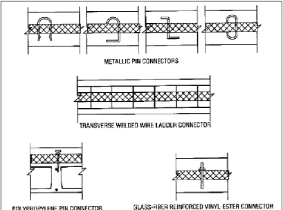
PCI committee (1997) had clearly explained the shear connector’s properties and its function in precast sandwich wall panels. Shear connectors were used to transfer forces between the two wythes. In some cases, shear connector can be used to transfer the weight of a non-structural wythe to the structural wythe.
Some shear connector is called one way shear connector; those connectors are stiff in one direction but flexible in the other. Other shear connectors are stiff in at least two perpendicular directions and will consequently transfer both longitudinal and transverse horizontal shears as shown in Figures 2.3, 2.4 and 2.5.
13
14
Figure 2.4: Two way shear connectors, stiff in at least two perpendicular directions. (PCI committee, 1997)
[image:38.595.114.524.415.718.2]15
2.2.4 Normal concrete capping
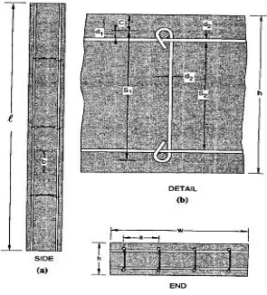
[image:39.595.121.520.235.410.2]Mohamad (2010) applied normal concrete capping at both ends on the PLFP panel with single shear connectors to distribute the load evenly. The normal concrete capping applied at both ends is to prevent the panel from premature cracking near loading and support areas. The design of capping is shown in Figure 2.6 and strengthened with horizontal and vertical steel bars of 9 mm diameter.
Figure 2.6: Normal concrete capping (Mohamad, Omar and Abdullah, 2011)
2.3 Accuracy of structural models
16
other structures normally have maximum errors on the order of less than 15% for the prediction of post cracking displacement and ultimate load carrying capacity of the structure.
2.3.1 Scaled model technique
Due to high costs and difficulty to do full scale experimental study for huge and complex structural problems, previous researchers studied many structures in smaller scale model. Sabnis et al. (1983) wrote a book as guidance for scaled model experimental study. Many researchers followed the scaling laws listed in their book and it was proven to work for full scale model (Knappett et al., 2011).
[image:40.595.131.508.503.649.2]Knappett et al. (2011) studied small scale modelling of reinforced concrete structural elements under bending loads at very high scale factors with application of scaling laws as shown in Table 2.5. Scaling laws was adopted from Harris and Sabnis (1999). Results proved that scaling technique allows for stiffness, strength and ductility of structural elements under bending loads to be simultaneously scaled and failure modes to be accurately reproduced.
Table 2.5: Scaling laws (Knappet et al., 2011)
Property Ratio* ( N = scale factor)
Stress, σ 1:1
Strain, ɛ 1:1
Young’s modulus 1:1
Length 1:N
17
[image:41.595.169.464.242.568.2]Gran et al. (1996) studied small scale experimental study with scale and ¼ scale sample. They studied the compression bending on the scaled reinforced concrete walls as shown in Figure 2.7. Axial compression combined with bending was used in the study. The repeatability of the results was excellent and the comparison between scales achieved good agreement. It was found that scale model is useful for checking analytical models for failure and post failure response.
Figure 2.7: Steel reinforcement for model wall sections (Gran et al., 1996)
18
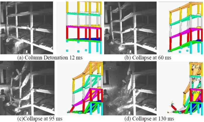
[image:42.595.219.421.217.370.2]collapse behaviour as seen in Figures 2.9 and 2.10. Tests results provided important validation to FEA. Small scale testing was therefore found to be practical and useful for studying the collapse phenomena by stages. Even though there are differences between full scale and small scale structures due to scaling effects and the practical challenges of manufacturing a small scale structure, simulation tools can effectively account for these scaling effects within the computational model.
Figure 2.8: Completed four storey reinforced concrete scale building (Vaughan et al., 2011)
Figure 2.9: Comparison of high speed camera images with equivalent snapshots from pretest simulation.
[image:42.595.144.493.442.650.2]19
Figure 2.10: Post failure photos of test article showing collapsed region compared with snapshot from pretest simulation showing collapsing section of model
(Vaughan et al., 2011)
2.4 Finite element analysis
Referring to Wahyu (2005), FEA is an analytical tool for predicting responses of certain engineering systems. The FEA in principle is a numerical approach for obtaining solutions. Its appeal lies in its use for predicting the field quantities of complicated structural shapes under general loading. It can also be easily used for structures with a large number of components. Its accuracy is bounded by all assumptions it takes and the inherent numerical error it carries.
At present, many conventional FEA software packages are available in the market such as: DIANA, ABAQUS, ADINA, OpenSees and ATENA. Their capabilities range from low to sophisticate with excellent graphic capabilities. In the application of finite element software, three terms are often used: pre-processor, solution process, and post processor.
Pre-processor: Process of geometric preparation, selection of elements, discretization of the domain, selection of materials, application of loadings, and the specification of the boundary conditions.
20
Post Processor: Process of representing the required analytical parameters. The user can evaluate the stress distribution, structural displacements, pressure distribution, or heat flux distribution. Some software programs can even produce a magnificent graphic representation in stunning colour.
2.4.1 Comparison of conventional FEA software
There are many conventional FEA software packages available in the market for various purpose of analysis. These software are designed for various types of analysis such loading study, dynamic study, thermodynamic, aerodynamic, impact loading study and also others analysis, and therefore a suitable software with adequate ability to analyse PLFP panel structural behaviour should be identified.
21
22
Table 2.7: Comparison of reinforcement response (Johnson, 2006)
2.4.2 Abaqus/Explicit versus Abaqus/Standard
ABAQUS software consists of two analysis products which are Abaqus/Standard and Abaqus/Explicit. Both products are capable of solving a wide variety of problems. (Abaqus, 2009).
Abaqus/Standard is a general-purpose analysis product that can solve traditional implicit finite element analysis for a wide range of linear and nonlinear problems involving the static, dynamic, thermal, and electrical response of components.
23
even forming a global stiffness matrix). Abaqus/Explicit is a special-purpose analysis product that uses an explicit dynamic finite element formulation. It is suitable for modelling brief, transient dynamic events, such as impact and blast problems, and is also very efficient for highly nonlinear problems involving changing contact conditions, such as forming simulations.
[image:47.595.114.533.359.664.2]The characteristics of implicit and explicit procedures determine which method is appropriate for a given problem. For those problems that can be solved with either method, the efficiency determined which product to use. The key differences for those two products is listed in Table 2.8 and used as guidance in choosing the suitable method for analysis.
Table 2.8: Key differences between Abaqus/Standard and Abaqus/Explicit. (Abaqus, 2009)
Quantity Abaqus/Standard Abaqus/Explicit
Element library
Offers an extensive element library. Offers an extensive library of elements well suited for explicit analyses. The elements available are a subset of those available in Abaqus/Standard.
Analysis procedures
General and linear perturbation procedures are available.
General procedures are available.
Material models
Offers a wide range of material models.
Similar to those available in
Abaqus/Standard; a notable difference is that failure material models are allowed.
Contact formulation
Has a robust capability for solving contact problems.
Has a robust contact functionality that readily solves even the most complex contact simulations.
Solution technique
Uses a stiffness-based solution technique that is unconditionally stable.
Uses an explicit integration solution technique that is conditionally stable.
Disk space and memory
Due to the large numbers of iterations possible in an increment, disk space and memory usage can be large.
Disk space and memory usage is typically much smaller than that for
24
2.4.2.1 Choosing between implicit and explicit analysis
In order to run analysis for finite element model efficiently, a suitable analysis method has to be chosen based on suitability and efficiency level. As briefed in the section before, Abaqus/Standard is more efficient for solving smooth nonlinear problems; on the other hand, Abaqus/Explicit is the clear choice for a wave propagation analysis. However, there are certain static or quasi-static problems that can be simulated well with either program.
Typically, these are problems which usually solved with Abaqus/Standard but may have difficulty converging due to contact or material complexities, resulting in a large number of iterations. Such analyses are expensive in Abaqus/Standard because every single iteration requires a large set of linear equations to be solved.
On the other hand, Abaqus/Explicit determines the solution without iterating by explicitly advancing the kinematic state from the previous increment. Even though a given analysis may require a large number of time increments using the explicit method, the analysis can be more efficient in Abaqus/Explicit if the same analysis in Abaqus/Standard requires much iteration. Another advantage of Abaqus/Explicit is that it requires much less disk space and memory than Abaqus/Standard for the same simulation. For problems in which the computational cost of the two programs may be comparable, the substantial disk space and memory savings of Abaqus/Explicit make it attractive (Abaqus, 2009).
2.4.3 Element types
REFERENCES
Abaqus 6.9 Documentation (2009). Dassault Systemes, Abaqus, Inc., United States Abdullah, R., Vidal, P. Paton-Cole, Samuel Easterling, W. F. (2007).
Quasi-static Analysis of Composite Slab. Malaysian Journal of Civil Engineering. 19(2). pp. 94-102
American Concrete Institute (1992). Building Code Requirements for Reinforced Concrete (ACI 318-89) and Commentary. Michigan: ACI 318-89. 1992 Artizabal-ochoa, J. D. (2012). Stability and Second order non-linear analysis of 2D
multi-column systems semi rigid connections: Effects of Initial Imperfections. International Journal of Non-linear Mechanics. 47(5). pp. 537-560
ASTM International (2010). Standard Test Methods for Static Modulus of Elasticity and Poisson’s Ratio of Concrete in Compression. West Conshohocken, PA: ASTM Standard C469/C469M-10.
ASTM International (2004). Standard Test Methods for Tensile Testing of Metallic Materials. West Conshohocken, PA: ASTM Standard E8M-04,
ASTM International (2005). Standard Test Methods for Conducting Strength Tests of Panels for Building Construction. West Conshohocken, PA: ASTM Standard E 72-10.
Benayoune, A (2003). Precast Concrete Sandwich Panel As A Building System. Ph.D. Thesis. Universiti Putra Malaysia.
Benayoune, A., Samad, A. A. A., Abang Ali, A. A. and Trikha, D. N. (2007). Response of pre-cast reinforced composite sandwich panels to axial loading. Construction and Building Materials 21. pp. 677-685
British Cement Association (1994). Foamed Concrete Composition and Properties. 165-168. British Cement Association.
179
British Standard Institution (1994). Eurocode 4: Design of composite steel concrete structures: Part 1.1. General Rules and Rules for Buildings,
DD ENV 1994-1-1, BSI London
British Standard Institution (2004). Eurocode 2: Design of Concrete Structures- Part 1-1 General Rules and rules for buildings. London: BS EN 1992-1-1 Boissonnade, N. and Somja, H. (2012). Influence of Imperfections in FEM Modeling
of Lateral Torsional Buckling. Proceeding of the Annual Stability Conference Structural Stability Research Council. Gravevine, Texas. pp. 1-15.
Construction Industry Development Board (CIDB) (2007). Construction Industry Master Plan Malaysia 2006-2015. Malaysia Construction Industry
Development Board
Eric, Q. S. (2006). Shear locking and hourglassing in MSC Nastran, ABAQUS and ANSYS. MSC Software Users Meeting.
Falade, F., Ikponmwosa, E. and Fapohunda, C. (2013). A Study on the Compressive and Tensile Strength of Foamed Concrete Containing Pulverized Bone as Partial Replacement of Cement, Pak. J. Engg. and Appl. Sci. Vol.13. pp. 82-93
Frankl, B. A., Lucier, G.W., Hassan, T. K., and Rizkalla, S. H. (2011). Behaviour of Precast, Prestressed Concrete Sandwich Wall Panels Reinforced With CFRP Shear Grid, PCI Journal,Spring. pp. 42-54.
Gran, J. K. and Senseny, P. E. (1996). Compression Bending of Scale Model Reinforced Concrete Walls. J. Eng. Mech. 122. pp. 660-668.
Harris, H. G. and Sabnis, G. M. (1999). Structural Modelling and Experimental techniques, 2nd Ed., Boca Raton, FL. CRC Press.
Hassan, T. and Rizkalla, S. (2010). Analysis and design guidelines of precast, prestressed concrete, sandwich wall panels reinforced with CFRP grid. PCI Journal, spring . pp. 147-162
Hazid, H. (2013, September 30). Affordable housing an on-going issue. The Edge. Retrieved from http://www.pr1ma.my
180
Jason. L., Cabot, G. P, Huerta. and Ghavamian. S. (2004). Damage and Plasticity for concrete behavior. European Congress on Computational Methods in Applied Sciences and Engineering, German. ECCOMAS. pp.1-16.
Jeung, H. D. (2002) Experimental and Theoretical Studies of Normal and High Strength Concrete Wall Panels. Ph.D Thesis. Griffith Univerisity.
Johnson, S. (2006). Comparison of Nonlinear Finite Element Modeling Tools for Structural Concrete. University of Illinois At Urbana Champaign. Retrieved October 7th 2013 at http://epfl.ch
Joshani, M., Koloor, S. S. R. and Abdullah, R. (2012). Damage Mechanic Model for Fracture Process of Steel Concreet Composite Slabs. Applied Mechanics and Materials Vol. 165, pp. 339-345
Kamar, K. A. M., Hamid, Z. A., Ghani, M. K., Egbu, C., and Arif, M. (2011). Collaboration Initiative on Green Construction and Sustainability through Industrialized Building Systems (IBS) in the Malaysian Construction Industry.International Journal of Sustainable Construction Engineering and Technology. pp.119-127
Knappett, J. A., Reid, C., Kinmond, S. and O’Reilly, K. (2011). Small-Scale Modelling of Reinforced Concrete Structural Elements for Use in a Geotechnical Centrifuge. Journal of Structural Engineering,137. pp. 1263-1271
Krispanarayan, K. M. (1977) Interesting aspect of the empirical wall design equation. ACI J Proc ;74(5). pp. 204-207
Kuddus, M. A. (2010). Numerical Simulation on Buckling Failure of the Masonry Load Bearing Walls. Advanced Masters in Structural Analysis of Monuments and Historical Construction. Technical University of Catalonia, Spain.
Kunhanandan Nambiar, E.K. and Ramamurthy, K. (2006). Influence of Filler type on The Properties of Foam Concrete. Cement and Concrete Composites, Vols. 28. pp. 475– 480
Lee, J. and Fenves, G. (1998). Plastic-Damage Model for Cyclic Loading of Concrete Structures. J. Eng. Mech., 124(8). pp. 892–900.
181
Liew, H. K. (2010) The Strain and Stress Distribution of Precast Lightweight Foamed Concrete Sandwich Panel under axial loading. Bsc, Thesis. Universiti Tun Hussein Onn Malaysia.
Macdonald, S. (2011). Research Paper: Supply and Demand in the Penang Housing Market: Assessing Affordability. Penang Institute
Mahbuba, B., Robert, G. D. and Alaa, E. E. (2007). Numerical Simulations of the Behaviour of Partially Encased Composite Columns. Canada: University of Alberta.
Malaysia Government (1996). Seventh Malaysia Pelan,Percetakan Nasional Berhad, Kuala Lumpur.
Mohamad, N., Omar, W. and Abdullah, R. (2011). Precast Lightweight Foamed Concrete Sandwich Panel (PLFP) Tested Under Axial Load: Preliminary Results. Advanced Materials Research. Vols. 250-253, pp. 1153-1162. Mohamad, N. and Mahdi, M. H. (2011).Testing of Precast Lightweight Foamed
Concrete Sandwich Panel With Single and Double Symmetrical Shear Truss Connectors Under Eccentric Loading. Advanced Materials Research. Vols. 335-336, pp. 1107-1116.
Mohamad, N. (2010). The Structural Behaviour of Precast Lightweight Foamed Concrete Sandwich Panels As Load Bearing Wall . Ph.D Thesis. Universiti Teknologi Malaysia.
Mokhatar, S. N. and Abdullah, R. (2012). Computational Analysis of Reinforced Concrete Slabs Subjected to Impact Loads. Int J. Of Integrated Engineering, Vol . 4 No. 2, pp. 70-76
Newberry, C. M., Hoemann, J. M., Bewick, B. T. and Davidson, J. S. (2010).
Simulation of Prestressed Concrete Sandwich Panels Subjected to Blast Loads. Structures Congress, Orlamdo, Florida.
Novoselac. S. , Ergic. T and Balicevic. P (2012). Linear and Nonlinear Buckling and Post Buckling Analysis of a Bar with The Influence of Imperfections. Tehnicki vjesnik 19 (3), pp. 695-701
Oberlender G. D. and Everard N. J. (1977). Investigation of Reinforced Concrete Wall Panels. ACI Journal Proceedings. Vols. 74(6), pp. 256-263.
182
Pillai S. U., and Partharasathy C. V. (1977). Ultimate Strength and Design of Concrete Walls. Journal of Building and Environment. 12, pp. 25-29.
Ramamurthy, K., Kunhanandan Nambiar, E. K. and Indu Siva Ranjani, G. A. (2009). Classification of Studies on Properties of Foamed Concrete .Cement and Concrete Composites, 3, pp. 388-396.
Robinson, G., Palmeri, A. and Austin, S. (2011) Implications of EC2 on the Design of Simply Supported Precast RC Panels under Eccentric Axial Load. Fib Syposium PRAGUE, pp. 1-9. ISBN 978-80-87158-29-6
Saheb, S.M. and Desayi, P. (1989). Ultimate Strength of RC Wall Panels in One Way In Plane Action. Journal of Structural Engineering, ASCE, Vol. 115(10), pp. 2617-2630.
Sabnis, G. M., Harris, H. G., White, R. N. and Mirza, M. S. (1983). Structural Modeling and Experimental Techniques. Englewood Cliffs:
Prentice-Hall, INC.
Scheirs, J. and Priddy, D. (2003). Modern Styrenic Polymers: Polystyrenes and Styrenic copolymers. Wiley Series in Polymer Science. The Atrium, Southern Gate, Chichester; John Wiley and Sons Ltd.
Shuid, S. (2004). Low Medium Cost Housing in Malaysia: Issues and Challenges, APNHR Conference, The University of Hong Kong.
Sultan Sidi, N. S. (2011). Syarahan Perdana 2011: The Different Scenarios of Housing Problem in Malaysia. Batu Pahat: Penerbit UTHM.
Sumadi, S. R. and Ramli, M. (2008). Development of Lightweight Ferrocement Sandwich Panels for Modular Housing and Industrialized Building System. Universiti Teknologi Malaysia: Research Vote No: 73311.
Texas Foam Inc (2011). Expanded Polystyrene (E.P.S) Handbook. Retrieved March 18, 2013 from p. 3 at http://www.texasfoam.com/EPS-Book.pdf
Vaughan, D., Milner, D. and Gran, K. (2011). New methods for progressive collapse testing and simulation. Structure Congress, pp. 2358-2369
Wahyu, K. (2005). An Introduction to the Finite Element Method. Singapore. McGraw-Hill Education (Asia).
183
Wright, H. (1998). The Axial Load Behaviour of Composite Walling. J. Construct. Steel Res. Vol.45, No. 3, pp. 353-375.