FORMULATING THE PLASTIC DEFORMATION
EXPRESSION ON COATED SUBSTRATE AS A COATING
SELECTION TOOL
Nagentrau s/o Muniandy
A thesis submitted in
fulfillment of the requirement for the award of the Degree of Masters
FACULTY OF MECHANICAL AND MANUFACTURING ENGINEERING UNIVERSITI TUN HUSSEIN ONN MALAYSIA
“To my parents, teachers and almighty God....”
To my beloved mother and father,
Mr. Mrs. Muniandy & Nookkaretnam
For being the backbone of my life by supporting me from the very beginning
To my supervisor and mentors,
A/Prof. Dr. Waluyo Adi Siswanto
Dr. Abdul Latif Mohd. Tobi
Prof. Dr. Mohd. Nasir Tamin
For their consistent encouragement, guidance and support throughout the
research
To my family and friends
For their trust, cooperation and motivation during this project
Acknowledgement
First and above all, I praise the Almighty God for blessings me the strength and capability to complete the research successfully. This thesis owes its presence to the motivation, support and assistance of several good souls. Therefore, I would like to express my sincere gratitude to all of them. My greatest appreciation goes to my parents, my siblings and relatives for their unconditional love, patience and been together through my thick and thin. With their genuine love and respect I wholeheartedly dedicate this thesis to my family.
I would like to express my deepest thanks to my supervisor Assoc. Prof. Dr. Waluyo Adi Siswanto, who has been a constant source of guidance and enthusiasm during my research. I greatly appreciate for his intellectual support and persistent encouragement throughout this research project and thesis writing. I am thankful for his flexible discussion time, precious suggestions and most importantly his trust on me which really boosted my effort towards completing the research.
A special thanks goes to my co-supervisor Dr. Abdul Latif Mohd. Tobi because without him, I would never been interested in this research. I am grateful for his financial assistance from setting up the research proposal until this research completed. I am also indebted to him because he moulded me into a good researcher. Particular gratitude goes to Prof. Dr. Mohd. Nasir Tamin from Universiti Teknologi Malaysia (UTM) for insightful ideas with his leading knowledge contribution. My endless thanks to him for his inspiration in order to accomplish this research and guiding me in journal writing.
I warmly thank all of my colleagues for their unflagging support and care during the research. Last but not least, I would never forget all the good hearted personalties that have been an indispensable impetus who contributed directly nor indirectly to the progress of my research and the thesis writing.
Abstract
This study presents the investigation of elastic coating performance responses on elastic-plastic substrate of advanced alloys using Finite Element (FE) method with an explicit numerical algorithm under quasi-static condition. Cylinder-on-flat contact configuration subjected to a normal and tangential loading is examined. Two aeroengine materials, namely Ti-6Al-4V and Super CMV (Cr-Mo-V) alloys are employed. Coating mechanical properties which are applied load (500 N − 1000 N), sliding displacement amplitude
(0.005 mm−0.12 mm), friction coefficient (0.3−0.9), coating elastic modulus
(100 GPa − 400 GPa) and coating thickness (0.01 mm − 0.1 mm) are
investigated. The effect of coating parameters on stress-strain distributions along with plastic deformation of the coated substrate are evaluated. The FE model is validated by comparing with theoretical Hertzian contact solution for homogeneous substrate, meanwhile coated substrate is validated by comparing with reported literature. The evolutions of contact pressure, von Mises stress, equivalent plastic strain, tangential stress and surface profile are examined for various coating parameters. There is a clear increasing trend of development in stress-strain distributions along with plastic deformation, maximum pile-up and depth-in values with the increase in all coating parameters for both coated substrates (except for coating thickness effect on Super CMV material, where the contradict trend is noted). Friction coefficient acts as the significant coating parameter that leads to plastic deformation failure of coated substrate. The relatively higher stiffness and yield strength of the coated Super CMV alloy registered limited plastic deformation compared to the coated Ti-6Al-4V alloy. The coated substrate plastic deformation mathematical expressions are formulated according to the Lagrange multivariate interpolation which can be used as an alternative method for FE approach. The weighted scoring method is practised in coating selection approach based on plastic deformation failure of coated substrate. The verified coating selection tool can contribute to knowledge in suitable material selection for coating based on its performance.
Abstrak
Kajian ini membentangkan pengaruh pelbagai paramater lapisan (coating) elastik pada substrat elastik-plastik di bawah keadaan kuasi-statik dengan menggunakan kaedah unsur terhingga (FEM). Konfigurasi silinder atas plat rata tertakluk kepada bebanan normal dan tangen dikaji. Dua jenis bahan aeroengine, iaitu aloi-aloi Ti-6Al-4V dan Super CMV (Cr-Mo-V) dikaji dalam analisis ini. Antara sifat mekanikal lapisan yang dikaji ialah beban digunakan (500 N − 1000 N), amplitud anjakan (0.005 mm − 0.12 mm), pekali geseran
(COF) (0.3−0.9), modulus elastik (100 GPa−400 GPa) dan ketebalan lapisan
0.01 mm − 0.1 mm). Kesan parameter lapisan pada tegasan-terikan bersama
Contents
Declaration ii
Dedication iii
Acknowledgement iv
Abstract v
Abstrak vi
List of Figures x
List of Tables xvii
List of Appendices xix
List of Symbols xix
Chapter 1 Introduction 1
1.1 Research Background 2
1.2 Problem Statement 4
1.3 Research Objectives 4
1.4 Research Scopes and Limitations 5
1.5 Research Significance 6
1.6 Thesis Organisation 7
Chapter 2 Literature Review 8
2.1 Contact mechanics 8
2.1.1 Tribology 9
2.1.2 Friction 9
2.1.3 Hertzian elastic contact 10
2.2 Stress-strain relations 11
2.3 Plasticity 16 2.3.1 Plastic deformation mechanism 17
2.3.2 Plasticity work hardening 20
2.4 Coating and Substrate 24
2.4.1 Tribological coating 25
2.4.2 Coating selection 26
2.5 Normal loading and tangential loading 27
2.6 Coating failure 29
2.6.1 Macromechanical friction and wear
mechanisms on coating surface 29
2.7 Finite element method (FEM) 30
2.7.1 Previous Finite element analysis of coated
substrate 30
2.8 Coated substrate plastic deformation 35 2.9 Multivariate Lagrange Interpolation 37
2.10 Weighted scoring method 40
2.11 Summary of literature review 41
Chapter 3 Methodology 42
3.1 Introduction 42
3.2 Research flow 42
3.3 Basic Assumptions 47
3.4 Finite element modelling 48
3.4.1 Finite element simulation software 48
3.4.2 Physical model 49
3.4.3 Model Geometry 50
3.4.4 Assigning the material 53
3.4.5 Finite element meshing 54
3.4.6 Contact interaction 56
3.4.7 Boundary condition and step configuration 57 3.5 Assessment parameters and method 61
3.5.1 Assessment parameters 61
3.5.2 Assessment methods 63
3.6 Analysis techniques 63
3.6.1 Output Data Base (ODB) file 64 3.6.2 Area under the curve for energy terms 67
3.6.3 Surface profile analysis 68
Chapter 4 Results and discussion 74
4.1 Introduction 74
4.2 Finite element model validation 75
4.2.1 Homogeneous substrate 75
4.2.2 Coated substrate 80
4.3 Evolution of internal energy terms 82
4.4 Coating Parameter study 84
4.4.1 Effect of contact Loading 84
4.4.2 Effect of sliding displacement amplitude 97 4.4.3 Effect of friction coefficient 109 4.4.4 Effect of coating elastic modulus 122 4.4.5 Effect of coating thickness 136
4.5 Surface profile 149
4.6 Plastic deformation mathematical expressions of
coated substrate 155
4.7 Coating selection 170
Chapter 5 Conclusion and recommendation 174
5.1 Conclusion 174
5.2 Knowledge contribution 176
5.3 Recommendation for future works 178
References 179
Vitae 200
List of Figures
Figure No Title Page
2.1 A frictional force,F is needed to cause motion rolling
and sliding (Ludema, 1996) 10
2.2 Hertzian non-conforming contact (Johnson &
Johnson, 1987) 11
2.3 Different material stress-strain response (Roesler
et al., 2007) 12
2.4 Elastic deformation stress-strain relationship
(Hibbeler, 2011) 13
2.5 Elastic-plastic deformation stress-strain relationship
(Hibbeler, 2011) 14
2.6 Stress-strain diagram for ductile material (steel)
(Hibbeler, 2011) 15
2.7 Relationship between shakedown behaviour and wear rate under repeated sliding condition (Fouvry et al.,
2001) 17
2.8 Deformation process by slip; (a) undeformed, (b) elastically deformed (c) elastically and plastically deformed, (d) plastically deformed (Lal & Reddy,
2009) 18
2.9 Most closely packed atoms in (a) ace-centred cubic, (b) hexagonal close packed and (c) body centred cubic
cell structures (Lal & Reddy, 2009) 19 2.10 Twinning process (Lal & Reddy, 2009) 19 2.11 Isotropic hardening yield surface (Rees, 2012) 21 2.12 Kinematic hardening yield surface (Rees, 2012) 22 2.13 Process of delamination wear mechanism (Tobiet al.,
[image:9.595.132.495.236.760.2]2.15 Tribological process of coated surface (Koutsomichalis
et al., 2009) 26
2.16 Typical coating applications in the mechanical
engineering field (Grzesik, 2003) 27
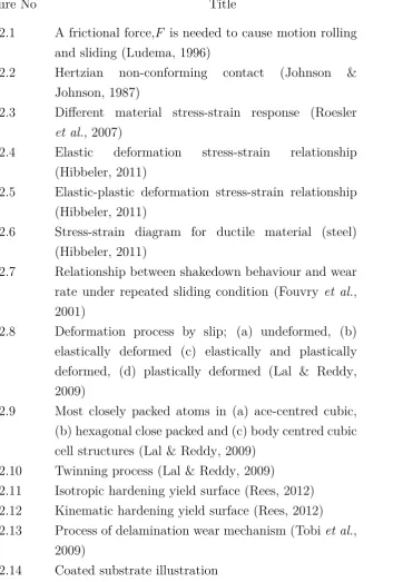
2.17 Normal pressure and tangential traction on contact
half-plane (Johnson & Johnson, 1987) 28 2.18 Macromechanical contact conditions for different
mechanisms which influence friction when a hard spherical slider moves on a coated flat surface
(Holmberg et al., 2006) 30
2.19 Schematic illustration of the scratch tester stylus drawn along the coated sample. The material loading and response can be divided into three phases: ploughing, interface sliding and pulling the
coating (Holmberg et al., 2006) 31
2.20 Schematic illustration of the three-dimensional finite
element mesh (Holmberg et al., 2006) 32 2.21 (a) Full model mesh, (b) contact region mesh detail
and (c) schematic view of the cylinder on flat coated
substrate model (Mohd Tobi et al., 2011) 33 2.22 Comparison of FE-predicted and experimental wear
profiles for coated SCMV pair for (a) 100,000 cycles, (b) 300,000 cycles, and (c) 600,000 cycles (Mohd Tobi
et al., 2011) 34
2.23 Model configuration (a) overall model layout and (b) mesh around the indentation contact in multilayer
coatings (Zhao et al., 2011) 35
2.24 Effect of deformation, yield and the cracks formation on the stress-strain curve obtained from spherical indentation of coated specimen. (1) elastic–plastic deformation; (2) plastic deformation; (3) fracture of
coating (Kot et al., 2013) 36
3.1 Overall research flowchart 43
3.2 Detailed flowchart of stage 1 : Coated substrate
parametric study 44
3.3 Detailed flowchart of stage 2 : Formulating coated
substrate plastic deformation mathematical expression 46
3.4 Detailed flowchart of stage 3 : Verifying coating
selection tool 47
3.5 Schematic of crossed cylinder-on-flat geometry used
for fretting tests 50
3.6 Schematic view of the half cylinder-on-flat coated
substrate contact configuration 52
3.7 Assembly of half cylinder and flat plate 52 3.8 Plastic stress-strain curves for Ti-6Al-4V and SCMV
(Benedetti & Fontanari, 2004; Leen et al., 2001) 54 3.9 Variations of the predicted maximum contact pressure
with element size 55
3.10 Mesh module of the 2D contact model 56
3.11 Master and slave surfaces interaction 57 3.12 Contact property of the coated substrate 57 3.13 Initial step - applying boundary condition 59
3.14 Step 1 - Applying the load 59
3.15 Step 2 - Applying the displacement 60
3.16 Step 3 - Unloading 60
3.17 Abaqus coated substrate simulation ODB file 65 3.18 Analysis techniques to extract FE predicted results 65 3.19 FE result extraction from specific element from ODB
field output 66
3.20 FE result extraction using path line technique 66 3.21 Initial and final contact point position 67
3.22 Diagram illustrating Simpson’s rule 68
3.23 Schematic diagram of surface deformation occurred on
elastically coated elastic-plastic substrate 69 3.24 Coated substrates material weightage breakdown 71 3.25 Coated substrate parameter weightage breakdown 72
4.1 Contact pressure and contact half-width length comparison between FEM analysis and Hertzian
contact theoretical solution for Ti-6Al-4V 77 4.2 Contact pressure and contact half-width length
comparison between FEM analysis and Hertzian
contact theoretical solution for Super CMV 78 4.3 Sub-surface stress along Y-axis comparison between
4.4 Sub-surface stress along Y-axis comparison between FEM analysis and Hertzian contact theoretical
solution for Super CMV material 79
4.5 FE predicted tangential stress distributions comparison between FEM analysis and previous
study for coated Ti-6Al-4V substrate 81 4.6 FE predicted tangential stress distributions
comparison between FEM analysis and previous
study for coated Super CMV substrate 82 4.7 Evolution of internal and kinetic energy of the coated
substrate system 84
4.8 Contact pressure distribution of different contact
loading condition 86
4.9 Von Mises stress history of different contact loading condition 89 4.10 Equivalent plastic strain history of different contact
loading condition 91
4.11 Equivalent plastic strain after complete unloading for
500 N contact loading 93
4.12 Equivalent plastic strain after complete unloading for
750 N contact loading 94
4.13 Equivalent plastic strain after complete unloading for
1000 N contact loading 95
4.14 Tangential stress distribution of different contact loading 96 4.15 Contact pressure distribution of different sliding
displacement amplitude 98
4.16 Von Mises stress history of different sliding
displacement amplitude 101
4.17 Equivalent plastic strain history of different sliding
displacement amplitude 103
4.18 Equivalent plastic strain after complete unloading for
0.005 mm sliding displacement amplitude 105 4.19 Equivalent plastic strain after complete unloading for
0.05 mm sliding displacement amplitude 106 4.20 Equivalent plastic strain after complete unloading for
0.12 mm sliding displacement amplitude 107 4.21 Tangential stress distribution of different sliding
displacement amplitude 109
4.22 Contact pressure distribution of different friction coefficient 111 4.23 Von Mises stress history of different friction coefficient 114
4.24 Equivalent plastic strain history of different friction coefficient 116 4.25 Equivalent plastic strain after complete unloading for
friction coefficient of 0.3 118
4.26 Equivalent plastic strain after complete unloading for
friction coefficient of 0.6 119
4.27 Equivalent plastic strain after complete unloading for
friction coefficient of 0.9 120
4.28 Tangential stress distribution of different friction coefficient 122 4.29 Contact pressure distribution of different coating
elastic modulus 125
4.30 Von Mises stress history of different coating elastic modulus 128 4.31 Equivalent plastic strain history of different coating
elastic modulus 130
4.32 Equivalent plastic strain after complete unloading for
coating elastic modulus of 100 MPa 132 4.33 Equivalent plastic strain after complete unloading for
coating elastic modulus of 200 MPa 133 4.34 Equivalent plastic strain after complete unloading for
coating elastic modulus of 400 MPa 134 4.35 Tangential stress distribution of different coating
elastic modulus 136
4.36 Contact pressure distribution of different coating thickness 138 4.37 Von Mises stress history of different coating thickness 141 4.38 Equivalent plastic strain history of different coating thickness 143 4.39 Equivalent plastic strain after complete unloading for
coating thickness of 0.01 mm 145
4.40 Equivalent plastic strain after complete unloading for
coating thickness of 0.05 mm 146
4.41 Equivalent plastic strain after complete unloading for
coating thickness of 0.1 mm 147
4.42 Tangential stress distribution of different coating thickness 149 4.43 Surface profiles of the coated substrates upon
complete unloading under different load 150 4.44 Surface profiles of the coated substrates upon
complete unloading under different sliding
displacement amplitude 151
4.45 Surface profiles of the coated substrates upon
4.46 Surface profiles of the coated substrates upon
complete unloading under different coating elastic modulus. 152 4.47 Surface profiles of the coated substrates upon
complete unloading under different coating thickness 152 4.48 Decimal digits truncation effect on mathematical
expression accuracy 157
4.49 Equivalent plastic strain curve of Ti-6Al-4V as a
function of time and loading 160
4.50 Equivalent plastic strain curve of SCMV as a function
of time and loading 161
4.51 Equivalent plastic strain curve of Ti-6Al-4V as a
function of time and sliding displacement 162 4.52 Equivalent plastic strain curve of SCMV as a function
of time and sliding displacement 163
4.53 Equivalent plastic strain curve of Ti-6Al-4V as a
function of time and friction coefficient 164 4.54 Equivalent plastic strain curve of SCMV as a function
of time and friction coefficient 165
4.55 Equivalent plastic strain curve of Ti-6Al-4V as a
function of time and coating elastic modulus 166 4.56 Equivalent plastic strain curve of SCMV as a function
of time and coating elastic modulus 167 4.57 Equivalent plastic strain curve of Ti-6Al-4V as a
function of time and coating thickness 168 4.58 Equivalent plastic strain curve of SCMV as a function
of time and coating thickness 169
A.1 Tangential stress contour during loading 191 A.2 Normal stress contour during loading 192
A.3 Shear stress contour during loading 192
A.4 Tangential stress contour during sliding 193 A.5 Normal stress contour during sliding 193
A.6 Shear stress contour during sliding 194
A.7 Tangential stress contour during unloading 194 A.8 Normal stress contour during unloading 195 A.9 Shear stress contour during unloading 195 B.1 Surface spatial displacement at elemental nodes
during loading (Step-1), sliding (Step-2) and
unloading (Step-3) for Ti-6Al-4V 196
B.2 Surface spatial displacement at elemental nodes during loading (Step-1), sliding (Step-2) and
List of Tables
Table No Title Page
3.1 Materials properties of coated substrate 54
3.2 Smooth step amplitude for analysis 61
3.3 Different coated substrate configuration models 62
3.4 Coated substrates material weightage 71
3.5 Coated substrate parameter weightage 72
4.1 Validation of homogenous substrate FE model 78 4.2 Validation of coated substrate FE model 81 4.3 Internal and kinetic energy of the coated substrate system 84 4.4 Maximum contact pressure of different contact
loading condition 87
4.5 Contact half-width length of different contact loading
condition 87
4.6 Maximum von Mises stress of different contact loading
condition 89
4.7 Maximum equivalent plastic strain of different contact
loading condition 91
4.8 Maximum contact pressure of different sliding
displacement amplitude 99
4.9 Contact half-width length of different sliding
displacement amplitude 99
4.10 Maximum von Mises stress of different sliding
displacement amplitude 101
4.11 Maximum equivalent plastic strain of different sliding
displacement amplitude 104
4.12 Maximum contact pressure of different friction coefficient 112 4.13 Contact half-width length of different friction coefficient 112 4.14 Maximum von Mises stress of different friction coefficient 114
4.15 Maximum equivalent plastic strain of different friction
coefficient 116
4.16 Maximum contact pressure of different coating elastic
modulus 125
4.17 Contact half-width length of different coating elastic modulus 126 4.18 Maximum von Mises stress of different coating elastic
modulus 128
4.19 Maximum equivalent plastic strain of different coating
elastic modulus 131
4.20 Maximum contact pressure of different coating thickness 139 4.21 Contact half-width length of different coating thickness 139 4.22 Maximum von Mises stress of different coating thickness 141 4.23 Maximum equivalent plastic strain of different coating
thickness 143
4.24 Maximum pile-up and depth-in of the coated
substrates according to different parameters 154 4.25 Mathematical expression truncation with different
decimal digits 157
4.26 Coated substrate plastic deformation mathematical expressions for different coating parameters
according to the substrate material. 159 4.27 Coating selection table considering plastic
deformation of coated substrate 171
List of Appendices
Appendix Title Page
A Stress components comparison of coated substrate 191 B Surface spatial displacement at elemental nodes
during simulation 196
C Matlab script file for mathematical expression 198
List of Symbols
α Dundurs parameters on elastic mismatch
β Dundurs parameters on Poisson’s ratio difference
δ Sliding amplitude
µ Friction coefficient
ρ Density
σf Fracture stress
σpl Proportional limit
σu Ultimate stress
σy Yield stress
εe Elastic strain
εp Plastic strain
εx Total deformation
A Distance along the first line
a Contact half-width length
B Distance along the middle line
C Distance along the last line
c Coating
E Elastic modulus
h Distance betwen each line
P Normal load
p(x) Contact pressure distribution
R Radius
s Substrate
t Time
v Poisson ratio
2D Two-dimensional 3D Three-dimensional AS Aggregate score COF Coefficient of friction CPRESS Contact pressure FE Finite Element
FEM Finite Element Method GPa Giga Pascal
LSMB Lower Specimen Mounting Block
LVDT Linear Variable Displacement Transducer MISES Von Mises stress
mm Milli Meter MPa Mega Pascal
N Newton
ODB Output Data Base PEEQ Equivalent plastic strain PW Parameter weightage
S Score
S11 Tangential stress
SCMV Super Chromium Molybdenum Vanadium alloy SW Substrate weightage
Ti-6Al-4V Titanium alloy
U Spatial displacement at nodes USMB Upper Specimen Mounting Block
Chapter 1
Introduction
Contact mechanics is concerned as the study of solid deformation when two bodies (surfaces) are touching and interacting with each other at one or more points. Mechanics of contact is deliberated as an essential subject because most of the engineering applications deal with it consequently. Contact mechanics offers an interesting, yet challenging research subject as it can lead to failure effect on contacting materials such as plastic deformation, fracture, fatigue, wear and others. Obviously, the contact failure can be significant and able to develop under corrosive, erosive, high temperature and heavy contact environment.
In the recent decades, minimizing contact failure on contacting bodies is considered to be a major concern, especially in safety engineering as contact mechanics failure can result in costly flaws and fatality. So, the knowledge in protecting contacting bodies from failure is very crucial, thus advances in reducing contact mechanics failure need to be studied extensively. One of the most competent approach to protect contact engineering components is by coating application. A coating can be defined as a covering that is applied on the surface of a body which referred as the substrate. Coating widely used for decorative, functional or both purposes.
2
the major economic loss by protecting contacting components from any failure.
1.1 Research Background
Recent developments of coating application in contact mechanics have led to a renewed interest in coating selection. In addition, coatings are generally used to provide protection for surfaces that subjected to contact loading, i.e. piston rings, bearings, machine tools, cams and followers (Oliveira & Bower, 1996). Coating approach is practised in order to alter the surface properties of a substrate such as wettability, wear resistance, adhesion or corrosion resistance. For instance, thermal barrier coating is applied in gas turbine engines to guard components from thermal shock; hard and corrosion resistant coatings are applied on machining and drilling tools to protect the components from friction, wear and fretting damage; in medical devices or implants coating offers wear resistance, chemical durability and biocompatibility (Demidova et al., 2012).
Failure of the coating or substrate is a major concern in coated engineering applications. Obviously, the deterioration of coated substrate can be associated with the failure of coating itself or the substrate deformation (Mohd Tobi et al., 2013). It appears from the aforementioned studies that most attention has been paid to contact mechanics of different coating/substrate composites (Komvopoulos, 1989; Gupta & Walowit, 1974; Weppelmann & Swain, 1996). Hard elastic coatings are suitable solutions to enhance surface performance and improving endurance life of contact components. Most hard coatings are made up of ceramic compounds such as nitrides, carbides, cermets, ceramic alloys and metastable materials like cubic boron nitride and diamond.
3
Michler & Blank (2001) studied the coating fracture and substrate plasticity induced by the spherical indenter; their analysis revealed that the initial damage of coated substrate system is noticed to occur by plastic deformation of substrate or below the interface. This is consistent with the experimental and numerical study on spherical indentations of coating-substrate system demonstrated by Kot et al. (2013), which showed that coated substrate damage initiated as substrate elastic-plastic deformation followed by plastic deformation and finally fracture of coating.
Titanium alloy (Ti-6Al-4V) and high strength steel Super CMV (Cr-Mo-V) are the materials which show high interest on coating utilization due to their wide application in various field. Interestingly, Ti-6Al-4V and Super CMV alloys had been investigated by several researchers because of their high strength, ductility, excellent corrosion and fatigue resistance characteristics along with their extensive application in aeroengines and gas turbines (Ford, 1997; McColl et al., 2004; Tobi et al., 2009; Hyde, 2002). Besides that, coating utilization on Ti-6Al-4V and Super CMV alloys is necessary as both are aeroengine specific materials where potentially can experience contact damages such as in the spline coupling (Leenet al., 2002) and the dovetail fan blade joint (Ciavarella & Demelio, 2001; Rajasekaran & Nowell, 2006).
So, appropriate surface coating selection will be able to contribute on improving reliability and lifetime of these contact components. Previous studies have been primarily concentrated on coating failures such as coating brittle fracture, through thickness cracking, spallation, delamination coating buckling and others (Bull & G-Berasetegui, 2006; Bull, 1991; Mohd Tobi et al., 2013). However, studies related to substrate failure are relatively scanty and there has been limited investigation on substrate plastic deformation. In addition, substrate plastic deformation occurs before any other failure triggers in coated substrate system (Zheng & Sridhar, 2006).
4
1.2 Problem Statement
Generally, the awareness on the contacting components safety design and its protection is a concern in minimizing costly flaws and human safety in various engineering field. It may however be noted that rigorous study can be done to reduce potential danger of coated contact components failure due to plastic deformation of the substrate. In the future, coating need to be designed in order to withstand substrate plastic deformation. It should be noted that there is still shortage of systematic studies on the effect of mechanical properties of coating on substrate plasticity.
Substrate plastic deformation failure should get an insight as the initial coated substrate system failure maps occur by substrate yield (Michler & Blank, 2001). Sooner or later, the substrate plastic deformation will cause failure on the coating surface which acts as first line of defence for a coated substrate system (Kot et al., 2013). In addition, coating selection based on substrate yield for specific applications is a complicated task due to many factors such as applied external load, sliding displacement amplitude, contact friction coefficient coating material and thickness should be taken into consideration.
For time being, most of the coating selection with the aim of minimising substrate plasticity is done by trial and error basis which might lead to costly flaws and degrade the sustainability of the industry. In particular, Finite Element approach should be practised in predicting substrate plastic deformation which will aid in coating selection as this method is an effective tool in determining stress-strain field in coated substrate system. Besides that, the understanding on coating selection and purpose should be polished as lack of fundamental understanding in term of coated substrate mechanics analysis. Furthermore, a comprehensive guide for coating design based on the plastic deformation of Ti-6Al-4V and Super CMV alloys has not yet been established.
Hence, protecting these materials from plasticity by proper coating selection often necessary because of their wide application in engineering fields, i.e. aeroengine specific, armour plating, spacecraft, naval ships, missiles, high performance automotive parts, medical devices and industrial machines.
1.3 Research Objectives
The purpose of this research are as follows :
5
modulus of coating and coating thickness on stress-strain distributions along with plastic deformation response of coated substrate subjected to contact loading.
(b) To formulate mathematical expressions based on numerical plastic strain results of coated substrate system verified in numerical problem cases.
(c) To verify an effective coating selection tool based on the substrate plastic deformation.
1.4 Research Scopes and Limitations
The scopes and limitations of the study are designed to achieve the goals of the research. Hence, the scopes and limitations for this research are as follows :
(a) Modelling two dimensional (2D) cylinder-on-flat contact configurations using coated aeroengine specific materials made of Titanium alloy (Ti-6Al-4V) and high strength steel Super CMV (Cr-Mo-V).
(b) Studying concerned variables of different coating mechanical properties, i.e. applied external load, sliding displacement amplitude, contact friction coefficient, coating material and thickness and their influence on stress-strain behaviour along with plastic deformation of the coated substrate..
(c) Modelling perfectly bonded elastic coating on elastic-plastic substrate subjected to contact loading with three steps, i.e loading, sliding and unloading without any slippage and delamination occur at the interface region.
(d) Fracture mechanics concept is not implemented as the coating assumed to withstand higher compressive and tensile forces.
(e) Coating debonding due to unloading, thermal stress and strain rate effects are not considered in this particular study.
(f) Formulating plastic deformation mathematical expressions based on numerical plastic strain results by using multivariate variable technique.
6
1.5 Research Significance
The contribution of this study is obvious as the resulting outcomes can be capitalized as guidelines to evaluate contacting coated substrate mechanics and the failure associated by substrate plastic deformation thorough the implementation of numerical analysis. The uniqueness of this research will be an advancement in the fundamental understanding of coating selection based on substrate yielding in engineering applications. In addition, the long term implications of this study will benefit multi-billion industries which deals with hard elastic coating usage on ductile substrate by proper coating selection to protect materials from plastic deformation, thus sustainability of the industry is guaranteed.
Since there has been a significant rise on aerospace industry all over the world, this study will lend a hand in the growth of technology in aerospace industry. Besides that, Malaysian government has planned to invest RM177
million by year 2020 in local aerospace company named Strand Aerospace Malaysia Sdn. Bhd. under the Economic Transformation Plan in order to improve human capital for High Value Engineering Services. So, the findings of this study will improve performances and reducing maintenance cost of aeroengine components via proper coating selection as aeroengine specific materials i.e. Ti-6Al-4V and Super CMV alloys are focused in this particular research. In addition, the benefaction of this study to our knowledge is not only in addressing the view point in academics but also assist in nation economic development especially, Human Capital Development in infrastructure.
The current research will contribute to our knowledge by addressing three important issues as follows :
(a) The influence of coating mechanical properties on stress-strain distributions along with plastic deformation response of coated substrate can be studied in detail. Thus, any failure associated by coated substrate plastic deformation can be prevented and life time of coated contacting components prolonged.
(b) Verified mathematical expressions according to Multivariate lagrange interpolation concerning coating parameters and substrate materials. These mathematical expressions can be used to predict equivalent plastic strain of coated substrates with high accuracy results without requiring any expensive computational time.
7
guideline for proper coating selection by comparing and identifying suitable coating according to substrate material and working conditions.
1.6 Thesis Organisation
The outline of thesis is given below :
Chapter 1 contains the research background, problem statement, objectives,
scopes and significance of the research. In addition, a brief introduction is given by addressing the motivation and importance of the study.
Chapter 2 reviews pertinent literatures on the understanding of stress-strain,
plastic deformation mechanism, finite element analysis, coating-substrate failure and coating selection in the study of coated substrate plastic deformation prediction for coating selection tool.
Chapter 3 outlines the numerical methodology using explicit finite element
approach pursued with different mechanical coating properties. The approach of formulating mathematical expressions and verifying coating selection tool is focussed.
Chapter 4 provides verification and validation of numerical model with
analytical solution and previous research results. The numerical result of stress-strain distributions along with plastic deformation of coated substrate is studied in detail. The mathematical expressions based on numerical plastic strain results of coated substrate system are formulated based on Lagrange multivariate interpolation and an effective coating selection tool is verified using weighted scoring method.
Chapter 5 offers the conclusions for this particular work. The recommendation
Chapter 2
Literature Review
2.1 Contact mechanics
The study of solid deformation where it touches each other at one or more than one points is referred as contact mechanics. A contact is said to be occurred if:
• Mechanical interaction of bodies along surfaces
• Surfaces should “touch”
• Occurrence of force pressing two bodies
• Contact area rely on materials, forces, temperature and geometry.
Generally, contact concern both elastic and plastic strain ranges beneath asperities (Ludema, 1996). Contact mechanics also distinguish between conforming and non-conforming contacts. When the surfaces of two bodies fit closely without deformation, then the contact is said to be conforming, while bodies which have contradictory profiles are considered to be non-conforming (Johnson & Johnson, 1987). Virtually, each and every movement in this planet related with contact and friction such as running, walking, driving cars or streaming of trains (Wriggers & Laursen, 2006). The base aspects that taken into account in the contact mechanics topic are normal direction, frictional stress acting tangentially between surfaces and the adhesion or pressure which acting perpendicularly to the contacting body surfaces.
9
information for the safe and energy efficient design of technical system for tribology study. The area of interest in contact mechanics are normal contact of elastic and inelastic solids, tangential loading and sliding contact, rolling contact of elastic and inelastic bodies, calendering and lubrication, dynamic effects and impact, thermoelastic contact and rough surface contact.
2.1.1 Tribology
Tribology is defined as science and engineering of contacting surfaces in relative motion. It comprises the study and application of the fundamental of friction, lubrication and wear. Tribology is the ’Ology’ or science of ’Triben’ where the word is originated from the Greek root known as ’Tribulation’. A direct translation defines Tribology as the study of rubbing and sliding. The modern and expanded meaning of tribology known as the study of friction, lubrication and wear (Ludema, 1996). In addition, tribology is a crucial aspect as the movement of one solid surface on another is fundamentally essential to the operation of many mechanisms such as natural and artificial (Hutchings, 1992). Tribology research and development benefit mankind in many ways such as quality, raw material savings, economical savings, energy savings, environmental and health factors.
For instance, in automotive industries the minimization in the mechanical losses because of effective tribology around 10 % could reduce the fuel consumption as 1.5 % equivalent to 340 litre of petrol during the lifetime of
the car (Tzanakis et al., 2012). Obviously, tribology plays a pivotal role in manufacturing to analyse and solve the costly flaws due to friction and wear in industries.
2.1.2 Friction
10
• friction force is independent of the apparent contact area
• friction force is independent of the sliding velocity
Amontons equation states that frictional force described as F = µW where
static friction or kinetic friction coefficient is stated as µ while the normal load
as W (Bhushan & Gupta, 1991). Frictional contacts can be classified into few
classes such as force transmitting components, energy absorption-controlling components, quality control components and low friction components (Ludema, 1996).
Figure 2.1: A frictional force,F is needed to cause motion rolling and sliding
(Ludema, 1996)
2.1.3 Hertzian elastic contact
There are two types of Hertzian elastic contact, i.e. conforming contact and non-conforming contact. Conforming contact is considered as a contact where two mating bodies touch exactly each other without any deformation (Johnson & Johnson, 1987). Journal bearing and a flat slider bearing are the examples of conforming contacts. Meanwhile, two bodies with various profiles are said to be non-conforming. When two non-conforming solids are in contact, the occurrence of deformation around their initial point of contact under the existence of load is takes place (Johnson & Johnson, 1987). A theory of contact is necessary to forecast the shape of contacting area and how it will transform if the applied load is rising. There are some assumptions in the Hertzian theory to formulate the calculation is valid. This particular type of contact is well displayed in Figure 2.2. The assumptions are as follows:
• The surfaces are continuous and non-conforming: a ≤R
11
• The surfaces are friction free: qx=qy = 0
• Each solid can be considered as an elastic half-space: a ≤ R1,2, a ≤ l
Where the major dimension of the contact area, R is the relative radius of
curvature and l is the significant of the bodies both literally and in depth.
Figure 2.2: Hertzian non-conforming contact (Johnson & Johnson, 1987)
2.2 Stress-strain relations
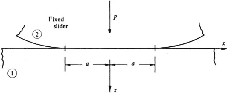
[image:31.595.129.514.189.351.2]12
Figure 2.3: Different material stress-strain response (Roesler et al., 2007)
Studies have found that a material can exhibit two types of of deformation such as elastic and plastic deformation respectively. Elastic deformation can be defined as the recovering of a loaded material to its original state upon complete unloading and the stress and strain are directly proportional to each other (Gurtin, 1973; Hibbeler, 2011). Figure 2.4 illustrates the stress-strain relation during elastic deformation. The stress-strain growth shows a linear trend which known as linear elastic deformation. Eq. (2.1) is used to calculate the elastic modulus, E of a material based on the stress-strain
curve. The elastic modulus, E corresponds to the particular proportionality
constant between stress and strain. The elastic modulus, E is obtained from the
slope of the elastic deformation linear curve.
E = σ ε =
σb−σa
[image:32.595.134.506.86.242.2]13
Figure 2.4: Elastic deformation stress-strain relationship (Hibbeler, 2011)
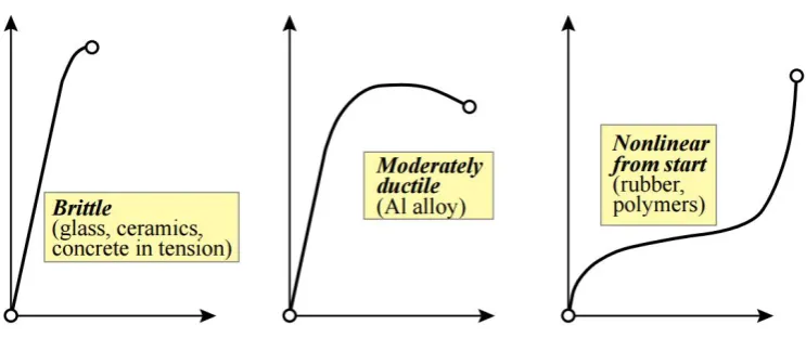
Meanwhile, the plastic deformation is different from the elastic deformation where the loaded material does not recover to the initial position upon complete unloading (Prevost, 1985; Hibbeler, 2011). This leads to the deformation is permanent. The initiation of plastic strain can lead to large deformation when small amount of stress is induced and this will cause further yielding until the material failure. The point where permanent deformation begins to occur known as Yield stress, σy. Figure 2.5 demonstrates the response
of stress-strain during elastic-plastic deformation. It is noted that plastic strain,
εp is significant than the elastic strain, εe. The total deformation of a material,
εx is the resultant of the plastic strain, εp and elastic strain,εe.
Eq. (2.2) presents the stress-strain curve in terms of the Ramberg-Osgood expression. Eq. (2.2) is originally developed for non-linear metals which encounter yielding and plastic strain. It involves the initial Young’s modulus(E0), the proof
stress (σp) corresponding to the plastic strain (p) and (n) which determines the
strain hardening of the stress-strain curve.
ε = σ E0 +p
σ σ
!n
[image:33.595.139.491.95.359.2]14
Figure 2.5: Elastic-plastic deformation stress-strain relationship (Hibbeler, 2011)
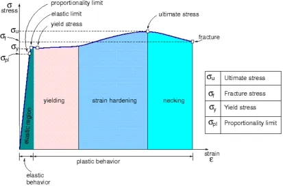
Numerous studies have attempted to explain the stress-strain behaviour of ductile materials (Dieter & Bacon, 1986; Hibbeler, 2011). Figure 2.6 presents the stress-strain diagram for ductile material especially steel. Based on the Figure 2.6, it is noted that there are 4 types of region in a stress-strain diagram for ductile material, namely elastic region, yielding region, strain hardening region and necking region. The material behaves differently depending on the induced strain amount. In addition, the composition of the material, loading rate, temperature, microscopic imperfection and test time affect the stress-strain behaviour of a material (Hibbeler, 2011; Kienzler & Herrmann, 2012).
Elastic behaviour of the material is occur at the elastic region as shown in Figure 2.6. The behaviour of this particular region is consistent with the Figure 2.4 as discussed earlier. In this region, the stress is proportional to the strain and the material is said to be linear elastic. The proportional limit, σpl is
[image:34.595.139.504.83.412.2]15
particular point, the material tend to return to its initial shape upon complete unloading. In fact, elastic limit rarely determined for steel since it is very close to the proportional limit, σpl and very difficult to detect (Hibbeler, 2011; Kienzler
& Herrmann, 2012).
A slight advancement in stress which exceeds the elastic limit will lead to material breakdown and permanent deformation; such a behaviour is called as material yielding which lead to plastic deformation. Yield stress or yield point,σy
is the critical stress that causes material yielding. The material will continuously elongate (strain) without any increment in load as exhibited in Figure 2.6 and this state often referred as perfectly plastic (Hibbeler, 2011; Kienzler & Herrmann, 2012).
Once the material achieved complete yielding, then an increment in load can be withstand by that particular material. This is mainly due to curve that increases continuously until reach the the maximum stress known as the ultimate stress, σu. The increment in such a manner is referred as strain hardening as
depicted in Figure 2.6 (Hibbeler, 2011; Kienzler & Herrmann, 2012).
Last but not least, the necking region is where the material elongates as the stress exceeds the ultimate stress,σu. In deed, such a case will result in decreasing
[image:35.595.113.527.472.744.2]16
2.3 Plasticity
Plasticity can be defined as deformation of a material which undergoing permanent change or non-reversible response due to applied force. Most of the real materials will experience some permanent deformation, which non-reversible after elimination of the load or force. Normally, major permanent deformations happen when stress achieves some critical value, known as yield stress which is a material property. Classical theory of plasticity states that initially materials deform elastically and deform plastically when reaching the yield stress. Perfect plasticity can occur as material undergo an irreversible deformation without any increment in stress due to load.
17
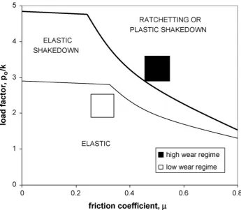
Figure 2.7: Relationship between shakedown behaviour and wear rate under repeated sliding condition (Fouvry et al., 2001)
2.3.1 Plastic deformation mechanism
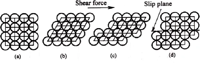
There are two noticeable mechanism of plastic deformation such as slip and twinning. Slip considered as prominent mechanism of plastic deformation in metal. The blocks of crystal slide over each other along the definite crystallographic planes which named as slip planes. It is compulsory that large scale of slipping of adjacent atomic plane (more than half atomic spacing) must occur to cause plastic deformation. It is equivalent to a deck of cards pushed from one end as slip happens when applied shear stress greater than a critical value.
[image:37.595.146.492.69.370.2]18
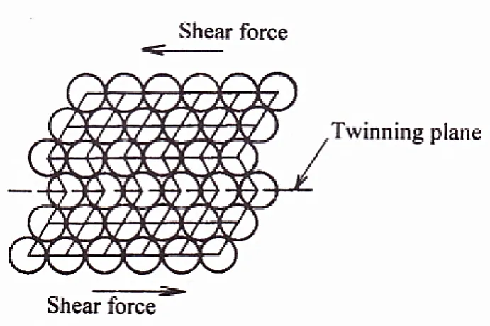
Twinning can be termed as a portion of crystal follows an orientation which is related to the orientation of remaining untwinned lattice in a definite, symmetrical way. The twinned part of the crystal can be considered as reflective (mirror) image of parent crystal. The symmetry plane is known as twinning plane. The chief role of twinning in plastic deformation is it acts as a root in changing the plane orientation to cause advancement in slip. Figure 2.10 illustrates twinning process results in atoms dislocation (Lal & Reddy, 2009).
[image:38.595.155.489.222.326.2]19
[image:39.595.144.496.68.396.2] [image:39.595.145.491.506.736.2]20
2.3.2 Plasticity work hardening
Work hardening can be defined as material strengthening due to plastic deformation. Work hardening also can prevent the nucleation of more new dislocations. The material strengthening can act as a resistance to the dislocation formation, hence plastic deformation can be minimised. In metallic crystals, permanent deformation is typically carried out on a microscopic scale by imperfections named dislocations, which usually formed by local stress field fluctuations in the particular material resulting in rearrangement of lattice due to propagation of dislocations over the lattice. Annealing process annihilates the dislocations at room temperature.
In addition, the interaction of dislocations with one another leads to accumulation and act as obstacles which significantly obstruct their motion. Thus, the yield strength of the material is improved and successive decreases in ductility. The yield surface for hardening materials can develop in space by three ways such as isotropic hardening, kinematic hardening and combined isotropic-kinematic hardening.
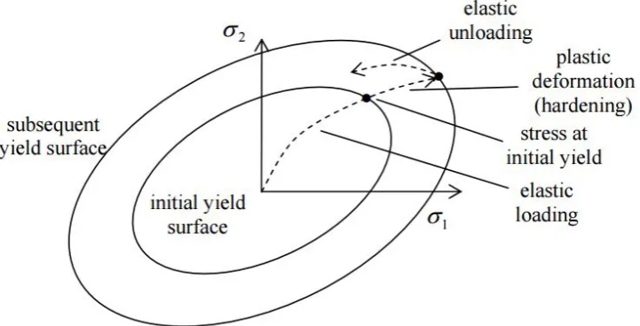
Isotropic hardening
The first type of plasticity hardening is known as isotropic hardening. For this particular hardening the yield surface grows bigger in size meanwhile the centre remains at fixed position in the stress space as shown in Figure 2.11. For isotropic hardening, if plastically deform a solid, then unload it, then try to reload it again, its yield stress (or elastic limit) would have increased compared to what it was in the first cycle (Rees, 2012). Again, when the solid is unloaded and reloaded, yield stress (or elastic limit) further increases. as long as it is reloaded past its previously reached maximum stress. This advances until a stage (or a cycle) is reached that the solid deforms elastically throughout this isotropic hardening.
21
Figure 2.11: Isotropic hardening yield surface (Rees, 2012)
Kinematic hardening
Kinematic hardening is the second type of plasticity hardening. Unlike isotropic hardening, the centre of the yield surface translates in stress space, while the yield surface size remains fixed in this hardening as illustrated in Figure 2.12. In order to model the Bauschinger effect and similar responses, where a hardening in tension will lead to a softening in a subsequent compression, one can use the kinematic hardening rule (Rees, 2012; Chaboche, 1991). The Bauschinger effect refers to a property of materials where the material’s stress/strain characteristics change as a result of the microscopic stress distribution of the material.
[image:41.595.153.514.98.282.2]22
Figure 2.12: Kinematic hardening yield surface (Rees, 2012)
Combined isotropic-kinematic hardening
The third type of yield surface evolution is known as combined isotropic-kinematic hardening where both isotropic and kinematic hardening properties are present (Axelsson & Samuelsson, 1979; Bathe & Montáns, 2004). In the combined isotropic-kinematic hardening, yield surface orientation might change as well. Although isotropic hardening is the most common form of yield surface evolution utilized in FE models for plastic deformation simulation, it is not necessarily the most accurate (Eterovic & Bathe, 1990). The combined isotropic-kinematic hardening model can considered as the most accurate from the three types of hardening models.
This hardening model consists of two components which are kinematic hardening component and isotropic hardening component. The non-linear kinematic hardening component explains the yield surface translation in stress space via the back stress. The isotropic hardening component explains the transformations of the equivalent stress defining the size of the yield surface as a function of plastic deformation. Combined isotropic-kinematic hardening will demonstrate the real material characteristics as it displaying both isotropic and kinematic hardening behaviour (Kang, 2010).
Wear
[image:42.595.161.506.80.242.2]23
addition, wear mechanism can be classified as mechanical, chemical and thermal wear while wear modes classified as abrasive, adhesive, flow and fatigue wear (Stachowiak, 2006). The process of deformation and fracturing is considered as mechanical wear, where the deformation process takes place in ductile material and fracture occur in brittle materials.
Wear occurs almost in every components and devices including teeth and bone joints, piston rings, roads, tires, dirt seals, brakes, liquid seals, belts, floor, fabrics, shoes, electrical contacts, CD reader heads, cannon barrels, dies, rolling mills, forgings, conveyors, ore crushers, home appliances, door hinges, zippers, saws, drills, pump impellers, razor blades, pipe bends, valve seats, erasers, plastic moulding screw and others as well (Ludema, 1996). Basically, yielding and plastic deformation will lead to wear of material as shown in Figure 2.13 (Tobi et al., 2009). An attention should be given in minimising plastic deformation of material in order to protect the material from wear, thus can prolong the lifetime of engineering components.
Figure 2.13: Process of delamination wear mechanism (Tobi et al., 2009)
Generally, plastic deformation and wear should be eliminated or reduced to ensure efficiency of materials or machinery in order to enhance its performance. There are some plastic deformation and wear reduction steps such as:
• Retain low contact pressure
• Retain low sliding speed
[image:43.595.156.500.363.520.2]24
• Usage of hard materials
• Ensure low friction coefficient
• Apply a lubricant/coating
2.4 Coating and Substrate
Coating can be referred as a covering that is applied on the surface of an object or substrate as shown in Figure 2.14. Coating can be used for decorative purposes, functional purposes or sometimes both. Coating which covering the substrate completely is known as all-over coating while some coatings only cover certain part of the substrate. The major purpose of coating is to alter the component’s surface properties to ensure substrate material bulk characteristics can be exploited when unsupportable situation occurs (Strawbridge & Evans, 1995). Obviously, coatings are widely used in engineering applications especially, manufacturing, automotive and aeroengine industries in order to reduce friction, increase resistance of plastic deformation and wear on contact surfaces (Mohd Tobi et al., 2013). There are few type of coatings that widely used such as surface welding coatings, thermal spraying coatings, electro deposition coatings, plastic coatings, physical and chemical vapour deposition coatings.
A substrate is known as a primary or underlying substance or layer as shown in Figure 2.14. Normally, substrate is surface of an object where other materials for instance, coating, ink, paint or treatment are enforced. Moreover, a substrate also can be defined as medium or solid substance where another substance is applied where the adherence of second substance occurs. Generally, the purpose of the coating is to protect the surface of the substrate to maximise life time of the substrate.
[image:44.595.232.415.602.729.2]References
Aslantas, K. & Tasgetiren, S. (2002). Debonding between coating and substrate due to rolling–sliding contact. Materials & design, 23(6), pp. 571–576.
Axelsson, K. & Samuelsson, A. (1979). Finite element analysis of elastic–plastic materials displaying mixed hardening.International Journal for Numerical Methods in Engineering, 14(2), pp. 211–225.
Bathe, K.J. & Montáns, F.J. (2004). On modeling mixed hardening in computational plasticity. Computers & structures, 82(6), pp. 535–539.
Benedetti, M. & Fontanari, V. (2004). The effect of bi-modal and lamellar microstructures of ti-6al-4v on the behaviour of fatigue cracks emanating from edge-notches. Fatigue & fracture of engineering materials & structures, 27(11), pp. 1073–1089.
Bhushan, B. & Gupta, B.K. (1991). Handbook of tribology: materials, coatings, and surface treatments.
Brekelmans, W. & De Vree, J. (1995). Reduction of mesh sensitivity in continuum damage mechanics. Acta Mechanica, 110(1-4), pp. 49–56.
Bressan, J., Tramontin, A. & Rosa, C. (2005). Modeling of nanoindentation of bulk and thin film by finite element method. Wear, 258(1), pp. 115–122.
Bull, S. (1991). Failure modes in scratch adhesion testing. Surface and Coatings Technology, 50(1), pp. 25–32.
Bull, S. & G-Berasetegui, E. (2006). An overview of the potential of quantitative coating adhesion measurement by scratch testing. Tribology and Interface Engineering Series, 51, pp. 136–165.
180
Cai, W., Cuerden, B., Parks, R.E. & Burge, J.H. (2011). Strength of glass from hertzian line contact. In: SPIE Optical Engineering+ Applications, International Society for Optics and Photonics, pp. 81250E–81250E.
Cai, X. (1993). Effect of friction in indentation hardness testing: a finite element study. Journal of materials science letters, 12(5), pp. 301–302.
Calamaz, M., Coupard, D. & Girot, F. (2008). A new material model for 2d numerical simulation of serrated chip formation when machining titanium alloy ti–6al–4v.International Journal of Machine Tools and Manufacture, 48(3), pp. 275–288.
Chaboche, J.L. (1991). On some modifications of kinematic hardening to improve the description of ratchetting effects. International journal of plasticity, 7(7), pp. 661–678.
Chakrabarty, J. (2006). Theory of plasticity. Butterworth-Heinemann.
Cheng, Y.T. & Cheng, C.M. (1998). Further analysis of indentation loading curves: Effects of tip rounding on mechanical property measurements. Journal of Materials research, 13(04), pp. 1059–1064.
Ciavarella, M. & Demelio, G. (2001). A review of analytical aspects of fretting fatigue, with extension to damage parameters, and application to dovetail joints. International Journal of Solids and Structures, 38(10), pp. 1791– 1811.
Creations, A. (2009). Matweb-material property data. Retrieved September, 16, p. 2009.
Demidova, N., Wu, X. & Liu, R. (2012). A fracture toughness model for brittle coating on ductile substrate under indentation loading.Engineering Fracture Mechanics, 82, pp. 17–28.
Dieter, G.E. & Bacon, D.J. (1986). Mechanical metallurgy, volume 3. McGraw-Hill New York.
Djabella, H. & Arnell, R. (1992). Finite element analysis of the contract stresses in an elastic coating on an elastic substrate. Thin Solid Films, 213(2), pp. 205–219.
181
Doerner, M., Gardner, D. & Nix, W. (1986). Plastic properties of thin films on substrates as measured by submicron indentation hardness and substrate curvature techniques. Journal of Materials Research, 1(06), pp. 845–851.
Dundurs, J. (1969). Discussion:edge-bonded dissimilar orthogonal elastic wedges under normal and shear loading(bogy, db, 1968, asme j. appl. mech., 35, pp. 460–466). Journal of applied mechanics, 36(3), pp. 650–652.
Eterovic, A.L. & Bathe, K.J. (1990). A hyperelastic-based large strain elasto-plastic constitutive formulation with combined isotropic-kinematic hardening using the logarithmic stress and strain measures.International Journal for Numerical Methods in Engineering, 30(6), pp. 1099–1114.
Ford, T. (1997). Mainshafts for the trent. Aircraft Engineering and Aerospace Technology, 69(6), pp. 555–560.
Fouvry, S., Kapsa, P. & Vincent, L. (2001). An elastic–plastic shakedown analysis of fretting wear. Wear, 247(1), pp. 41–54.
Gasca, M. & Sauer, T. (2000). Polynomial interpolation in several variables. Advances in Computational Mathematics, 12(4), pp. 377–410.
Grzesik, W. (2003). Advanced protective coatings for manufacturing and engineering. Hanser Gardner Publications.
Gupta, P.K. & Walowit, J. (1974). Contact stresses between an elastic cylinder and a layered elastic solid. Journal of Tribology, 96(2), pp. 250–257.
Gurtin, M.E. (1973). The linear theory of elasticity. In: Linear Theories of Elasticity and Thermoelasticity, Springer, pp. 1–295.
Hazelrigg, G.A. (2003). Validation of engineering design alternative selection methods. Engineering Optimization, 35(2), pp. 103–120.
Hibbeler, R. (2011). Mechanics of materials.
Holmberg, K., Ronkainen, H. & Matthews, A. (2000). Tribology of thin coatings. Ceramics International, 26(7), pp. 787–795.
Holmberg, K., Laukkanen, A., Ronkainen, H. & Wallin, K. (2006). Tribological analysis of fracture conditions in thin surface coatings by 3d fem modelling and stress simulations. Tribology international, 38(11), pp. 1035–1049.
182
Holmberg, K., Ronkainen, H., Laukkanen, A. & Wallin, K. (2007). Friction and wear of coated surfacesscales, modelling and simulation of tribomechanisms. Surface and Coatings Technology, 202(4), pp. 1034– 1049.
Huajian, G., Cheng-Hsin, C. & Jin, L. (1992). Elastic contact versus indentation modeling of multi-layered materials. International Journal of Solids and Structures, 29(20), pp. 2471–2492.
Hutchings, I.M. (1992). Tribology: friction and wear of engineering materials.
Hyde, T.R. (2002). Development of a representative specimen for fretting fatigue of spline joint couplings. Ph.D. thesis, Nottingham University.
Johnson, K.L. & Johnson, K.L. (1987).Contact mechanics. Cambridge university press.
Joslin, D. & Oliver, W. (1990). A new method for analyzing data from continuous depth-sensing microindentation tests. Journal of Materials Research, 5(01), pp. 123–126.
Kang, S. (2010). Friction and elasto-plastic deformation in asperity collision.
Kataria, S., Goyal, S., Dash, S., Sandhya, R., Mathew, M. & Tyagi, A. (2012). Evaluation of nano-mechanical properties of hard coatings on a soft substrate. Thin Solid Films, 522, pp. 297–303.
Kienzler, R. & Herrmann, G. (2012). Mechanics in material space: with applications to defect and fracture mechanics. Springer Science & Business Media.
King, R. (1987). Elastic analysis of some punch problems for a layered medium. International Journal of Solids and Structures, 23(12), pp. 1657–1664.
Komvopoulos, K. (1989). Elastic-plastic finite element analysis of indented layered media. Journal of Tribology, 111(3), pp. 430–439.
Korsunsky, A., McGurk, M., Bull, S. & Page, T. (1998). On the hardness of coated systems. Surface and Coatings Technology, 99(1), pp. 171–183.
183
Koutsomichalis, A., Vaxevanidis, N., Petropoulos, G., Xatzaki, E., Mourlas, A. & Antoniou, S. (2009). Tribological coatings for aerospace applications and the case of wc-co plasma spray coatings. Tribology in industry, 31(1-2), pp. 37–42.
Lal, G. & Reddy, N.V. (2009). Introduction to engineering plasticity. Alpha Science International Limited.
Leen, S., Hyde, T., Ratsimba, C.H., Williams, E. & McColl, I. (2002). An investigation of the fatigue and fretting performance of a representative aero-engine spline coupling. The Journal of Strain Analysis for Engineering Design, 37(6), pp. 565–583.
Leen, S., Richardson, I., McColl, I., Williams, E. & Hyde, T. (2001). Macroscopic fretting variables in a splined coupling under combined torque and axial load. The Journal of Strain Analysis for Engineering Design, 36(5), pp. 481–497.
Lovell, M. (1998). Analysis of contact between transversely isotropic coated surfaces: development of stress and displacement relationships using fem. Wear, 214(2), pp. 165–174.
Ludema, K.C. (1996). Friction, wear, lubrication: a textbook in tribology. CRC press.
Madge, J., Leen, S., McColl, I. & Shipway, P. (2007). Contact-evolution based prediction of fretting fatigue life: effect of slip amplitude. Wear, 262(9), pp. 1159–1170.
Manual, A.U. (2013). Version 6.13-2. Dassault Systémes Simulia Corp., Providence, Rhode Island, USA.
Martinez, E., Romero, J., Lousa, A. & Esteve, J. (2003). Nanoindentation stress–strain curves as a method for thin-film complete mechanical characterization: application to nanometric crn/cr multilayer coatings. Applied Physics A, 77(3-4), pp. 419–427.
McColl, I., Ding, J. & Leen, S. (2004). Finite element simulation and experimental validation of fretting wear. Wear, 256(11), pp. 1114–1127.
184
Mesarovic, S.D. & Fleck, N.A. (1999). Spherical indentation of elastic–plastic solids. In: Proceedings of the Royal Society of London A: Mathematical, Physical and Engineering Sciences, volume 455, The Royal Society, pp. 2707–2728.
Michler, J. & Blank, E. (2001). Analysis of coating fracture and substrate plasticity induced by spherical indentors: diamond and diamond-like carbon layers on steel substrates. Thin solid films, 381(1), pp. 119–134.
Mohd Tobi, A., Shipway, P. & Leen, S. (2011). Gross slip fretting wear performance of a layered thin w-dlc coating: Damage mechanisms and life modelling. Wear, 271(9), pp. 1572–1584.
Mohd Tobi, A., Shipway, P. & Leen, S. (2013). Finite element modelling of brittle fracture of thick coatings under normal and tangential loading. Tribology International, 58, pp. 29–39.
Munjiza, A. & John, N. (2002). Mesh size sensitivity of the combined fem/dem fracture and fragmentation algorithms. Engineering Fracture Mechanics, 69(2), pp. 281–295.
Needleman, A. (1988). Material rate dependence and mesh sensitivity in localization problems. Computer methods in applied mechanics and engineering, 67(1), pp. 69–85.
Oliveira, S.A. & Bower, A.F. (1996). An analysis of fracture and delamination in thin coatings subjected to contact loading. Wear, 198(1), pp. 15–32.
Olver, P.J. (2006). On multivariate interpolation.Studies in Applied Mathematics, 116(2), pp. 201–240.
Page, T.F. & Hainsworth, S.V. (1993). Using nanoindentation techniques for the characterization of coated systems: a critique. Surface and Coatings Technology, 61(1), pp. 201–208.
Panich, N. & Sun, Y. (2004). Effect of penetration depth on indentation response of soft coatings on hard substrates: a finite element analysis. Surface and Coatings Technology, 182(2), pp. 342–350.
185
Prevost, J.H. (1985). A simple plasticity theory for frictional cohesionless soils. International Journal of Soil Dynamics and Earthquake Engineering, 4(1), pp. 9–17.
Rajasekaran, R. & Nowell, D. (2006). Fretting fatigue in dovetail blade roots: experiment and analysis. Tribology international, 39(10), pp. 1277–1285.
Rees, D. (2012). Basic engineering plasticity: an introduction with engineering and manufacturing applications. Butterworth-heinemann.
Roesler, J., Harders, H. & Baeker, M. (2007).Mechanical behaviour of engineering materials: metals, ceramics, polymers, and composites. Springer.
Saniee, K. (2008). A simple expression for multivariate lagrange interpolation.
Sauer, T. & Xu, Y. (1995). On multivariate lagrange interpolation.Mathematics of Computation, 64(211), pp. 1147–1170.
Sciamanna, V., Nait-Ali, B. & Gonon, M. (2015). Mechanical properties and thermal conductivity of porous alumina ceramics obtained from particle stabilized foams. Ceramics International, 41(2), pp. 2599–2606.
Siswanto, W.A., Nagentrau, M., Tobi, M., Latif, A. & Tamin, M. (2015). Contact pressure prediction comparison using implicit and explicit finite element methods and the validation with hertzian theory. International Journal of Mechanical & Mechatronics Engineering, 15(6), pp. 1–8.
Stachowiak, G.W. (2006).Wear: materials, mechanisms and practice. John Wiley & Sons.
Steffensen, J.F. (2006). Interpolation. Courier Corporation.
Strawbridge, A. & Evans, H.E. (1995). Mechanical failure of thin brittle coatings. Engineering Failure Analysis, 2(2), pp. 85–103.
Sun, Y., Bloyce, A. & Bell, T. (1995). Finite element analysis of plastic deformation of various tin coating/substrate systems under normal contact with a rigid sphere. Thin Solid Films, 271(1), pp. 122–131.
Systèmes, D. (2013). Abaqus 6.13 theory manual. Dassault Systèmes Simulia Corp., Providence, Rhode Island.