A WALLABLE MACRODEVICE
Keith Waters
Robert A. Iannucci
99-6
_______________________________________________________________________
Cambridge Research Laboratory
The Cambridge Research Laboratory was founded in 1987 to advance the state of the art in both core computing and human-computer interaction, and to use the knowledge so gained to support the Company's corporate objectives. We believe this is best accomplished through interconnected pursuits in technology creation, advanced systems engineering, and business development. We are actively investigating scalable computing; mobile computing; vision-based human and scene sensing; speech interaction; computer-animated synthetic persona; intelligent information appliances; and the capture, coding, storage, indexing, retrieval, decoding, and rendering of multimedia data. We recognize and embrace a technology creation model which is characterized by three major phases:
Freedom: The lifeblood of the Laboratory comes from the observations and imaginations of our research staff. It is here that challenging research problems are uncovered (through discussions with customers, through interactions with others in the Corporation, through other professional interactions, through reading, and the like) or that new ideas are born. For any such problem or idea, this phase culminates in the nucleation of a project team around a well-articulated central research question and the outlining of a research plan.
Focus: Once a team is formed, we aggressively pursue the creation of new technology based on the plan. This may involve direct collaboration with other technical professionals inside and outside the Corporation. This phase culminates in the demonstrable creation of new technology which may take any of a number of forms—a journal article, a technical talk, a working prototype, a patent application, or some combination of these. The research team is typically augmented with other resident professionals—engineering and business development—who work as integral members of the core team to prepare preliminary plans for how best to leverage this new knowledge, either through internal transfer of technology or through other means.
Follow-through: We actively pursue taking the best technologies to the marketplace. For those opportunities which are not immediately transferred internally and where the team has identified a significant opportunity, the business development and engineering staff will lead early-stage commercial development, often in conjunction with members of the research staff. While the value to the Corporation of taking these new ideas to the market is clear, it also has a significant positive impact on our future research work by providing the means to understand intimately the problems and opportunities in the market and to more fully exercise our ideas and concepts in real-world settings.
Throughout this process, communicating our understanding is a critical part of what we do, and participating in the larger technical community—through the publication of refereed journal articles and the presentation of our ideas at conferences—is essential. Our technical report series supports and facilitates broad and early dissemination of our work. We welcome your feedback on its effectiveness.
Robert A. Iannucci, Ph.D.
Abstract
A Wallable Macro Device
Keith Waters
Robert A. Iannucci
17th September 1999
Compaq Computer Corporation 1999
This work may not be copied or reproduced in whole or in part for any commercial purpose. Permission to copy in whole or in part without payment of fee is granted for nonprofit educational and research purposes provided that all such whole or partial copies include the following: a notice that such copying is by permission of the Cambridge Research Laboratory of Compaq Computer Corporation in Cambridge, Massachusetts; an acknowledgment of the authors and individual contributors to the work; and all applicable portions of the copyright notice. Copying, reproducing, or republishing for any other purpose shall require a license with payment of fee to the Cambridge Research Laboratory. All rights reserved.
CRL Technical reports are available on the CRL's web page at http://www.crl.research.digital.com.
Compaq Computer Corporation Cambridge Research Laboratory One Kendall Square, Building 700, Suite 721
1.0 Introduction
Tomorrow’s computing appliances will appear in a wide variety of form factors. As a result these appliances will no longer be constrained by the traditional WIMP desktop that has for the past twenty years dictated the development of user interfaces. Instead the form factor itself will regulate the user interface; small electronic devices, such as palm size computers, will require unique interfaces that differ from those found in large freestanding appliances, such as a kiosk. Typically, kiosks require the user to be standing facing the display where interactions are simple and brief. Asking users to type at a keyboard, or even use a mouse, while standing is at best awkward and cumbersome. Consequently, we need to develop new approaches to user interface design that are quite unlike what we see today.
At CRL we believe that tomorrow’s interfaces will focus on human-centered interactions; in particular interfaces that adapt to human modes of interaction rather than humans adapting to machines [1]. Constructing such interfaces is non-trivial, as systems will have the complex task of detecting, interpreting and responding to users. However, we believe that appliances that become capable of interpreting human modes of communication --- such as human detection, body language, speech and facial expression --- will have significant advantages for everyday users. This document describes one such initiative. As the name suggests a Wallable macro-device is a large-scale appliance that can be placed on, or in the wall itself. The objective is to create a Message Panel, where simple audio/visual messages can be presented and accessed by visitors, or lab members, when arriving at the laboratory. In such a location short-term visitors and lab members can activate and interact with the appliance by simply being present in front of images projected on a wall. Obviously, this scenario can also be applied to alternative situations such as living rooms or shopping malls, but in this case it is assumed to be a panel situated in the reception area of our research laboratory.
1.1 Previous Work
Although vision-based human sensing has received a great deal of attention in the past five years, there remain only a small handful of operational systems. In part this is due to the complexity of constructing and maintaining prototypes, but due largely to the fact that it is difficult to construct complete solutions that integrate with traditional operating systems and applications. The reader is referred to Human-Machine Interaction, for a more complete review of systems in this area [2]. The Cambridge Research Laboratory is activity investigating Human Centered Interaction technologies for a number of years. The Smart Kiosk is a culmination of research originating with investigations into using computer vision algorithms to sense, track and respond to users [1]. These prototypes were large situated freestanding boxes with touch screen monitors and a talking face for user feedback [2].
2.0 Design Goals
The design of the Wallable macro device had a number of constraints and goals. These include:
• Computation. The application has to operate on a single processor Compaq platform. In
this instance a Presario 5660 450Mhz PII running W98.
• Low cost camera. The camera requires no special purpose frame grabbing board or
custom frame grabber. A single inexpensive USB Kodak DV323 camera was used for this purpose (for which only W98 camera drivers were available).
• Human presence detection. The ability to detect the users location when in proximity to
the device.
• Rapid Prototyping. An ability to reconfigure the basic components was a necessity. • Real-time audiovisual feedback. Providing feedback to the user as to the state of the
device. A feature of all interactive scenarios is to clearly provide information to the user the state of the device in a timely and intuitive fashion. To achieve this we use a real-time talking face capable of focusing attention and speaking to the user.
3.0 Implementation
As a rule system architecture issues are secondary to the research aims and are often superficially described. However, in our case, the choice of tools and implementation details played a pivotal role in achieving the goals described above. At the outset the implementation had to operate on the Windows platform. While Windows does not allow the development of a fine-grained real-time OS, the Wallable macro device project was not about to create its own. In addition, the use of a low-cost USB camera dictated that the use of W98 because the availability of USB drivers, at the time of development, was restricted to W98.
The Wallable macro device-programming model is based on the Component Object Model (COM) and OLE Automation. Devices, or sensing components, are modeled as ActiveX components that expose properties and methods for control (see Appendix A and B). When a method associated with a component is modified the object converts it to a unique autonomous operation for that component and returns the state back to the caller. As a result, the components can exist independently from one another.
COM provides the necessary code modularity, and provided the development is continued within additional IDE (Integrated Development Environments) such as VBScript, MS J++ and MS VC++, code reconfiguration is straightforward. The visual representation of components and the automatic generation of code within such IDE promote rapid development and therefore satisfy one of the design goals for this project.
4.0 Architecture Overview
large wall. In this configuration the active area becomes what can be observed from the cameras viewpoint.
Figure 1. The Wallable macro device layout.
A rear screen projector, connected to the PC, provides the display for the user. Lighting is extremely important for the vision algorithms to function effectively. In this case diffuse top light and a carpeted floor reduces reflections and shadowing effects that can cause the vision algorithms to fail. As the user approaches the display the user enters the view of the camera, or active region triggering various events to occur.
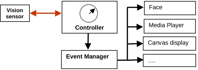
4.1 Flow Control
At the heart of the system are the Controller and Event Manager (see Figure 2). The Controller is responsible for processing the sensed data. In this case periodic requests (every 350 milliseconds) are fired to the vision sensor with a reply as the to state of some part of the scene.
Figure 2. Flow Control architecture.
Controller Vision
sensor
Event Manager
Face
Media Player
Canvas display
…. 15 ft
Projector
PC
USB camera x
y y
[image:7.612.136.466.523.640.2]Based on the returned state, the Event Manager triggers events. Each event is self-contained and runs to completion unless interrupted with an additional event trigger. Essentially, this type of flow control is the same as a standard event driven Windows application where the mouse and keyboard are replaced by the vision sensor events.
5.0 Component Technologies
In the example of the Message Panel there are three basic component technologies, the container, the vision sensor and the face. The container is an additional COM component into which the others are placed and controlled. Simple messages are relayed to the various components via the Controller as described above.
5.1 The Vision-based Sensor
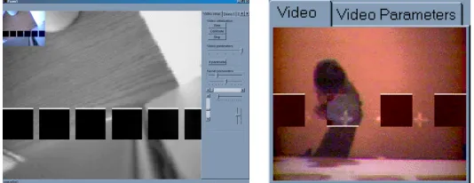
[image:8.612.165.432.377.480.2]The vision sensor is the mechanism for detecting the presence, or absence of the user. The algorithms for such a sensor can become complex. For example, it could have been designed to detect humans based on color histograms [3], whole bodies by templates [5], or faces using neural network detectors [6]. However, the computational expense restricted the human detection to a computationally tractable operation. Effectively, the vision sensors task is to identify activity within a specific region, known as a kernel, and report its state back to the caller. Higher-level application functionality can be simply achieved by chaining multiple kernels together. Figure 4 illustrates the active area captured by the camera and the dark areas are the individual kernels.
Figure 3. Two views of the video sensor. On the left there are six kernels evenly spaced, while on the right
only four. On the right is a view of an individual being detected. The white horizontal bar indicating the activity within the kernel itself.
An advantage of the kernels is that only a predefined region of the captured scene is efficiently processed. Furthermore, the number, shape, size and location of the kernels can be configured for a particular application. In our case, it was desirable to map kernels to four events in the container.
The peak performance characteristics of the USB camera is ~12Mb/sec. At this rate it is only possible to access and process uncompressed images in a YUV I420 format at 176 x 144 x 12bits QCIF at rates high enough to maintain interactive performance rates1. Each kernel defaults to 40x40 pixels however; they can be reshaped and positioned.
1
The operation within each kernel is a difference operator, where
b
is a static background,c
is the current frame andd
is the difference frame. The algorithm uses the Y luminance component only from the I420 format. For each pixel for following operation is performedd
i,j=
b
i,j−
c
i,j ,where i,j, is a unique pixel array index. The resulting pixel difference summations within a kernel are then compared to a predefined threshold t. If
d
is greater than the threshold, it is assumed that there is activity within the region and the next operation, to identify the first scanline on which there is activity, greater than a predefined threshold is preformed. The first scanline is then returned back to the caller identifying the location within the kernel. The dark areas in Figure 3 are the display of the difference images.The performance of the kernel detector is critically dependent on the original calibration frame
b
, which is created once at the beginning of the session. Drift, especially when lighting conditions change, causes large variations ind
and can therefore cause the sensor to trigger events. To prevent this happening a re-calibration phase can be simply added with timing component added that looks at the duration of stability of the image. If it has been stable for a predefined period, then a new background calibration image is stored.5.2 The Face
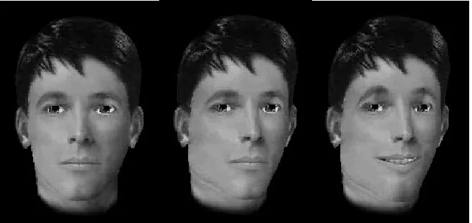
[image:9.612.140.475.422.580.2]The face technology provides a direct and immediate feedback to the user. The face technology is the client of FaceWorks, a Multimedia authoring tool for face characters [6]. The face is capable of facing the user, facial expression and speech. Simple behaviors, such as smiling, are scripted and called by the user as seen in Figure 4.
Figure 4. Three example poses of the synthetic face created by FaceWorks, (1) Static, (2) rotated ¾ view
and (3) smiling and talking. The face is the principal feedback mechanism in the Wallable macro device.
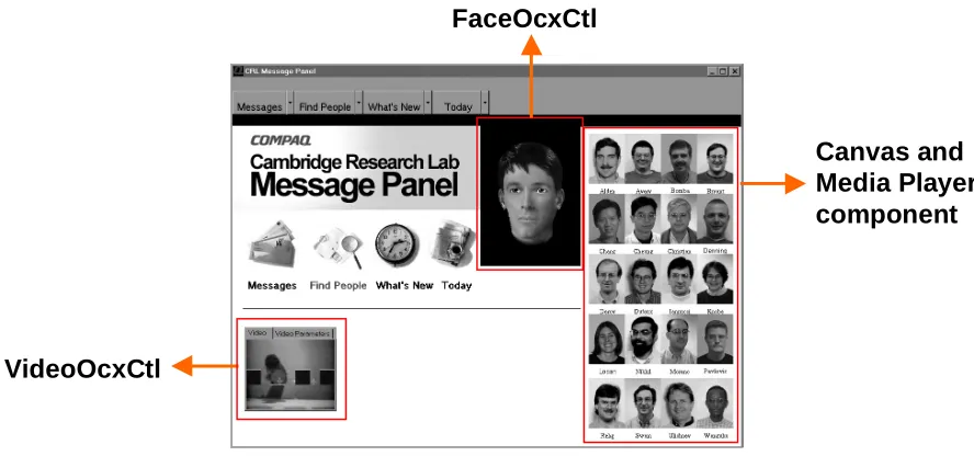
5.3 The Container
The principle task of the container is to mediate transactions, pass state control to the other components and to provide the visual display of the interface. Figure 5 illustrates the final display of the container and the visible components. There are four basic functions of the message panel: (1) Messages, (2) Find people, (3) What’s New and (4) Today. Each section has distinct functionality, for example the Messages section plays video clips via the Microsoft Media Player,
Find People displays a map of the lab, while the face describes where the user is in relation to the
[image:10.612.84.528.213.421.2]Message Panel.
Figure 5. The Message Panel with three active components, the Face and the Video Ocx’s and a canvas
display. The particular activity of the Message Panel is as follows: the video display shows an individual activating the “Find People” functionality, above the label within the container highlights, the canvas
displays bitmaps of lab members while the face describes the location of the user in relation to the researchers.
The J++ code sample below describes the basis of the control. The structure is the form of an event that triggers every 350 milliseconds. A status check is made to the VideoOcxCtl via the GetKernelStats and then each kernel status is processes depending on which of the four basic function modules it belongs too. The J++ code sample illustrates the control structure for no activity: -1, the Messages active: 0, Find People active: 1 and an arbitrary activity n.
private void globaltimer_timer ( Object source, Event e ) {
if ( VideoRunning ) {
GetKernelStats ( ) ; // Get status from the video OCX
labels.setVisible ( false ) ; // Turn all the labels off
// Check the kernels for activity, ONLY one can be active at a time. switch ( SelectActiveKernel ( ) ) {
case -1: // Nothing there, so reset the kernels
VideoOcxCtl
ResetToday ( ) ; ResetMessage ( ) ; ResetFindPeople ( ) ; ResetWhatsNew ( ) ; TurnOffOnPeopleImages ( false ) ; TurnOffOnMapandArrow ( false ) ;
eyelids = 1.0 ; // Make the head look as if it is asleep posx = 7 ;
break ;
case 0: // The Message box has been activated
pictureBox30.setVisible ( true ) ; // Message label ON.
Messages ( ) ; // Interpret which message
posx = 3 ; // Turn the head to the location of the message box posy = -15 ;
posz = 0 ; eyelids = 0.0 ;
break ;
case 1: // The FindPeople label has been activated
label6.setVisible ( true );
Findpeople ( );
posx = 3 ; // Turn the head to the find people label posy = -10 ;
posz = 0 ; eyelids = 0.0 ; break ;
case n: // Active State
label[n].setVisible ( true ) ; // Set the display for the labels
Action[n] ; // Take the necessary action, and display result
SetHeadPoseVectors ( n ) ; // Set the head and expressions break ;
}
// Finally, set the head position and eye behavior FaceOcxCtl1.SetHeadPosition ( posx, posy, posz ) ; FaceOcxCtl1.SetEyelids ( eyelids ) ;
FaceOcxCtl1.SetGaze ( gazex, gazey, gazez ) ;
} }
6.0 Conclusion
The Wallable macro device met all the original design goals and has subsequently been demonstrated to large audiences with conference size projection facilities as well as experimental setups with the research lab. In both instances, the system behaved consistently. Latencies, one of the principle concerns at the outset, were low enough to allow effective interactive rates. The time from detection to when the face spoke would be less than a second, which is well within an acceptable range of human computer interaction.
The basic framework of the Wallable macro device provides easy access to the basic components via J++ or any other IDE scripting language. As a result, creating and testing new architectures was easily achieved thereby meeting one of the principle goals of the project. Accommodating new sensing components, such as command control speech, within the framework would be straightforward and provide a richer, multi-modal input interaction.
Appendix A: The VideoOcxCtl
The VideoOcxCtl has a number of methods that break down into some two basic sub-groups, those that control the video, such as positioning and brightness, and those methods that control the kernel states, such as size, separation and position. In the case of the Wallable macro device one additional method was created that predefined the number four kernels of a specific shape, location and size. This was not a generalized method call and omitted from the list below.
• VideoOcxCtrl::SetNumKernels
short SetNumKernels(
[in] short inum ) ;
This method instructs the video component to set the number of kernels to process. The kernels are evenly dispersed depending on the kernel gap size and kernel scanline position. All the kernels are horizontally aligned.
inum A non-negative number of kernels to process in the range of 1-30.
• VideoOcxCtrl::KernelGap
short KernelGap(
[in] short iGap ) ;
Modifies the gap between each successive kernel. This information is used to re-computes the size of the kernels to fit the width of the digitized video. Once this has been called it will automatically call VideoOcxCtl::Calibrate.
iGap A short integer in pixels in the rage of 0-20 pixels.
• VideoOcxCtrl::KernelState
short KernelState( ) ;
Notifies the caller, via the return value, all the kernel states. This method requires
VideoOcxCtl::ResetKernelStatus to the called. • VideoOcxCtrl::AudioPlayFileName
short AudioPlayFileName(
[in] BSTR nameOfFile ) ;
This method instructs the video component to play a specified audio file. This can be used in conjunction with button activation.
nameOfFile The name of the wav file to play
• VideoOcxCtrl::Stop
short Stop ( ) ;
Notifies the video component to stop processing the streamed data. • VideoOcxCtrl::DisplayVideo
short DisplayVideo ( ) ;
Notifies the video component to display the live video stream to the currently selected canvas.
• VideoOcxCtrl::IncrementKernels
Notifies the video component to increment the kernel count by one. The maximum number of kernels is fifty.
• VideoOcxCtrl::DecrementKernels
short DecrementKernels ( ) ;
Notifies the video component to decrement the kernel count by one. The minimum number of kernels is one.
• VideoOcxCtrl::Calibrate
short Calibrate( ) ;
Notifies the video Ocx component to calibrate using a snapshot of the background scene. This image will over write the current stored background.
• VideoOcxCtl::Initialize
short Initialize ( ) ;
Notifies the video component to initialize the component and start streaming I420 YUV CIF format data into memory.
• VideoOcxCtrl::SetVideoProperties
short SetVideoProperties ( ) ;
Sets the video properties for the video capture device through a dialog box. This method call and displays a dialog box in which the user can control the video source. The Video Source dialog box might contain controls that select input sources; alter the hue, contrast, and brightness of the image; and modify the video quality before digitizing the images into the frame buffer.
Returns S_OK on success, otherwise returns an error code.
• VideoOcxCtrl::SetKernelSize
short SetKernelSize ( [in] short x [in] short y ) ;
Notifies the video component that the kernels are to be reshaped. This operation automatically calls VideoOcxCtl::Calibrate.
x the size of the new kernel in pixels y the size of the new kernel in pixels
Appendix B: The FaceOcxCtl
The FaceOcxCtl methods are a subset of all the methods that are available in FaceWorks. In this instance there is sufficient functionality in those described below to implement a rich feedback interface. To create the macro level expressive capabilities, such as talking and nodding the head, a *.fa file should be created from FaceWorks. The *.fa files encapsulate the temporal data for the facial expressions, head motions, the lip postures into a single file that can be loaded via the
FaceOcxCtl::OpenFaFile, and subsequently played back via the FaceOcxCtl::Play method call.
• FaceOcxCtl::Play
HRESULT Play ( ) ;
Notifies the Face component to play the currently loaded *.fa (facial animation) file. A *.fa file comprises of a wav file and face actions.
• FaceOcxCtl::Initialize
HRESULT Initialize ( ) ;
Notify the face component to create an instance of the face. The face geometry is created from file and the display initialized.
HRESULT Stop ( ) ;
Notifies the face component to halts the playing of the current *.fa file. • FaceOcxCtl::OpenFaFile
HRESULT OpenFaFile ( BSTR FileName ) ;
Notifies the face component to open a *.fa file (facial animation file) created from FaceWorks studio.
FileName the *.fa file name of the file to open.
• FaceOcxCtl::OpenFdFile
HRESULT OpenFdFile ( BSTR FileName ) ;
Notifies the face component to open a *.fd file (face data file) created from FaceWorks studio. The *.fd file consists of geometry, images and other data to create a face.
FileName the *.fd file name of the file to open.
• FaceOcxCtl::SetHeadPosition
HRESULT SetHeadPosition ( [in] float x,
[in] float y, [in] float z ) ;
Notifies the face component to set the orientation of the head.
x in the range of 0.0-10.0. y in the range of 0.0-10.0. z in the range of 0.0-10.0.
• FaceOcxCtl::SetEyelids
HRESULT SetEyelids ( [in] float val ) ;
Notifies the face component to set the eyelid opening in the range of 0-10, where 0 is shut.
val a float value defining the opening of the eyelids, in the range of 0.0-10.0.
• FaceOcxCtl::SetMouthPosition
HRESULT SetMouthPosition ( [in] short id ) ;
Notifies the face component to set the mouth position to via the id. The id references one of the 76 phones used for the mouth shape mappings in FaceWorks. The IPA phoneme list is used to map to visemes their visible counterpart.
• FaceOcxCtl::SpeakVisemeNow
HRESULT SpeakVisemeNow ( [in] float elapsed, [in] float duration, [in] short current, [in] short next ) ;
Notifies the face component to set the mouth posture to be in between two visemes current and next.
elapsed the duration since the start of the interval duration the total duration for the interval current the phoneme id
next the next phoneme id
• FaceOcxCtl::SetGaze
[in] float y, [in] float z ) ;
Notifies the face component to sets the orientation of the eyes to a specific location.
x the 3-space location to look at. y the 3-space location to look at. z the 3-space location to look at.
7.0 References
[1] K. Waters. J. Rehg, M. Loughlin, S. B. Kang and D. Terzopoulos, Visual Sensing of Humans for Active Public Interfaces, Cambridge Research Laboratory, Technical Report Series CRL 96/5, March 1995.
[2] R. Cipolla and A. Pentland, Computer Vision for Human-Machine Interaction, Cambridge University Press, 1998.
[3] A. Christian and B. Avery, Digital Smart Kiosk, ACM SIGGCHI, Los Angeles, CA, April 1998.
[4] M. Swain and D. Ballard. Color Indexing. International Journal of Computer Vision, Volume 7, Number 1, pages 11-32, 1991.