Electrical Safety Analyzer for Biomedical
Equipment
Rajavardhan Reddy G1, Vanitha R2, A Nandan Kumar3, P Venkatesh4, Rajashekar K5, Hanumantha Reddy6 1,2,3,4 Electrical and Electronics Department, RYMEC College of Engineering, VTU University
5,6Asst. Professor Electrical and Electronics Department, RYMEC College of Engineering, VTU University
Abstract: In order to achieve the required high level of electrical safety in electro-medical equipment. To develop standards and guidelines to control their design as well as their use in hospitals and other health care delivery settings. It is highly essential that periodic preventive maintenance and electrical safety checks on all electro-medical equipment in use be carried out and records of these be maintained. International standard for routine testing of medical equipments at hospitals and clinics is International Electro technical Commission (IEC) 62353. This paper deals with the design and development of an indigenous Medical Electrical Safety Analyzer, which will conduct safety tests as per this standard. The safety tests like Earth bond test, Leakage current and Insulation tests to be conducted as per the standard are also discussed.
Keywords: Current measurement, Leakage current, Electrical safety, Electrical resistance measurement, IEC standards, Insulation, Earth, Microcontroller.
I. INTRODUCTION
Health Technologies are essential for functioning health system medical devices in particular are crucial in the prevention; diagnosis and treatment of illness and disease, as well as patient rehabitation . Medical devices are assets that directly affect human lives. They are considerable investments and in many cases have high maintenance costs. It is important to have a well-planned and managed maintenance program that is able to keep the medical equipment in a health care institution reliable, safe and available for use when it is needed for diagnostic procedures, therapy, treatments and monitoring of patients in addition such a program prolongs the useful life of the equipment and minimizes the cost of equipment ownership. A maintenance strategy includes procedures of inspection, as well as preventive and corrective maintenance. Performance inspection ensure that equipment is operating correctly and safety inspections ensure the equipment to safe.
II. DESIGNANDDEVELOPMENTOFTHESYSTEM
B. Technician Unit
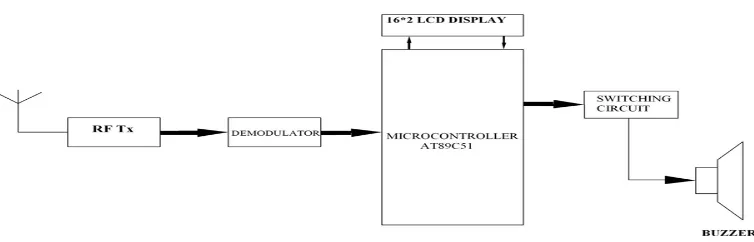
Fig. A & B Block diagram of the proposed system
III.WORKING/OPERATION
Microcontroller is the brain of the devised system the project consists of units 1) Equipment unit and 2) Technical unit. The equipment unit is inside the intensive care unit connected to the biomedical equipments. The technical unit is assumed to be with the technical staff in equipment unit the biomedical equipment is connected to the microcontroller via some relay and switching circuits. The equipment unit makes use of four different types of sensors, and voltage sensor. When short circuit in the equipment it will be detected by the short circuit sensor and the signal will be send to the microcontroller via monostable circuit. Monostable is a circuit which provides stable output from the fluctuating sensor input Likewise. When increase in equipment temperature is detected by the temperature sensor. The signal will be send to the microcontroller via the ADC Pin .When vibration of the equipment exceeds the threshold of the equipment. The vibration sensor will detect it and send the information to the microcontroller via the monostable. The same procedure is followed for the increase in the Voltage rating of the equipment. The entire sensing procedure is done simultaneous by the devised system module and displayed in the LCD display. If there is any abnormality in any of these parameters of the equipment, then the system will control the operation of the equipment to avoid accidents. Moreover, the signal information regarding the status of the equipment send to the technical unit by the microcontroller in equipment unit with the help of the rf transmitter via relay and buffer units. In the technical unit,the signal send from the equipment unit will be received by the rf receiver. The received signal will be fed to the microcontroller after demodulation. The microcontroller upon reception activates the buzzer with the help of the switching circuit and display the status of the equipment in the LCD Display.
IV.METHODOLOGY
The utmost intension of the project is to bring the automation in monitoring the biomedical equipment which hampers the patients in the intensive care unit. The devised project is designed in such a way that short circuit. Voltage over rating, overheating and vibration of the biomedical equipment in the ICU are detected and wanted to the technical unit, thereby avoiding the obstruction of the medical staff. The equipment unit inside the ICU is continuously monitoring by the designed module so that any sudden occurrence with variation which may lead to the abnormality of the equipment can be easily detected in an efficient way. The Biomedical Equipments used for the treatment will be terminated by the monitoring system from use if any capability is presumed. Whenever sudden fault in the treatment equipment module is sensed and acknowledged to the technical unit for the wellbeing of the patients.
V. HARDWARE REQUIRMENT
[image:3.612.117.494.133.254.2]B. Rf transmitter and receiver
C. Lcd display
D. Temperature and vibration sensor
E. Buffer and driver circuit
F. Monostable circuit
G. Power supply circuit
H. Replay and buzzer
VI.SOFTWAREREQUIRMENT
A. Embedded c
B. Mp lab ide
C. Keil micro vision 3
D. Power supply
It is the main part of the circuit; the circuit needs the 12V DC supply. But in our home 230 AC supply is available. So it has converted it to 12V DC and 5V DC by Rectifier circuit by regulator IC 7812 and 7805 respectively.
E. The Controlling Unit
This section is the heart of the system. The controller that has been used is the 89S52 which has a standard 8051 core of the very popular series of microcontroller series from Intel. This controller has 8kB of internal ROM and 256 bytes of RAM. The memory type is flash and thus is easily programmable. The flash chip takes only two to three seconds to be programmed.
The onboard flash memory guarantees an endurance of 1000 erase/program cycles. The version s52 is different from the c52 by the fact that it has a programming voltage of 5V as compared to 12V of that of the c51/52 devices. This controller is also in system programmable thus reducing the development time even further. The chip has 316 bit timers/ counters and 8 interrupt sources. 33MHz of maximum frequency is supported by this chip. Here the microcontroller has been connected in a standard fashion. The clock crystal of 12MHz has been connected between pins 18 and 19 which are the osc 1 and osc 2 pins of the controller. Further pins 18 and 19 are bypassed to ground via two 22pf capacitors which ensure that the internal oscillator is self starting. A power on reset network is also connected with the controller, in the form of a 10uF capacitor connected to the Vcc supply from pin 9 which is the reset pin of the controller. A 10 k resistor is grounded from the same pin. When the power to the circuit is switched on, the capacitor which initially has zero charge on it will take a high charging current. This charging current will flow to ground via the resistor thus generating a positive going short pulse across it. The time duration of this pulse is equal to the time constant of the RC network. Apart from this the system CPU can also be manually reset with the help of the reset switch that has been connected in parallel to the 10uF capacitor.
port 1 and Port 3 of the controller has been configured as the input port to which the output of the ADC is connected. The LCD has been connected to Port 0 and 3 lines of Port 2. The UART of the microcontroller have been divided between the GSM modem and GPS module. The RxD of the controller is connected to the output of the GPS module and the TxD of the controller has been connected to the data in of the GSM modem.
F. Properties of Rf
Electrical currents that oscillate at RF have special properties not shared by direct current signals. One such property is the ease with which it can ionize air to create a conductive path through air. This property is exploited by 'high frequency' units used in electric arc welding. Another special property is an electromagnetic force that drives the RF current to the surface of conductors, known as the skin effect. Another property is the ability to appear to flow through paths that contain insulating material, like the dielectric insulator of a capacitor. The degree of effect of these properties depends on the frequency of the signals.
G. Liquid Crystal Display
LCD stands for Liquid Crystal Display. LCD is finding wide spread use replacing LEDs (seven segment LEDs or other multi segment LEDs) because of the following reasons:
2) The ability to display numbers, characters and graphics. This is in contrast to LEDs, which are limited to numbers and a few characters.
3) Incorporation of a refreshing controller into the LCD, thereby relieving the CPU of the task of refreshing the LCD. In contrast, the LED must be refreshed by the CPU to keep displaying the data.
4) Ease of programming for characters and graphics. These components are “specialized” for being used with the microcontrollers, which means that they cannot be activated by standard IC circuits. They are used for writing different messages on a miniature
VII. APPLICATIONS
A. These are used in Industries and
B. Medical applications
VIII. FUTURE SCOPE
We handle this project, because medical equipment very costlier if any failure occurs the hole system should be replaced to avoid that we providing protection to the system to safeguard the medical equipment through electrical damage.
IX.CONCLUSION
Our results demonstrate that some multi-socket power lines, as well as some power cords were outside of the limits provided by the international protocols. Failures were quite limited mainly due to hospital policy regarding EST tests, which are performed on a yearly basis for all biomedical equipment. It is highly profound that equipment found to be out of the EST limits should be tested more often than a yearly basis and proceed with their replacement once they do not pass the tests.
X. ACKNOWLEDGEMENT
Existing system does not have any minimal protection which causes damage to the equipment to safeguard those from electrical parameters such as over voltage ,current and short circuit etc .and physical parameters such as vibration ,temperature protection etc provided in this project.
REFERENCES
[1] Rigel Medical co, Rigel 288 Hand-Held Electrical Medical Safety Analyser, Instruction Manual, Seaward Group, February 2007, Issue 1.0, Revision 1, Rigel
Medical U
[2] J. Bronzino, “Management of Medical Technology-A primer for Clinical Engineers”, Butterworth-Heinemann publisher, 1992
[3] Emergency Care and Research Institute, “Electrical Safety”, Health Devices Inspection and Preventive Maintenance System, ECRI, Philadelphia 1995
[4] Emona Intruments, Rigel Medical co, Rigel 288 Medical Safety Tester, AS/NZS3551, Biomedical Test Equipment Section, available in: e-Περιοδικό
Επιστήμης & Τεχνολογίας e-Journal of Science & Technology (e-JST) (3), 9, 2014 30
http://www.emona.com.au/Datasheets/17%20Electrical%20Safety%20&%20Biomedical%20Testing/Rigel288_AUS.pdf
[5] Hasan A. Al-. Nashash, “Electrical Safety of Medical Equipment”, School of Engineering, American University of Sharjah (AUS), available in:
http://faculty.ksu.edu.sa/MFALREZ/EBooks%20Library/Safety/Electrical%20Safety%20of%20Medical%20Equipment.pdf
[6] Ebme.co.uk, articles, Electrical Safety, available in: http://www.ebme.co.uk/arts/articles-electrical-safety.php