2
Assistant professor Electrical & Electronic Engineering EEE Malla Reddy Engineering College (Autonomous) Hyderabad, India
Abstract: This paper introduces a reduced rating star connected hybrid UPQC in distribution system for simulations of load current harmonics, voltage sag/swell and source neutral current. The star associated transformer has preference of utilizing least volt-ampere rating and subsequently, the centers are economical to fabricate and possess low space . The execution of proposed UPQC has been examined through broad reenactment contemplates.
From these examinations it is watched that the proposed totally repaid the source current harmonics, stack current harmonics, voltage sag/swell and neutral current
Keywords: UnifiedPowerQualityConditioner (UPQC); ditributed generator; fuzzy logic controller;matlab
I. INTRODUCTION
Electricity is utmost important for today’s fast growing world. The electricity consumption and demand rises randomly due to increase in manufacturing industrial load, domestics load and other loads. On behalf of the load forecasting the new power sector also installed to meet the load demand and future demand. However, some power losses occur during the transmission and distribution system. The conventional source like coal and nuclear is widely used in the electricity production, that source pollutes the environment severely. As well as, to prevent the increases of pollution by installing renewable energy sources in distribution network as Distributed Generator (DG). The DG is the small amount of power deliver to the distribution system such as diesel generator or other source. In this work the DG is used with solar and/or wind energyThe DG assumes a key part amid the pinnacle stack period or load surpasses the generation. Be that as it may, DG additionally remunerates the power quality issue all things considered. Power quality issues have been settled in past utilizing shunt aloof or dynamic channel. Of late, a few arrangements have been recommended and the late improvements in FACTS and power gadgets have opened new chances to apply control hardware based answers for control power systems problems. The use of power devices is the topic of current research and Unified Power Quality Conditioner (UPQC) is one of the most popular solutions used nowadays. The UPQC as classified in literature as simultaneous control device to control the active power and reactive power and it protects the sensitive load from major disturbances. The major disturbances occur in the distribution side are harmonics, voltage sags or swell, excessive neutral current. The UPQC comprises of combined operation of Static Synchronous Compensator (STATCOM) and Dynamic Voltage Restorer (DVR). The STATCOM is compensating the reactive power and harmonics in the load side and DVR mitigates the voltage sags or swell in the source side. From this proposed method the major disturbances are reduced and also the control voltage sag originating from the supply side .The reduced rating star connected transformer is minimum volt-ampere rating transformer which connected in parallel to the load and a LC filter is connected between the neutral of the star connected transformer.
II. UNIFIEDPOWERQUALITYCONDITIONER
A. Active Power Filter
Generally inactive channels were utilized for control quality change, the uninvolved channels comprises of mix of capacitor, inductor and resistor. Aloof channels are utilized for consonant separating. Inactive channels don't rely on the outer power source. It has numerous disadvantages, for example, it is bigger in measure, reverberation issue, impact of source impedance on execution, settled pay attributes. So active power filters (APF) came as exchange answer for inactive channels. active power channels expelsmusic and not has downsides, for example, inactive channels. Active power filters are classified as are shown in
Fig.Active power filter classifications
B. Basic Configuration Of Upqc
1) Series APF: In a transmission line arrangement APF is for the most part associated in arrangement. It is associated with the transmission line with the transformer. Arrangement APF is a voltage source inverter associated in arrangement with transmission line. It is utilized to repay or alleviate the issues which come because of voltage twists and voltage unbalances. The arrangement APF infuses a remunerating voltage with the goal that heap voltage will be flawlessly adjusted and directed. Controlling of arrangement inverter is finished by PWM methods. Here we utilized Hysteresis band PWM systems as it execution is simple. Additionally its reaction is quick. Its points of interest are clarified in consequent segments.
2) Shunt APF: In a transmission line shunt APF is for the most part associated in parallel. Shunt APF is utilized to make up for mutilations and sounds which are delivered because of current .Due to non-straight load there is music in stack current, so to keep source current totally sinusoidal and contortion free we utilizes Shunt APF. Shunt APF infuses remunerating current so the source current is totally sinusoidal and free from bends. Controlling of Shunt APF is finished by hysteresis band PWM systems. In hysteresis band PWM procedures yield current takes after the reference and current and is inside the settled hysteresis band. 3) Series Transformer: The vital voltage which is produced by arrangement APF with the goal that the voltage at stack side is
impeccably adjusted and controlled i.e. Sinusoidal is infused into the transmission line with the assistance of these transformers. The arrangement transformer turns proportion ought to be appropriate with the goal that infused voltage is reasonable to such an extent that it infuses a repaying voltage which will totally influence the heap to side voltage adjusted and furthermore it lessens the current moving through series inverter.
4) Low Pass Filter: Low pass channel is utilized at the yield of arrangement inverter with the goal that the high recurrence voltage parts are evacuated which is created because of exchanging of Voltage source inverter
Fig.Configuration of UPQC
C. Upqc Configuration
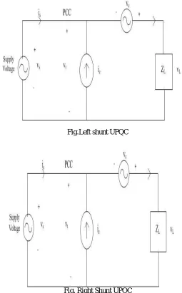
UPQC setup By and large UPQC can be arranged in two courses by associating unit to terminal voltage vt at PCC (purpose of basic coupling).
Left Shunt UPQC (fig 3.2):- In this the shunt compensator (ic) is set in left half of arrangement compensato (vc ). Right Shunt UPQC (fig 3.3):- In this shunt compensator (ic) is set in right half of arrangement compensator (vc)
Fig.Left shunt UPQC
[image:4.612.169.424.316.727.2]As shown in the fig Right shunt UPQC has better performance than left shunt UPQC so generally Right shunt UPQC is used.
D. Voltage And Current Variations
1) Voltage Magnitude Variation: The variety in voltage by littler range is called voltage magnitude variety. Increment and diminishing of the voltage magnitude
2) Voltage Frequency Variation:Like the magnitude, additionally the recurrence of the supply voltage isn't steady. Voltage recurrence variety is expected to unbalance amongst load and generation.We can call voltage frequency variation as "frequency deviation also
3) Current Magnitude Variation: On the heap side, the current isn't steady in magnitude. The variety in voltage extent is for the most part due to variety in current magnitude .
4) Current Phase Variation: In a perfect world, voltage and current waveforms are in phase. In that case the power factor of the heap rises to load equals, and the responsive power utilization is zero
5) Voltage and Current Unbalance: Unbalance, or three-phase unbalance, is the phenominal in a three-phase network, in which the RMS estimations of the voltages or the phase angle between back to back are not equivalent. The seriousness of the voltage unbalance in a three-phase network can be communicated in various ways, e.g.
These three severity indicators can be alluded to as "negative-arrangement imbalance," "magnitude unbalance," what's more, ''phase unbalance," separately. The essential source of voltage unbalance is lopsided load (this current unbalance). This can be due to an uneven spread of (single-phase) low-voltage customers over the three phases, but more commonly unbalance is due to a large single-phase load
E. Voltage Fluctuation
If the voltage magnitude varies, the power flow to equipment will also vary. In the event that the varieties are sufficiently vast or, on the other critical frequency, the execution of equipment can be influenced. The quick variety in voltage magnitude is called "voltage fluctuation," the visual phenomenon as perceived by our brain is called "light flicker”.
F. Harmonic Voltage Distortion
The voltage waveform is never precisely a solitary recurrence sine wave. This wonder is called "harmonic voltage distortion" or essentially "voltage distortion". When we accept a waveform to be occasional, it can be portrayed as a whole of sine waves with frequencies being products of the fundamental frequency. The non fundamental components are called "harmonic distortion."
G. Hormonic Current Distortion
The correlative marvel of consonant harmonic Voltage mutilation is harmonic current contortion. As symphonious voltagemutilation is fundamentally due to non sinusoidal load currents, harmonic voltage and current contortion are firmly connected. Consonant current bending requires over-rating of arrangement segments like transformers and links. As the arrangement protection increments with recurrence, a contorted current will cause a larger number of misfortunes than a sinusoidal current of the same rms esteem.
H. Inter Harmonic Voltage and Current Components:
Some equipment produces current components with a frequency which is not an integer multiple of the fundamental frequency. Ex: are cyclo converters and some types of heating controllers. These components of the current are referred to as "inter harmonic components." Their magnitude is ordinarily sufficiently little not to cause any issue, yet here and there they can energize unforeseen resonances between transformer inductances and capacitor banks.
I. Occasional Voltage Notching
Fig. Voltage magnitude events as utilized as a part of IEEE Std
III. FUZZY LOGIC CONTROLLER
Fuzzy logic is a creative innovation that improves technology plan with convenctional designing with engeneering. The utilization of fuzzy logic can go around the need for thorough numerical demonstrating. Fuzzy rationale is a genuine augmentation of customary logic, and fuzzy rationale controllers are a genuine expansion of straight control models. Consequently anything that was manufactured utilizing ordinary plan systems can be worked with fuzzy logic, and the other way around. Be that as it may, in various cases, traditional plan strategies would have ben excessively mind boggling and, as a rule, may demonstrate less difficult, speedier and more effective. The way to fruitful utilization of fuzzy logic is shrewd mix with ordinary systems. Additionally, a fuzzy framework is time-invariant and deterministic. In this manner any confirmation and solidness examination strategy can be utilized with fuzzy logic, as well.
IV. SIMULATION MODELS AND RESULTS
controlling
Discrete, Ts = 5e-005 s.
powergui Wind (m/s) Trip m A B C m wind (m/s) trip A B C Wind Turbine Induction Generator (Phasor Type) A1 B1 C1 A2 B2 C2 UPQC Timer co
mA B C
a b c Three-Phase Breaker Vabc IabcA B C a b c Three-Phase V-I Measurement2 A B C a b c Three-Phase V-I Measurement1 Vabc IabcA B C a b c Three-Phase V-I Measurement
A B C
Three-Phase Series RLC Load1
A B C
Three-Phase Series RLC Load A B C A B C
Three-Phase Series RLC Branch3
A B C A B C Three-Phase Series RLC Branch2
A B C A B C Three-Phase Series RLC Branch1 A B C A B C Three-Phase Series RLC Branch
[image:6.612.111.475.442.704.2]N A B C Three-Phase Programmable Voltage Source Switch Sine Wave Scope4 Scope3 Scope2 Scope1 Scope wind1 [Trip_WT1] 12 Constant Clock Add
A B C
170 kvar A B C A B C
1 km line 1
A B C a b c n2 0.69/33e3 630KVA
dq0 sin_cos abc dq0_to_abc Transformation z 1 Unit Delay1 z 1 Unit Delay Switch1 Switch PID(s) PID Controller shp Goto [Vsabc] [Vsabc] [Isabc] UDC Fo=200Hz Discrete 2nd-Order Filter1 Fo=200Hz Discrete 2nd-Order Filter UrefPulses Discrete PWM Generator PI PI Vabc(pu) Freq wt Sin_Cos 4000 0 Constant Clock Add2 Add1 Add Vabc Iabc PQ 3-phase Instantaneous Active & Reactive Power
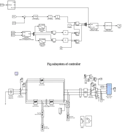
Fig.subsystem of controller
controlling
Discrete, Ts = 5e-005 s.
powergui Wind (m/s) Trip m A B C m wind (m/s) trip A B C Wind Turbine Induction Generator (Phasor Type) A1 B1 C1 A2 B2 C2 UPQC Timer c o
mA B C ab c
Three-Phase Breaker Vabc IabcA B C a b c Three-Phase V-I Measurement2 A B C a b c Three-Phase V-I Measurement1 Vabc IabcA B C a b c Three-Phase V-I Measurement
A B C
Three-Phase Series RLC Load1
A B C
Three-Phase Series RLC Load
A B C A B C
Three-Phase Series RLC Branch3
A B C A B C Three-Phase Series RLC Branch2
A B C A B C Three-Phase Series RLC Branch1 A B C A B C Three-Phase Series RLC Branch
N A B C Three-Phase Programmable Voltage Source Switch Sine Wave Scope4 Scope3 Scope2 Scope1 Scope wind1 [Trip_WT1] 12 Constant Clock Add
A B C
170 kvar A B C A B C
1 km line 1 A B C a b c n2 0.69/33e3 630KVA
Fig. simulation model with fuzzy logic controller
dq0 sin_cos abc dq0_to_abc Transformation z 1 Unit Delay1 z 1 Unit Delay Switch1 Switch shp Goto Fuzzy Logic Controller [Vsabc] [Vsabc] [Isabc] UDC Fo=200Hz Discrete 2nd-Order Filter1 Fo=200Hz Discrete 2nd-Order Filter UrefPulses Discrete
PWM Generator
PI PI Vabc(pu) Freq wt Sin_Cos du/dt Derivative 4000 0 Constant Clock Add2 Add1 Add Vabc Iabc PQ 3-phase Instantaneous Active & Reactive Power
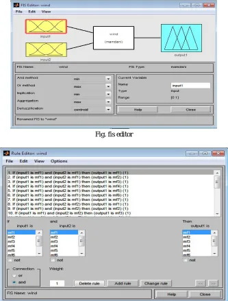
Fig. fis editor
Fig. simulation model with neural network controller
[image:9.612.154.453.298.495.2]Fig.THD for voltage for without upqc
A. Comparision Of Thd Without And With Upqc
Without UPQC With UPQC
Values THD % Values THD % I Source 0.045 A 25.6 2.45 10.32 V Source 360 V 40.73 360 V 37.88 V Load 360 V 0.15 360 V 0.6 I Load 0.035 A 0.9 2.45 0.31
B. Comparision Of Thd With Upqc And Different Controllers With UPQC
PID FLC NN
I Source 25.6 11.2 8.6
V Source 40.73 32.1 15.2
V Load 0.15 0.12 0.9
I Load 0.9 0.85 0.35
V. CONCLUSION
This paper presents a reduced rating star connected hybrid UPQC in distribution systems for simultaneous compensation of load current harmonics, voltage sag/swell and source neutral current. The star connected transformer has an advantage of using minimum volt-ampere rating and consequently, the cores are economical to build and occupy low space. The performance of proposed UPQC has been investigated through extensive simulation studies. From these studies it is observed that the proposed scheme completely compensated the source current harmonics, load current harmonics, voltage sag/swell and neutral current
REFERENCES.
[1] Sankaran, Power Quality, Boca Raton: CRC Press, (2002) p:202.
[2] R.A.Walling, R.Saint, R.C.Dugan, J.Burke and I.A.Kojovic, “Summery of Distributed Resources Impack on Power Delivery Systems”, IEEE Trans, Power Delivery, Vol.23, No:3, (July 2008), pp:1636-1644.
[3] H.Akagi, and H.Fujita, “The unified power quality conditioner. The integration of series and shunt-active filters,” IEEE Trans. Power Electron., Vol.13, No:2, (Mar, 1998) pp: 315-322. “A new power line conditional for harmonic compensation in power systems,” IEEE Trans. Power Del., Vol.10, No.3, (Jul, 1995) pp:1570-1575.
[4] H.Akagi, E.H.Watanabe and M.Aredes, Instantaneous Power Theory and Applications to Power Conditioning. Wiley-IEEE Press. (April 2007)
[5] D.Graovac, A.Katic, and A.Rufer, “Power Quality Problems Compensation with Universal Power Quality Conditioning System, IEEE Transaction on Power Delivery, Vol.22, No.2. (2007)
[6] B.Han, B.Bae, H.Kim, and S.Back, “Combined Operation of Unified Power Quality Conditioner with Distributed Generation,” IEEE Transaction on Power Delivery, Vol.21, no.1, (2006) pp.330-338.
[7] M.Aredes, “A combined series and shunt active power filter,” in Proc. IEEE/KTH Stockholm Power Tech Conf., Stockholm, Sweden, (June 1995), pp.18-22. [8] Y.Chen, X.Zha, and J.Wang, “Unified Power Quality conditioner (UPQC): The theory, modeling and application,” Proc. Power System Techlogy Powr Con
Int. Conf., Vol.3, (2000), pp1329-1333.
[9] F.Z. Peng, J.W. McKeever, and D.J. Adams, “A power line conditioner using cascade multilevel inverters for distribution systems,” IEEE Trans.Ind.Appl., vol.34, no.6, Nov./Dec. 1998, pp.1293-1298,