A Study on Driving Stability of Bus Using
Computational Fluid Dynamics (CFD)
Girmachew Ashagrie1, Ramesh Babu Nallamothu2, Anantha Kamal Nallamothu3 , Seshu Kishan Nallamothu4
1
School of Mechanical and Automotive Engineering, Automotive Engineering Department, Dilla University. Dilla, Ethiopia.
2
Mechanical and Vehicle Engineering Department, Adama Science and Technology University, Adama, Ethiopia.
3
Mechanical Engineering Department, Vellore Institute of Technology, Vellore, India.
4
Automobile Engineering Department, SRM University. Chennai, India.
Abstract: The rules of aerodynamics explain how the drag force consumes energy which indirectly fuel also it explains how it will affect the stability of the vehicle. Many researchers make their study on this area. Recently in developing countries too many traffic accidents are happening and taking to many lives. The worst thing is the total number of vehicles in these countries is too less, when it is compared to the developed countries. The reason for these accidents is may not be only due to the road condition or due to the failure of vehicle parts, it may be aerodynamic effect. So in this paper it is been tried to study the effect of aerodynamics on driving stability of the bus being driven.
Keywords: directional stability, yawing, rolling, pitching moments, resistance moments
I. INTRODUCTION
The importance of aerodynamics to several type car bodies model needs a development of drag and lift estimation to know how much the car performance on the road against air resistance beside to improve the stability, reducing noise and fuel consumption. Automobile handling and vehicle handling are descriptions of the way a wheeled vehicle responds and reacts to the antics of a driver, as well as how it moves along a track or road. It is commonly judged by how a vehicle preforms particularly during cornering, acceleration, and braking as well as on the vehicle's directional stability when moving in steady state condition. Directional stability is stability of a moving body or vehicle about an axis which is perpendicular to its direction of motion. Stability of a vehicle concerns itself with the tendency of a vehicle to return to its original direction in relation to the oncoming medium (water, air, road surface, etc.) when disturbed (rotated) away from that original direction. If a vehicle is directionally stable, a restoring moment is produced which is in a direction opposite to the rotational disturbance. This "pushes" the vehicle (in rotation) so as to return it to the original orientation, thus tending to keep the vehicle oriented in the original direction.
There are three mechanisms by which the aerodynamic forces and moments have major influences on stability. The first mechanism is in directly influencing the directional stability through the substantial aerodynamic side forces and yaw moments on the vehicle body: these forces and moments arise when the vehicle body acts at a small angle of attack relative to the straight ahead position. The net resulting aerodynamic side force and yaw moment are sometimes combined and referred to as a single force acting at the aerodynamic center of pressure inside view.
Directional stability is associated with this center of pressure being aft of the vehicle mass center (or 'center of gravity'). The extent to which the center of pressure is aft of the center of gravity is often referred to as the 'aerodynamic static margin'.
The second mechanism is associated with the wheels. For the non-steered wheels which may be directly in the airstream or housed within fairings, their aerodynamics simply add on to the body terms and are therefore included directly. However, steered wheels are capable of generating additional lateral forces by operating at an angle to the vehicle body and hence a different angle of attack relative to the airstream. They behave in a similar way to the wheel/ground system in generating a lateral force in response to a slip angle. The effectiveness of this mechanism depends very much on how much the steered wheels are in the airstream rather than hidden in the body.The third mechanism is an indirect route. As the speed varies the aerodynamic down force and pitch moment vary, and these in turn control the wheel loads, which in turn then influence their ability to generate lateral forces at the wheel ground contact region. On the Car it is proposed to manage these wheel loads throughout an entire run using programmable winglets over the front and rear axles.
II. LITERATUREREVIEW
The dynamic stability of a vehicle depends on various maneuvering features, such as traction, braking, and cornering (Allen et al., 1990, 1991; Allen and Rosenthal, 1993). Two types of vehicle motion are important factors for achieving dynamic stability: roll and yaw. Excessive roll during sharp cornering often causes a vehicle to overturn; the major problem of roll stability is the prevention of rollover. Yaw may occur in any driving situation. In traction and braking, the main yaw stability issue is the prevention of any type of yaw motion, whereas in cornering, the primary concern is controlling the magnitude of the yaw rate.
The most popular method for analyzing yaw during cornering is in terms of steer tendencies, categorized as neutral-steer, under-steer, and over-steer. The steer tendency is determined by the direction of the yaw moment, which is induced by lateral forces generated at each tire. The idea originated in the linear analysis technique applied to cornering maneuvers with less than 0.3 g of lateral acceleration. This technique was borrowed from aerospace dynamics and uses a linearized vehicle model to obtain the sensitivity equations of the system states.
The steer tendencies can be derived from these equations. The linear analysis technique is capable of providing useful information in the neighborhood of a specific operating point and hence is appropriate for studying normal driving situations but not critical ones. During critical cornering, the determination of whether a vehicle is in the stable region is the key factor for analyzing yaw stability. In this situation, the stability potential of a vehicle is also significant. The size and pattern of its stability region can be used as the criteria to analyze the stability of a vehicle during critical cornering (Ko et al., 2002).
Dynamic stability is a very important factor in vehicle design and control because it has a strong influence on overall vehicle safety. The more dynamically stable a vehicle is, the smaller the likelihood that the driver will lose control of it. As a nonlinear dynamical system, every vehicle has a definite stability region. Most of the existing studies (Gillespie, 1992; Milliken and Milliken, 1995) on vehicle yaw stability focus on the concept of steer tendency (neutral-steer, under-steer, and over-steer). This concept was derived from the force analysis of a linearized vehicle model with two degrees of freedom and is used as a key parameter in fine-tuning the handling characteristics of a vehicle. The linear analysis technique was originally introduced in connection with the stability derivative in aerospace dynamics.
Zeng et al.(2006) proposed a dynamic model for lateral and yaw motions with 10 degrees of freedom. They showed that linearized models are useful for studying vehicle parameters, such as the under-steer gradient, steering sensitivity, and roll and sideslip gradients. The results are still applicable in the linear range when the lateral acceleration is less than 0.3 g.
This study presents the overall driving stability of a high speed bus considers the rolling and yawing effect of the drag induced at high speed running due to the point of difference between the center of gravity and center of pressure. The model of the bus is taken from the Sleam bus SC. known as Youtong bus. The geometry is generated using CATIA V20 software. And the simulation test is preceded using CFD software.
III.ANALYTICALPROCEDURES
A. CFD simulation
Rotating moment generated on the vehicle body due to the difference in location between C.P and C.G. its result obtained from CFD simulation. I have been conducting six tests on given bus model; the rotating moment value in three axes’ is not significantly varying.
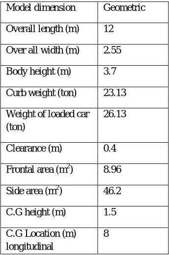
[image:3.612.133.476.559.721.2]At first the geometry of the bus has been taken from Youtong Bus and the specification is tabulated as follows.
Table 1 specification of the bus
Model dimension Geometric
Overall length (m) 12
Over all width (m) 2.55
Body height (m) 3.7
Curb weight (ton) 23.13
Weight of loaded car (ton)
26.13
Clearance (m) 0.4
Frontal area (m2) 8.96
Side area (m2) 46.2
C.G height (m) 1.5
C.G Location (m) longitudinal
8
Setting the software boundary conditions and prepare for test using the following conditions.
B. Domain size
[image:4.612.220.392.89.349.2]X: 252m Y: 62.55m Z: 30M Runing conditions and boundaries
Table 2 Simulation boundary conditions
Inlet 1 Velocity boundery = 120km/hr
Inlet 2 Velocity boundery for side-wind
Outlet 1 Pressure boundery with fully deloped condition
Outlet 2 Pressure boundery with fully deloped condition
Surface of model vehicle
No slip condition
Low wall Slip boundery with inlet air velocity
Radius of gyration 100m, 200m, 300m
[image:4.612.73.480.415.722.2]Fig.3 CFD simulation mesh genration
Fig.4 simulation result of velocity contor.
Fig.5 simulation result of pressuer contor.
C. Centrifugal force and moment
Centrifugal force: - and this force forms a Centrifugal moment
and at 120km/h
and
and at 120km/h
and
and
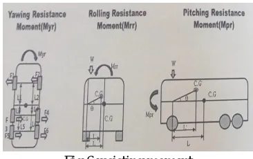
[image:6.612.219.402.109.224.2]D. Resisting moment generated on the vehicle body against the rotating momentums
Fig 6 resisting moment
Fig. 7 yutong bus model generated on CATIA V20
E. Yawing resisting moment
Table 3 average values of tire friction coefficient
.
Yawing resisting moment assume running on dry asphalt road surface. And take average tire friction coefficient
0.85. L1 = 2.5m and L2 = 5.5m
Take counter clockwise positive (CCW)
The weight of force on c.g is
The normal force on each tire is ,
weight on each rear tire.
Fig 8 free body diagram
Yaw resisting force is obtained as this on the front tire. On the rear
Yawing resisting moment;
[image:7.612.231.393.287.401.2]Rolling resistance moment ( ).
Fig. 9 rolling resistance moment
Tire section width is 285mm or 0.285m
Roll resisting force acting at the center of tire or 0.852/2 = 0.1425m so, L = track width of bus minus 0.1425m i.e. 2.55m – 0.1425m = 1.1325m.
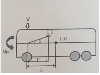
F. Pitching resisting moment ( ).
Fig. 10 pitching resisting moment
For this case L = 5.5m from C.G location to front tire center.
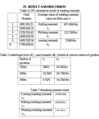
[image:7.612.224.399.507.639.2]IV.RESULTANDDISCUSSION
Table 4 CFD simulation result of rotating moment Grid
Number
Average value of rotating moment value on three axis’s
1 80X35X25 Rolling moment 267.45kNm,
2 100X45X35
3 125X55X45 Pitching moment 212.7kNm,
4 140X65X50
5 160X76X56 yawing moment 159kNm,
[image:8.612.156.491.60.464.2]6 179X83X62
Table 5 centrifugal force ( and moment ( results at various radius of gyration
Radius of gyration
100m 29kN 43.5kNm
200m 14.5kN 24.75kNm
300m 9.7kN 14.55kNm
Table 7 Resisting moment result
Yawing resisting moment m
Rolling resisting moment
Pitching resisting moment
A. Result comparison.
The moment induced due to the centrifugal force of the vehicle tend to roll the vehicle. So we can sum up or subtract this moment to or from the rolling moments. In this case it is been added to the rolling moment.
Table 6 combined centrifugal moment ( and Rotating rolling moment .
Radius of gyration
Rotating rolling moment
100m 29kN 43.5kNm 310.95 kNm
200m 14.5kN 21.75kNm 289.2kNm
300m 9.7kN 14.55kNm 282kNm
[image:8.612.177.445.663.733.2]Since the resistance moment is been calculated from the above portion of this paper now we can compare it with the rolling moment of the vehicle in order to say the vehicle is stable or unstable.
Table 7 comparison of rolling moment with resistance moment Radius of
gyration
Rolling moment Rolling resistance
moment
100m 310.95 kNm
200m 289.2kNm
Now we can see that the vehicle runs at 120 km/h and if it turns with this speed a curve of radius gyration 100m automatically it will roll over because the resistance moment is less than the rolling moment. But with the same speed if the radius of gyration is 200m it may be stable and can make a turn but for 300m radius it is completely safe.
As we can see from the results if the vehicle makes no turn in either right or left direction the rolling moment is 267.45 kNm and with this moment there is no chance of rolling over because the resistance moment is 290.3 kNm.
Similarly the effect of yawing moment can be compared with yawing resistance moment as follows.
But in this case the effect of centrifugal force may not be added because it is with the same axis with radius of gyration which makes it perpendicular to the yawing moment.
Table 8 comparison of yawing moment to yawing resistance moment
Yawing moment Yawing resistance moment
159kNm
It is the resistance moment which is higher than the yawing moment so that the vehicle could not be suffers for stability problem due to yawing. Also in case of pitching the pitching moment is greater than the resistance moment but when we see the effect of pitching on stability it won’t affect anything. Of course there will be a problem caused by pitching if the road is not smooth pitching will create steer ability problem because of its gyroscopic effect.
V. CONCLUSION
The analysis of driving stability can be done by considering different conditions and body parts and starting from the tire, the body of the vehicle, accessories of the vehicle, weather conditions, road conditions and others. In this paper it is been tried to understand the effect of aerodynamics on a vehicle driving stability which mainly focus on rolling and yawing moments caused by the forward drag side wind. The total moments (yawing, rolling and pitching) of the given bus model running at 120 km/h is been taken from CFD test result and its centrifugal moment induced while the vehicle make a turn at different radius of gyration has been calculated and the effect is considered. In this study at 100m radius of gyration with 120km/h rolling moment is greater than the rolling resistance moments so the vehicle will roll over in this case it is unstable. And for radius gyration 200m the rolling resistance moment is slightly greater than the rolling moment so we can say that it is stable but if a little increment in rolling moment will make it unstable. Whereas for the vehicle running with radius of gyration 300m. It is completely stable in rolling. For yawing as it is compared the yawing resistance moment is greater than that of the yawing moment we can say that the vehicle is stable.
REFERENCES
[1] Y. E. KO1) and C. K. SONG2)* (2009). Vehicle Modeling With Nonlinear Tires For Vehicle Stability Analysis. International Journal of Automotive Technology, Vol. 11, No. 3, pp. 339−344 (2010).
[2] Allen, R. W., Szostak, H. T., Rosenthal, T. J. and Klyde, D. H. (1990). Field testing and computer simulation analysis of ground vehicle dynamic stability. SAE Paper No. 900127.
[3] Allen, R. W., Szostak, H. T., Rosenthal, T. J., Klyde, D. H. and Owens, K. J. (1991). Characteristics influencing ground vehicle lateral/directional dynamic stability. SAE Paper No. 910234 .
[4] Allen, R. W. and Rosenthal, T. J. (1993). Computer simulation analysis of safety critical maneuvers for assessing ground vehicle dynamic stability. SAE Paper No. 930760.
[5] Ko, Y. E. and Lee, J. M. (2002). Estimation of the stability region of a vehicle in plane motion using a topological approach. Int. J. Vehicle Design 30, 3, 181– 192.
[6] Gillespie, T. D. (1992). Fundamentals of Vehicle Dynamics. Society of Automotive Engineers. Warrendale. PA.
[7] Milliken, W. F. and Milliken, D. L. (1995). Race Car Vehicle Dynamics. Society of Automotive Engineers. Warrendale. PA . [8] Adrien Becot. Aerodynamic force modification via base roughness. Master‟s thesis, Cranfield University, 2012.
[9] Ahmad Kamal Matamin, "Aerodynamic Study of a Coach Using Computational Fluid Dynamic(CFD) Technique", August 2006.
[10] A. Muthuvel, M. K. Murthi, N. P. Sachin, Vinay M. Koshy, S. Sakthi, and E.Selvakumar, "Aerodynamic Exterior Body Design of Bus", International Journal of Scientific & Engineering Research, ISSN2229-5518, Vol. 4, Issue 7, pp. 2453-2457, July-2013.
[11] Hucko,W.H Emmelmann. H.J (1977) “Aerodynamiche Formoptimierung,ein weg zur steigerung der wirtschsftlichkeit von nutzfahrzeugen,” Series.12, NO.31 1977.
[14] Solomon Neway, Ramesh Babu Nallamothu, Seshu Kishan Nallamothu, Anantha Kamal Nallamothu"Investigation on Pollution Caused by Gasoline and Diesel fuelled Vehicles", International Journal of Engineering Trends and Technology (IJETT), V36(7),376-381 June 2016. ISSN:2231-5381. www.ijettjournal.org. published by seventh sense research group.