Technology (IJRASET)
Investigation Of Heat Transfer Enhancement In
The Flat Plate Solar Collector Using Nano Fluid
Varsha Sahu1, Mr. Vinay Kumar2, Mr. Shashank Mishra3
1
Student of Thermal Engineering, S.S.G.I (S.S.T.C)
2
Assistant Professor, Mechanical Engineering Department, S.S.G.I (S.S.T.C)
3
Assistant Professor, Mechanical Engineering Department, S.S.G.I (S.S.T.C)
Abstract:-This research presents overview about Nano fluid with solar collector applications, an existing emerging class of heat transfer fluid, in terms of barriers, future research and environmental challenges. Nano fluids are used to increase the performance of many thermal engineering systems.
By referring the experimental investigation [55], the main objective is to prepare a CFD model and using Nano fluid as flowing fluid, which investigate the efficiency of square flat plate solar collector and enhancement in heat transfer with the use of different Nano fluid as compare to water . Therefore we are adopting the simulation method to resolve the problem of Use of Nano fluid in the flat plate collector and to get the improved results by using computational fluid analysis in ANSYS 15.0 by FLUID FLOW FLUENT solver.
The center point was to evaluate the use of different Nano fluid in the developed region of the tube flow containing water + Nano fluid (Al203 and Ti2O, CuO, and SiO2) on heat transfer characteristics. It was perceived that all Nano fluids (Al203 and Ti2O, CuO, and SiO2) revealed higher heat transfer characteristics than that of the base fluid (water). Furthermore the Nusselt number and the surface heat transfer coefficient is higher for CuO + Water Nano fluid as compare to other Nano fluid which are investigated on the basis of Reynolds and Nusselt number. Moreover we investigate the heat transfer characteristics with different pipe diameter for the (CuO + water) Nano fluid.
Keywords: CAD model of flat plate solar collector, Nano fluid, Reynolds number, Nusselt number, heat transfer.
I. INTRODUCTION
A. Nanofluids
Nanofluids demote to a solid-liquid mixture or suspensions produced by dispersing tiny metallic or nonmetallic solid Nano particles in liquids. Nanofluids are a new class of fluids engineered by dispersing nanometer sized materials (Nano-particles, Nano-fibers, Nano-tubes, Nano-wires and Nano-rods) in base fluids. The size of nanoparticles (usually less than 100nm) in liquids mixture gives them the ability to interact with liquids at the molecular level and so conduct heat better than today’s heat transfer fluids depending on Nano particles. Nanofluids can display enhanced heat transfer because of the combination of convection & conduction and also an additional energy transfer through γ-particles dynamics and collisions. Metallic nanofluids have been found to possess enhanced thermo physical properties such as thermal conductivity, thermal diffusivity, viscosity and convective heat transfer coefficients compared to those of base fluids like oil or water. In current years, nanofluids established greater potential in many fields like solar collector and solar thermal storage. Even though some review articles involving the progress of nanofluids investigations were published in the past several years [14, 15], most of the reviews are concerned with the experimental and theoretical studies of the thermo physical properties or the convective heat transfer of nanofluids.
B. Classification of Nanofluids
Technology (IJRASET)
II. LITERATURE SURVEY
A. Application of Nanofluids in Solar Collectors
The previous researchers review by Omidmahian et.al [17] gives a noble awareness about enhanced the efficiency and performance of the solar thermal system, solar water heater, thermal energy storage, solar cells and solar stills, there is a very limited number of research works in the area of solar collectors augmented with nanofluids.
Basically, low temperature nanofluids based direct absorption solar collectors (DASC) were investigated theoretically by Tyagi et.al [18]. They studied Al2O3 water based nanofluids was used for the investigation where the particle volume fraction (0.1% to 5%) influenced the collectors efficiency. Significant increase in the collector’s efficiency was observed not only varying the particles volume fraction, but also the glass cover transitivity & collector height. It is reported, efficiency increases by 8% for volume fraction ranging from 0.8% to 1.6% and the effect of size of Nano particles in increasing efficiency is marginal.
Taylor et.al [19] investigated experimentally, by using graphite/ terminal VP-1 nanofluids for 10- 100MW solar power tower collectors and observed potential improvement in efficiency. Theoretically 10% in efficiency can be observed when compared with the conventional solar collectors, when using solar concentration ratio of 10-1000. Experimental results shown that 5-10% increase in efficiency can be achieved while using the nanofluids in the receiver section. The authors also estimated that $3.5 million/year more revenue can be attained by proper implementation.
Li et.al [20] carried out studies similar to Taylor et.al [19] by using three different nanofluids (Al2O3/water, ZnO/water &MgO/water) on the tubular solar collectors. The performance results showed that 95% of the incoming sunlight can be absorbed effectively while using the Nano fluid of volume fraction less than 10 ppm.
Efficiency of the flat plate solar collector was experimentally investigated by Yousefi et.al [21] using Al2O3 /water Nano fluid with weight concentration of 0.2% & 0.4% and particle size of 15nm. The investigation was carried out with Triton X-100 as surfactant as well as without it. The results presented 28.3% increase in the efficiency is obtained with 0.2% weight fraction Nano fluid. Additionally 15.63% increase in efficiency is observed by increasing mass flow rate and using the surfactant. The researchers further investigated MWCNT/water nanofluids in the flat plate solar collector with 0.2% weight fraction, pH of 3.5, 6.5 & 9.5 respectively and Triton X-100 as surfactant by [22]. The results revealed that the surfactant influences the efficiency and pH of isoelectric point enhances the efficiency of the collector. Finally, the review of all existing experimental and numerical data results for the prediction of the solar collector.
Khullar et.al [23] investigated aluminum based Nano fluid both theoretically & experimentally on concentrating parabolic solar collector (CPSC). The aluminum based Nano particles were suspended in Terminal VP-1 base fluid with 0.05% volume concentration. The results were compared with the conventional concentric parabolic solar collector which reveals that increase in 5-10% of thermal efficiency was observed.
Currently, Titan C.Paul,et.al [24] summarized their experimental investigation on next generation solar collectors (CSP) using NEILS ( Nanoparticle Enhanced Ionic Liquids) as working fluids their results revealed that thermal conductivity was enhanced around 5% depending on the base fluid and ionic concentration. The heat capacity of Nano fluid using Al2O3 Nano particles was enhanced by 23% and 26% for nanofluids using silica Nano particles and similarly 20% enhancement in convective heat transfer capacity was also observed.
Nanofluids (CNT, Graphite & Silver) based direct absorption solar collectors (DASC) were studied experimentally and numerically by Otanicar et.al [25], the effects of nanofluids on the efficiency improvement up to 5% were observed, using nanofluids as the absorption medium. The author compared the experimental data’s with their respective numerical data. The results revealed that 3% efficiency increase can be achieved by using graphite nanoparticles of size 30nm, 5% efficiency increase can be achieved by using silver nanoparticles of size 20 to 40nm, where a 6% efficiency enhancement was observed when the particle size is halved.
Also light heat conversion characteristics of two different nanofluids (TiO2/water & CNT/water) were studied experimentally using vacuum tube solar collector in different weather patterns by He et.al [26]. The result shows excellent light heat conversion characteristics while using CNT/water nanofluids with 0.5% weight concentration. However, the temperature of CNT/water Nano fluid is observed to be greater, which shows the CNT/water Nano fluid is more suitable for vacuum tube solar collector application comparatively.
Technology (IJRASET)
III. SIMULATION METHODOLOGY
A. CFD Simulation method
[image:4.612.93.259.161.314.2]The ANSYS 15.0 finite element program was used for analyzing Pipe flow. The equation of motion of Pipe is solved using FEV tool (ANSYS 15.0 – Fluid flow Fluent) as the equation of motion for a Pipe is difficult to visualize therefore some FEV tool is the only solution method for analyzing hydrodynamic characteristics. To find out the Reynolds number for different Nano fluid we are adopting Reynolds stress model for CFD simulation.
Figure: CFD Simulation Sequences.
The geometry and mesh was created by using ANSYS FLUENT 15.0 .The FLUENT is an integrated postprocessor for CFD analysis. The sequences of fluent steps are shown in Figure 4.1.
B. 4.4.1 Step 1 -Geometry generation
[image:4.612.190.422.428.642.2]First of all in ANSYS 15.0 we choose Fluent in which we first draw the geometry with the help of ANSYS geometric tools. The key points were first created and then line and spline segments were formed. The lines were combined to create an area. Finally, this area was extruded and we modeled the square flat plate collector.
Figure CAD model of flat plate solar collector.
Figure shows the actual model of flat plate collector, since we are only dealing with the pipe flow and its temperature gain by solar radiation therefore only considering the pipe and pipe flow, therefore the geometry was taken for the simulation for different Nano fluid like SiO2 + Water as Case 1, AL2O3 + Water as Case 2, Ti2O + Water as Case 3& CuO + water as Case 4 was shown below in figure below.
CFD SIMULATION
1- GEOMETRY GENRATION
2- MESHING
3- BOUNDARY CONDITIONS
4- SETUP
5- SOLUTION
Technology (IJRASET)
Figure: CAD model for 5.1 mm pipe diameter & for different Nano fluid.
Figure: 2D diagram for 5.1 mm pipe diameter & for different Nano fluid
Figure shows the 2D diagram of geometry in which we take 5.1mm diameter of pipe for different Nano fluid like SiO2 + Water as
Case 1, AL2O3 + Water as Case 2, Ti2O + Water as Case 3& CuO + water as Case 4 and all other dimensions were referred from experimental diagram [55].
B. 4.4.2 Step 2 -Meshing
[image:5.612.195.422.250.397.2]For this purpose, we switch to meshing where we choose the required meshing parameters.
Figure: Mesh file for problem domain
Figure shows the mesh file for problem domain, in this case we have chosen meshing parameters as sizing parameters 1mm and created elements and nodes. There are 629865 element and 783888 nodes in the radial direction with a size ratio of 1 mm from the center to the wall.
C. 4.4.3 Step 3 -Boundary conditions
[image:5.612.205.404.500.619.2]Technology (IJRASET)
adopted and for SiO2 + Water Nano fluid the experimental data [55] was adopted for simulation.
D. 4.4.4 Step 4 -Setup for simulation
Now, we go to Setup of Fluent in which we check that whether energy equation is on, next we check the materials, which is SiO2 + Water termed as Case 1, AL2O3+ Water termed as Case 2, Ti2O+ Water termed as Case 3& CuO+ water termed as Case 4
respectively and 2 % volume concentration for Nano fluid was adopted for maximum value of Reynolds number. By providing inlet velocity as 1 m/s and diameter of pipe 5.1 mm constant for different Nano fluid which is same as experimental. Now we select the best case (i.e. case 4) in which we get the enhanced heat transfer result for further investigation.
4.4.5 Step 5 – Solution
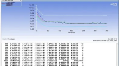
Figure: Solution converged for 5.1 mm pipe diameter & for different Nano fluid.
Figure shows the value of iteration for converged result for different Nano fluid. For that now, we will calculate or iterate the problem and for this problem we chose 300 iterations to converge the result and then we selected the graphs and plots window where we checked the contours of different graphs for different Nano fluid like SiO2 + Water as Case 1, AL2O3 + Water as Case 2, Ti2O + Water as Case 3& CuO + water as Case 4.
IV.RESULTSANDDISCUSSIONS
A. Validation with experimental data with present CFD simulation
Effect of the incident solar radiation on the collector efficiency when an experimental SiO2/water Nano fluid and water were used as coolants by referring experimental data [55] and influence of the same incident solar radiation on the Nano fluid (SiO2 + Water) by using CFD simulation i.e. present analysis in ANSYS 15.0 (Fluid flow FLUENT) are as follows.
Figure: Validation with experimental data with present CFD simulation of Case-1.
[image:6.612.208.404.193.302.2] [image:6.612.201.409.463.647.2]Technology (IJRASET)
fluid the data used were taken from the experiment result of A.Noghrehabadi et al. We compare the present CFD analysis and experimental data with the help of MATLAB (R 2011) simulation and plot the graph in between incident solar radiation and efficiency of flat plate collector in which we obtained efficiency for Case 1 which is 0.601 % and the experimental [55] efficiency of Nano fluid is 0.598 % and for water it is 0.57 % .
[image:7.612.35.580.196.361.2]Hence we can clearly said that the result obtained from CFD simulation for 5.1 mm diameter for Sio2 + water Nano fluid (i.e. Case 1) is in good agreement with experimental results of A.Noghrehabadi et al. and we obtained the increase value of efficiency, which is directly proportional to heat transfer.
Table 2: Percentage Deviation in Efficiency of Present CFD analysis for Nano fluid (SiO2+ water) compare with Experimental data of Water by referring [55]
Experimental data of Water by referring [55] Present CFD analysis for Nano fluid for (SiO2+ water ) Case 1 % Deviation in Efficiency
Incident solar radiation Efficiency Efficiency
361.148 0.56 0.56 1.058652
425.314 0.56 0.57 2.145095
514.952 0.56 0.58 2.934216
590.815 0.57 0.59 3.314828
649.406 0.57 0.59 3.907689
705.229 0.57 0.59 4.384011
814.118 0.57 0.60 4.916559
838.928 0.57 0.60 4.888503
918.147 0.57 0.60 5.085891
925.05 0.57 0.60 5.037032
From table 2 we obtained the value of 5% deviation in efficiency for Case 1 compare with Experimental data of Water by referring [55] and Present CFD analysis for (SiO2+ water) Nano fluid. (i.e. Case 1) which is in good agreement with A.Noghrehabadi et al. Table 3: Percentage Deviation in Efficiency of Present CFD analysis for Nano fluid (SiO2+ water) compare with Experimental data of Nano fluid (SiO2 + water ) by referring [55]
Experimental data of Nano fluid for ( SiO2 + water ) by referring [55].
Present CFD analysis with Nano fluid for (SiO2+ water ) Case 1
% Deviation in Efficiency Incident solar radiation Efficiency Efficiency
361.15 0.57 0.56 -0.15
425.31 0.57 0.57 0.20
514.95 0.58 0.58 0.17
590.82 0.59 0.59 -0.25
649.41 0.59 0.59 -0.17
705.23 0.59 0.59 0.19
814.12 0.60 0.60 0.23
838.93 0.60 0.60 0.23
918.15 0.60 0.60 0.44
925.05 0.60 0.60 0.39
From table 3 we obtained the value of + 0.44 to – 0.15 % deviation in efficiency for Case 1 compare with Experimental data of Nano fluid by referring [55] and Present CFD analysis for (SiO2+ water) Nano fluid. (i.e. Case 1) , which is in good agreement with A.Noghrehabadi et al.
B. 5.2 Comparison between different Nano fluids with Reynolds number
[image:7.612.34.580.425.608.2]Technology (IJRASET)
[image:8.612.176.442.92.262.2] [image:8.612.173.440.317.477.2]fluid with constant velocity of 1 m/s.
Figure: Contour of Reynolds number for (SiO2 + water) Nano fluid.
From figure, the value of Reynolds number is 27900 for 5.1 mm pipe diameter and for SiO2 + Water Nano fluid (i.e. Case 1). This is highest among all other Nano fluid.
Figure : Contour of Reynolds number for (AL2O3+ water) Nano fluid.
[image:8.612.192.419.532.708.2]Technology (IJRASET)
[image:9.612.185.428.105.302.2]From figure the value of Reynolds number is 4250 for 5.1 mm pipe diameter and forTi2O + Water Nano fluid (i.e. Case 3). This is highest among all other Nano fluid.
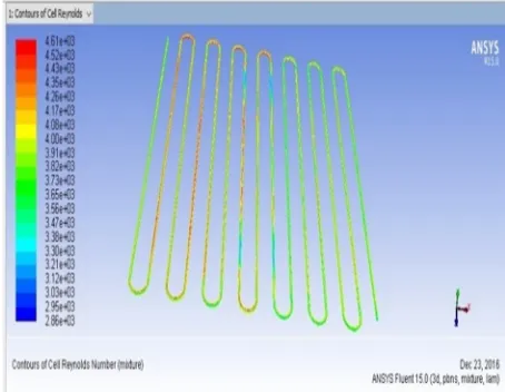
Figure: Contour of Reynolds number for (CuO + water) Nano fluid.
[image:9.612.203.411.496.655.2]From figure the value of Reynolds number is 59000 for 5.1 mm pipe diameter and for CuO + Water Nano fluid (i.e. Case 4). This is highest among all other Nano fluid.
Table 4: Reynolds numbers for different Nano fluid
Nano fluid Reynolds number
SiO2 + WATER CASE 1 27900
AL2O3 + WATER CASE 2 4250
Ti2O + WATER CASE 3 4610
CuO+ WATER CASE 4 59000
From table 4 we obtained the result, from the contour of Reynolds number for different Nano fluid and it was observed that the highest value for Reynolds number obtained with the CuO + Water Nano fluid i.e. Case 4 and hence we can say that the heat transfer will also increases with increasing Reynolds number of the flow.
Figure: Bar chart for comparing different Nano fluid with Reynolds number.
From figure the value of Reynolds number is 59000 gained for CuO + Water Nano fluid. This is peak among all other Nano fluid.
Now the value of Nusselt number and the value of heat transfer coefficient for CuO + Water Nano fluid i.e. Case 4 are to be obtained with the help of contour of Nusselt number and surface heat transfer coefficient which are as below.
0 10000 20000 30000 40000 50000 60000 70000
Reynolds number
Technology (IJRASET)
Figure: Contour of Surface Nusselt number for 5.1 mm pipe diameter & for (CuO + water) Nano fluid Case 4.
From figure the value of Nusselt number is 3570 for 5.1 mm pipe diameter and for CuO + Water Nano fluid. This is highest among all other Nano fluid.
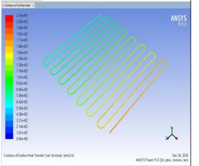
Figure: Contour of Surface heat transfer coefficient 5.1 mm pipe diameter & for (CuO + water) Nano fluid Case 4.
From figure the value of Surface heat transfer coefficient is 2140 w/m2-k for 5.1 mm pipe diameter and for CuO + Water Nano fluid Case 4. This is highest among all other Nano fluid.
V. CONCLUSION
This research presents overview about Nano fluid with solar collector applications, an existing emerging class of heat transfer fluid, in terms of barriers, future research and environmental challenges. Nano fluids are used to increase the performance of many thermal engineering systems.
By referring the experimental investigation [55], the main objective is to prepare a CFD model and using Nano fluid as flowing fluid, which investigate the efficiency of square flat plate solar collector and enhancement in heat transfer with the use of different Nano fluid as compare to water . Therefore we are adopting the simulation method to resolve the problem of Use of Nano fluid in the flat plate collector and to get the improved results by using computational fluid analysis in ANSYS 15.0 by FLUID FLOW FLUENT solver.
The center point was to evaluate the use of different Nano fluid in the developed region of the tube flow containing water + Nano fluid (Al203 and Ti2O, CuO, and SiO2) on heat transfer characteristics. It was perceived that all Nano fluids (Al203 and Ti2O, CuO,
and SiO2) revealed higher heat transfer characteristics than that of the base fluid (water). Furthermore the Nusselt number and the surface heat transfer coefficient is higher for CuO + Water Nano fluid as compare to other Nano fluid which are investigated on the basis of Reynolds and Nusselt number.
Technology (IJRASET)
[2] Wen D, Ding Y. Experimental investigation into convective heat transfer of nanofluids at the entrance region under laminar flow conditions. International Journal of Heat and Mass Transfer.2004a; 47: 5181-5188.
[3] Wen D, Ding Y. Effective thermal conductivity of aqueous suspensions of carbon nanotubes (CNT Nanofluids). Journal of Thermophysics and Heat Transfer.2004b; 18: 481-485.
[4] Lee S, Choi SUS, Li S, Eastman JA. Measuring thermal conductivity of fluids containing oxide nanoparticles. Transactions of the ASME, Journal of Heat Transfer.1999; 122: 280-289.
[5] Wang X, Xu X, Choi SUS. Thermal conductivity of nanoparticle fluid mixture. Journal of Thermophysics and Heat Transfer.1999; 13: 474-480.
[6] Keblinski P et.al. Mechanisms of heat flow in suspensions of nano-sized particles (Nanofluids). International Journal of Heat Mass Transfer.2002;45: 855-863. [7] Xuan Y, Li Q. Heat transfer enhancement of nanofluids. International Journal of Heat and Fluid Flow.2000; 21:58-64.
[8] Choi SUS, Zhang ZG, Yu W, Lockwood FE, Grulke EA. Anomalously thermal conductivity enhancement in nanotube suspensions. Applied Physics Letters. 2001; 79: 2252-2254.
[9] Eastman JA, Choi SUS, Li S, Yu W, Thompson LJ. Anomalously increased effective thermal conductivity of ethylene glycol based nanofluids containing copper nanoparticles. Applied Physics Letters.2001; 97:718-720.
[10] Luque A, Hegedus S. Handbook of photovoltaic science and engineering. England: Wiley; 2003.
[11] Chow TT. A review on photovoltaic /thermal hybrid solar technology. Applied Energy.2010; 87(2): 365-79. [12] Maxwell JC. Treatise on electricity and magnetism.Oxford: Clarendon Press US; 1973.
[13] Jaisankar S, Ananth J, Thulasi S, Jayasuthakar ST, Sheeba KN. A comprehensive review on solar water heaters. Renewable and Sustainable Energy Reviews.2011; 15-6: 3045-3050.
[14] Das SK, Putra N, Thiesen P, Roetzel W. Temperature dependence of thermal conductivity enhancement for nanofluids. ASME Journal of Heat Transfer.2003a; 125: 567-574. [17] Wen-xiao Chu, Ting Ma, Min Zeng, Ting Qu, Liang-bi Wang, Qiu-wang Wang, Improvements on maldistribution of a high temperature multi-channel compact heat exchanger by different inlet baffles, Energy, Volume 75, 1 October 2014, Pages 104-115
[15] Patel HS, Das SK, Sundarajan T, Nair AS, George B, Predeep T. Thermal conductivity of naked and monolayer protected metal nanoparticles based nanofluids: Manifestation of anomalous enhancement and chemical effects. Applied Physics Letters.2003; 83: 931-2933.
[16] Eastman JA, Phillpot, Choi SUS, Keblinski K. Thermal transport in nanofluids. Annu. Rev.Material. Res.2004; 34: 219-246.
[17] Omid Mahian, Ali Kianifar, Soteris, Kalogirou A, Loan Pop, Somchai Wongwises. A review of the applications of nanofluids in solar energy. International Journal of Heat Mass Transfer. 2013; 57: 582-594.
[18] Tyagi H, Phelan P, Prasher R. Predicted efficiency of a low-temperature nanofluid based direct absorption solar collector. Journal of Solar Energy Engg.2009; 131: 041004.
[19] Taylor RA, Phelan PE, Otanicar TP, Walker CA, Nguyen M, Trimble S, Prasher R. Applicability of nanofluids in high flux solar collectors. Journal of Renewable and Sustain Energy.2011; 3: 023104.
[20] Li Y, Xie H, Yu W, Li J. Investigation on heat transfer performances of nanofluids in solar collector. Material Science Forum.2011; 694: 33–36.
[21] Yousefi T, Veysi F, Shojaeizadeh E, Zinadini S. An experimental investigation on the effect of Al2O3-H2O nanofluid on the efficiency of flat-plate solar collectors. Renew Energy.2012; 39: 293-298.
[22] Yousefi T, Shojaeizadeh E, Veysi F, Zinadini S. An experimental investigation on the effect of pH variation of MWCNT-H2O nanofluid on the efficiency of flat-plate solar collectors. Solar Energy.2012; 86: 771-779.
[23] Khullar V, Tyagi H, Phelan PE, Otanicar TP, Singh H, Taylor RA. Solar energy harvesting using a nanofluids-based concentrating solar collector in: Proceedings of MNHMT2012 3rd Micro/Nanoscale Heat & Mass Transfer InternationalConference on March 3–6, Atlanta, USA, 2012.
[24] Titan C.Paul, Morshed AKM M, Jamil A.Khan. Nanoparticle enhanced ionic liquids (NEILS) as working fluid for the next generation solar collector. Procedia Engineering, 5th BSME International Conference on thermal engineering.2013; 56: 631-636.
[25] Otanicar TP, Phelan PE, Prasher RS, Rosengarten G, Taylor RA. Nanofluid based direct absorption solar collector. Journal of Renewable and Sustain. Energy.2010; 2: 033102.
[26] He Y, Wang S, Ma J, Tian F, Ren Y. Experimental study on the light-heat conversion characteristics of nanofluids. Nanosci.Nanotechnol Letters.2011; 3: 494– 496.
[27] Faizal M, Saidur R, Mekhilef S. Potential of size reduction of flat-plate solar collectors when applying MWCNT nanofluid. 4th International Conference on Energy and Environment (ICEE 2013), Conf.Series: Earth and Environmental Science.2013; 16:012004.
[28] Hong TK, Yang HS, Choi CJ. Study of the enhanced thermal conductivity of Fe nanofluids. Journal of Applied Physics.2005; 97: 064311.
[29] Eastman JA, Choi US, Li S, Thompson LJ, Lee S. Enhanced thermal conductivity through the development of nanofluids. Materials Research Society Symposium Proceedings. Materials Research Society, USA. 1997; 457: 3-11.
[30] Lee S, Choi US, Li S, Eastman JA. Measuring thermal conductivity of fluids containing oxide nanoparticles. Transactions of the ASME, Journal of Heat Transfer.1999; 121: 280-289.
[31] Masuda H, Ebata A, Teramae K, Hishinuma N. Alteration of thermal conductivity and viscosity of liquid by dispersing ultrafine particles (Dispersion of γ- Al2O3 , SiO2 and TiO2 ultra-fine particles). Netsu Bussei. 1993; 7: 227-233.
[32] Zhu H, Zhang C, Tang Y, Wang J, Ren B, Yin Y. Preparation and thermal conductivity of suspensions of graphite nanoparticles. Carbon.2007; 45: 226–228. [33] Xie H, Wang J, Xi T, Liu Y. Thermal conductivity of suspensions containing nano sized SiC particles. International Journal of Thermophysics.2002a; 23:
571-580.
[34] Xie H, Wang J, Xi T, Ali F. Thermal conductivity of suspensions containing nanosized alumina particles. International Journal of Thermophysics.2002b; 91: 4568-4572.
[35] Xie H, Wang J, Xi T, Liu Y, Ali F. Dependence of the thermal conductivity of nanoparticle-fluid mixture on the base fluid. Journal of Materials Science Letters.2002c; 21: 1469-71.
Technology (IJRASET)
[37] Jacopo Buongiorno, David C.Venerus et.al. A benchmark study of the thermal conductivity of nanofluids. Journal of Applied Physics.2009; 106: 094312. [38] Zhao Jia-Fe, Luo Zhong-Yang, Ni Ming-Jiang, Cen Ke-Fa. Dependence of nanofluid viscosity on particle size and pH value. Chinese Physics Letters.2009;
26(6): 256-307.
[39] Madhusree Kole, Dey TK. Viscosity of alumina nanoparticles dispersed in car engine coolant. Experimental Thermal and Fluid Science.2010; 34(6): 677-683. [40] Lee S, Choi SUS. Application of metallic nanoparticle suspensions in advanced cooling Systems. ASME Publications. 1996; 342/MD 72: 227-234.
[41] Xuan Y, Li Q. Investigation on convective heat transfer and flow features of nanofluids. Transactions of the ASME, Journal of Heat Transfer.2003; 125: 151- 155.
[42] Putra N, Roetzel W, Das SK. Natural convection of nano-fluids. Heat and Mass Transfer.2003; 39: 775-784.
[43] Yang Y, Zhang ZG, Grulke EA, Anderson WB, Wu G. Heat transfer properties of nanoparticle-in-fluid dispersions (nanofluids) in laminar flow. International Journal of Heat Mass Transfer.2005; 48: 1107-1116.
[44] Chun BH, Kang HU, Kim SH. Effect of alumina nanoparticles in the fluid on heat transfer in double-pipe heat exchanger system. Korean Journal of Chem. Eng.2008; 25(5): 966-971.
[45] Chandrasekar M, Suresh S, Chandra Bose A. Experimental studies on heat transfer and friction factor characteristics of Al2O3/water nanofluid in a circular pipe under laminar flow with wire coil inserts. Exp. Therm. Fluid Sci.2010; 24: 122-130.
[46] Suresh S, Venkitaraj KP, Selvakumar P. Comparative study on thermal performance of helical screw tape inserts in laminar flow using Al2O3/water and CuO/water nanofluids. Super lattices Microstruct.2011; 49: 608–622.
[47] Zamzamian A, Oskouie SN, Doosthoseini A, Joneidi A, Pazouki M. Experimental investigation of forced convective heat transfer coefficient in nanofluids of Al2O3/EG and CuO/EG in a double pipe and plate heat exchangers under turbulent flow. Exp.Therm Fluid Sci.2011; 35: 495-502.
[48] Corcione M, Cianfrini M, Quintino A. Heat transfer of nanofluids in turbulent pipe flow. International Journal of Therm. Sci.2012; 56: 58-69.
[49] He Y, Jin Y, Chen H, Ding Y, Cang D, Lu H. Heat transfer and flow behavior of aqueous suspensions of TiO2 nanoparticles (nanofluids) flowing upward through a vertical pipe. International Journal of Heat Mass Transfer.2007; 50: 2272-2281.
[50] Yu W, France DM, Smith DS, Singh D, Timofeeva EV, Routbort JL. Heat transfer to a silicon carbide/water nanofluid. International Journal of Heat Mass Transfer.2009; 52: 3606-3612.
[51] Anoop KB, Sundararajan T, Das SK. Effect of particle size on the convective heat transfer in nanofluid in the developing region. International Journal of Heat Mass Transfer.2009; 52: 2189-2195.
[52] Ding Y, Alias H, Wen D, Williams RA. Heat transfer of aqueous suspensions of carbon nanotubes (CNT nanofluids). International Journal of Heat Mass Transfer.2006; 49: 240-250.
[53] Heriz SZ, Etemad SG, Esfahan MN. Experimental investigation of oxide nanofluids laminar flow convective heat transfer. International Communication of Heat Mass Transfer.2006; 33: 529-535.
[54] Fotukian SM, Nasr Esfahany M. Experimental study of turbulent convective heat transfer and pressure drop of dilute CuO/water nanofluid inside a circular tube. International Communication of Heat Mass Transfer.2010a; 37: 214–219.
[55] Aminreza Noghrehabadi , Ebrhim Hajidavaloo , Mojtaba Moravej. Experimental investigation of efficiency of square flat-plate solar collector using SiO2/waternanofluid. Case Studies in Thermal Engineering 8 (2016) 378–386.
[56] M. Hasanuzzamana,b, R. Saidura,b and N.A. Rahimb “EFFECTIVENESS ENCHANCEMENT OF HEAT EXCHANGER BY USING NANOFLUIDS” 2011


![Table 2: Percentage Deviation in Efficiency of Present CFD analysis for Nano fluid (SiO2+ water) compare with Experimental data of Water by referring [55]](https://thumb-us.123doks.com/thumbv2/123dok_us/8576522.859555/7.612.34.580.425.608/percentage-deviation-efficiency-present-analysis-compare-experimental-referring.webp)