©IJRASET 2015: All Rights are Reserved
689
Hybrid Power Generation and Automatic
Railway Gate Control
M.Ramanathan1, S.Santhosh2, M.Prabu3, R.Yuvaraj4, C.Pazhanimuthu5 1234
Final Year Students, 5AP, Department of EEE, K.S.R. College of Engineering, Namakkal
Abstract- enerating electric power from the railway tracks and controlling the railway gates in automatic manner. Power consumption is increasing day by day due to modern civilization and industrialization. One of the key points to reduce the demands and dependency on the fossil fuels and the emission of the green house gases by the help of using green energy resources. Green energy sources such as solar, hydropower, biomass, geothermal and tidal power could meet the energy demand with reduced pollution on the environment and global warming. However they are not economical and the land used for the generation also high and low generated power density per unit area. Utilising the wind energy that available near by the railway tracks with the help of helical wind turbine. It has the potential to use the maximum wind when the locomotive is moving on the tracks and lower cost than the fossil fuels. The idea to generate the power is not new; it is practically used in high wind availability places. In this paper power generate by the wind that is developed by the movement of locomotive. Also generating the electric power from the vibration of the tracks when the locomotive passing on the track. A stepper motor is used to converts the vibration into electricity. The generated electricity is synchronised with the power from wind generator and stored in battery. Railway gate is controlled by the help of man power or the infra red sensor mounted on the track. The problem over that method is, if any object that crossing the sensor then the railway gate is closed. This cause unwanted traffic over the road. Mechanical damage of the cable is running from the sensor to the gate and the damage of sensors due to the atmospheric conditions such as lightning and dust. The problem is overcome in this paper with the help of Radio Frequency transmitter and receiver. Transmitter is fixed on the head of the locomotive and the receiver is located near by the railway gate. When the train comes in to the receiver range then the signal received by the receiver and the gate is closed. When the train leaves the gate then the gate is automatically opened.
I. INTRODUCTION
©IJRASET 2015: All Rights are Reserved
690
simulations to determine the optimum frequency at which to tune the device for a fixed value of mass and damping in the device[10].An efficient electromagnetic energy harvester featured with mechanical motion rectifier (MMR) is designed to recover energy from the vibration-like railroad track deflections induced by passing trains. Trackside electrical infrastructures for safety and monitoring typically require a power supply of 10-100 Watts, such as warning signals, switches, and health monitoring systems, while typical existing vibration energy harvester technologies can only harvest sub-watts or milliwatts power [11].Non resonant vibration to electrical power generation which can scavenge energy for wide frequency spectrum.the generator is capable of producing 11 milliwatts of power from vibration frequency of 60-140 Hz [12].Automatic railway gate control is implemented by the help of IR sensors mounted on the either side of railway track. Microcontroller receives the information from the IR sensors and produces the control signal to the gate. The atmega8 provides the standard 8K bytes of flash, 256 bytes of RAM, 32 I/O lines, three 16-bit timer/counters, a six-vector two-level interrupt architecture, a full duplex serial port, on-chip oscillator, and Clock circuitry. Geared stepper motor is used to drive the gate [13]. Unmanned level crossing where the chances of accidents are higher and reliable operation is required. Since, the operation is automatic and error due to manual operation is prevented. The system works on a microcontroller based control. The proposed system uses AT mega 16A microcontroller. With the help of IR sensors .The arrival and leaving of the system is monitored and the gate is operated accordingly. Servo motor with gear box is used to drive the gate in the level crossing [14].
This work is concentrated on predicting the major cause of railway accidents that is collision on the same track. The primary goal of this anti-collision system is to identify collision points and to report these error cases to main control room, nearby station as well as grid control stations. Implementation of an efficient Zig-Bee based train anti-collision for railways is used in the system [15]. The obstacle sensor is used to sense the obstacle and microcontroller is used to take the decision and to transmission and reception of the signals. This system is designed to use in all the level crossing and the whole network. Vibration sensors are also used in the tracks to sense the vibrations and send it to the microcontroller [16]. The train is having two transmitters to send the packet of data. The receiver is mounted far from the gate and receives the information and sends to the CPU. Gate control is done by CPU by providing control signals [17]. RF based sender and receiver kits to provide the necessary functions to the train locomotives. And when two trains are near automatically the electrical braking system is applied on both the trains and stops the train [18]. The proposed system includes several features which prevent train accidents. It includes automatic speed controlling in curves, collision detection, fire detection, detaching of couch automatically when fire is detected in it, automatic railway gate control and track continuity. This system makes use of IR sensors, fire sensor, Zig-Bee and other embedded systems [19]. This paper has proposed the implementation of a global positioning system (GPS) based train monitoring system that could locate a train at every instant. Here a GPS–GPRS module transmits the location information to a web server [20].
II. POWER GENERATION USING WIND ENERGY AND VIBRATION ENERGY
A. Power Generation Using Wind Energy
The electricity produced in the world by the conventional energy sources are 79% in 2011.the fossil fuels are reducing day by day and also causes global warming and other problems on the environment. So we need to produce the electricity from the clean and renewable energy.non conventional energy sources such as solar, wind, geothermal and hydro energy are used. Over the years, wind energy developments have led to increased turbine size and capacity, while greatly reducing the cost. The wind energy market is rapidly expanding worldwide. The global installed wind capacity is increased from 1.7 GW (1700 MW) in 1990 to 100 GW in 2008, over 27 GW of which came online in 2008 alone. From 1997, it increased at a rate of 35% per year, and the market has grown at a rate of 29%. In 2008, six countries, namely United States, China, India, Germany, Spain and Italy added capacities of more than 1 GW. In 2009, the installed wind power capacity in the EU reached 74.7 GW (up from 64.7 GW at the end of the previous year).
1) Energy availability in the wind: The power that is available in the wind depends on the wind speed, the density of the wind (which varies with altitude and temperature), and the amount of turbulence (swirling) in the wind. Wind speed is high up in the sky and low at the ground level.
The power available at a given wind speed passing through an area can be calculated by using the following formula: P= ½. Av3
Where,
P - Power in watt (W)
691
A - The cross section area of the wind passing through in square .meter (m) v - The velocity of the wind in meter per second (m/s)
B. Electric Power Generation Using Vibration Energy
An efficient electromagnetic energy harvester featured with mechanical motion rectifier (MMR) is designed to recover energy from the vibration-like railroad track deflections induced by passing trains. Trackside electrical infrastructures for safety and monitoring typically require a power supply of 10-100 Watts, such as warning signals, switches, and health monitoring systems, while typical existing vibration energy harvester technologies can only harvest sub-watts or milliwatts power. The proposed harvester is designed to power major track-side accessories and possibly make railroad independent from national grid. To achieve such a goal we implement the MMR, a patented motion conversion mechanism which transforms pulse-like bidirectional linear vibration into unidirectional rotational motion at a high efficiency. The single-shaft MMR design further improved our previously developed motion mechanism, increased energy harvester efficiency and expanded power harvesting potential. The proposed new design improved reliability, efficiency, and provided steadier power output. Bench test of the harvester prototype illustrated the advantages of the MMR based harvester, including up to 71% mechanical efficiency and large power output.
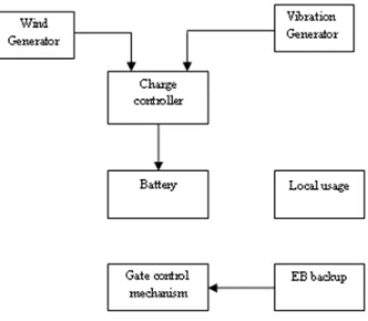
[image:4.612.202.403.271.466.2]III. PROPOSED HYBRID POWER GENERATION
Fig. 3.1 Proposed model of hybrid power generation
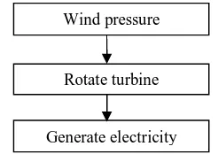
A. Wind Energy Conversion (WEC)
Figure 3.2 processes involved in WEC
Wind energy converters capture the air flow by converting it into a rotational movement, which subsequently drives a conventional generator for electricity.There are two primary principles by which energy can be extracted from the wind. They are through creation of either drag or lift force (or through a combination of the two).
1) The lift force is perpendicular to the wind direction. It is caused by a pressure difference between the airs on either side of the blade.
2) The drag source in the same direction as the wind. It is the force felt by a person exposed to the wind.
The ratio between lift and drag largely depends on the shape of the blade and the angle of the main line of the blade (chord line) and the main wind direction – the angle of attack. Depends on the design of the turbine, either drag or lift moves the blades.
Wind pressure
Rotate turbine
[image:4.612.245.368.507.594.2]692
Most wind turbine today use the principle of lift rather than drag. The basic features that characterize lift and drag are:
1) Drag is in the direction of air flow
2) Lift is perpendicular to the direction of air flow
3) Generation of lift always causes a certain amount of drag to be developed
4) With a good aerofoil, the lift produced can more than thirty times greater than the drag
5) Lift devices are generally more efficient than drag devices.
(i)
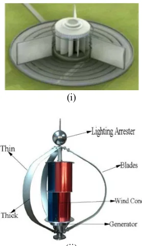
[image:5.612.236.375.153.393.2](ii)
Fig. 3.3 Typical vertical axis wind turbine model
B. Power Generation with Helical Wind Turbines
In this paper the wind turbine is located near by the railway track. The vertical axis wind turbine is preferred for the generation. It because of several problems associated with the horizontal axis wind turbine when it is used in railway track. In horizontal axis wind turbine, the blade length is high so it need larger place for installing in railway track. Since it located far from track so it collects less amount of wind and produce less electric power. Vertical axis blades are made by aluminium or fibber material. The blade materials are less weight and more mechanical strength. The metal or fibber sheet is cut and designed as a helical blade. The blade thickness is depends upon the wind speed availability in the railway track and speed of the locomotive.
C. Gears and Generators
Usually the wind turbine rotates slowly and not enough to produce the voltage on the generator. So we need to increase the speed of generator. It is done by the help of the gear arrangement. The turbine shaft is connected to the gear and then the gear shaft is connected to the generator. The gear arrangement increases the speed of generator. One rotation of turbine is converted into multiple rotations by the gear. Number of rotation is depends upon the number of teeth’s in the gear.
D. Energy Available In Railway Track
693
Fig. 3.4Vertical deflection of the railroad track
The normal load exerted by the freight train wheels on the track is 20 to 30 tons. The loaded train is having the maximum weight of 140 tons. Average track displacements range from 7mm to 12mm.Track displacements go as high as 25mm, which has been recorded for regions servicing trains of over 100 tons of weight. Usually freight trains have different cart lengths so the distance between bogies is not uniform.
For a train moving at 40 mph, track vibration frequencies can fall between 1.6 Hz to 4Hz, depending on the distance between bogies and the distance separating wheel pairs of a bogie. The peak speed of track deflection mainly depends on the velocity of the train. Peak track speeds can be of values of 10 cm/s or higher for trains moving at an average velocity of 40mph. Track deflections are often even larger at grade crossings due to sudden changes in track structure and stiffness at these instalments. The normal force used is between 89 to 133 kN, the total distance moved by the track is estimated to be between 20 mm and 28 mm. For a train with160m length between bogies moving at a speed of 40km/hr, an average available power of 3kw to 5kw can be harvested from railroad track deflections. Considering the goal to power equipment with up to 100 Watts rating, we only use less than 3% of the available power of the track.
E. Vibration Generator
As per the faradays law of electromagnetic induction, whenever the current carrying conductor revolving at the magnetic field the EMF induced on the conductor. Generated EMF is directly proportional to the speed of the conductor rotating at the magnetic field. Normally induced EMF in the generator is alternating current.
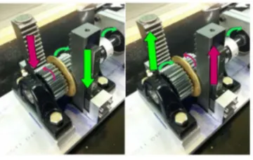
Fig. 3.5 Principle of vibration generation
In DC shunt generator the field winding of motor is connected in series with the armature. Commutator is used to convert the induced AC EMF into DC EMF. The Voltage is collected from the commutator by the help of carbon brushes mounted on the generator. From the fixe terminal the voltage is taken out from the generator.
[image:6.612.217.397.467.581.2]©IJRASET 2015: All Rights are Reserved
694
F. Principle Of Proposed System
The racks transmit vertical up and down motion to the two pinions. The rack pinion assembly causes the two pinion gears to rotate in opposite directions with respect to one another. The pinions are fitted with unidirectional roller clutches. The roller clutches, engage the shaft only when rotating in a specific direction of rotation. In either direction of rack motion, one of the pinions will engage the input shaft and the other pinion will disengage it. By installing both roller clutches to engage the input shaft in the same direction, the shaft moves in a unidirectional motion.
The unidirectional rotational input motion is then fed to a generator gear head, which amplifies the low speed input of the pinion shaft to optimal generator speed values. The electric generator thus spins in unidirectional motion at its efficient operating speeds. Electrical power will be produced from the electric generator as it spins. It is important to note that the input shaft may also coast, or spin freely. In this case, both pinions disengage. This is a crucial feature for flywheel implementation. The generator contains an output shaft in which a flywheel is installed. This flywheel stores kinetic energy through spinning. The flywheel is designed to lend its kinetic energy to the generator when there is no input motion from the track. Moments in which there is no input motion to the gear racks occur in between bogies. During these moments, the generator is powered by the flywheel, allowing for generation of consistent continuous voltage output.
G. Electric Power Storage
Electric output from the wind generator is given the charge controller and the output from the vibration generator is also given to the controller. Now the controller controls the voltage as 12 V constant even the voltages gets increased. Now the two powers are synchronised in the controller. The synchronised power is stored in battery and it used for the gate control mechanism and for the local usage.
H. EB Backup
Figure 6.5 shows the EB backup unit and its various parts are discussed below
Fig3.6 EB backup
1) Rectifier: Bridge rectifier circuit is used in this system. It is now available in a single entity. It is IR BR 6840.here IR stands for INTERNATIONAL RECTIFIER that is company manufacturing the product. BR stands for Bridge Rectifier.6 stands for its ratting that is 600V.Rectifier is used for converting AC into pulsating DC.Here instead of using DC source such as battery we are using the rectifier because those source have less life time.
2) Filter: Filtering should be done in order to reduce the harmonics and ripples. for these purpose we used capacitors for the filtering. They are rated at 100W.here output voltage from rectifier is 100V.the capacitors are used in two arms. they share this voltage equally. The capacitors are rated at 100µF/100v.each of the capacitors shares 50V.the capacitors are electrolytic in nature.
3) Regulator: Regulator IC unit contains the circuitry for reference source, comparator amplifier, control device and overload production in a single IC. Although internal construction of the IC somewhat different from that described one, the external operation is the same. IC units provide regulation of a fixed positive voltage, fixed negative voltage or an adjustable set voltage. A power supply can be built using transformer connected to the AC supply line to step the AC voltage to the desired amplitude. After that it is rectified filtered with a capacitor and finally regulating the DC voltage using on IC regulator. The regulators can be selected for operation with load current from hundreds of milli amperes to tones of amperes, corresponding to the power rating from milli watts to tens of watts
IV. GATE CONTROL MECHANISM
There are many railway crossings which are unmanned due to lack of manpower, needed to fulfil the demands. Hence, much accident security such crossings, the functioning of the railway gate when a train approaches the crossing. Now a days, India is the country which having world’s largest railway network. Over hundreds of railways running on track every day .As we know that it is surely impossible to stop, the running train at instant is some critical situation or emergency arises. Train accidents having serious repercussion interms of loss of human life, injury, damage to Railway property. These consequential train accidents-include Collision, Derailments, Fire in Trains, and Collisions of train. Our country is a progressivecountry. It has already enough economical problems, which are ever been unsolved.
Power supply
Rectifi er
Filter Regula
695
A. Embedded System
Embedded systems are controllers with on chip control which consist of microcontrollers, input and output devices, memories etc. and it can be used for a specific application. A small computer designed in a single chip is called single chip microcomputer. A single chip microcomputer typically includes a microprocessor, RAM, ROM, timer, interrupt and peripheral controller in a single chip. This single chip microcomputer is also called as a microcontroller. These microcontrollers are used for variety of applications where it replaced the computer. The usage of this microcomputer for specific applications, in which the microcontroller a part of application is called, embedded systems. Computing systems are everywhere. It’s probably no surprise that millions of computing systems are built every year destined for desktop computers (Personal Computers, or PC’s), workstations, mainframes and servers. Thus an embedded system is nearly any computing system other than a desktop, laptop, or mainframe computer.
[image:8.612.225.391.563.708.2]1) Transmitter: In general, the function of a radio frequency (RF) transmitter is to modulate, up convert, and amplify signals for transmission into free space. An RF transmitter generally includes a modulator that modulates an input signal and a radio frequency power amplifier that is coupled to the modulator to amplify the modulated input signal. The radio frequency power amplifier is coupled to an antenna that transmits the amplified modulated input signal. Power amplifiers are required in radio telecommunication systems to amplify signals before transmitting, because a radio signal attenuates on the radio path. For efficiency, the amplifier is often a non-linear amplifier operated near its peak capacity. To avoid distortion of the transmitted signals due to the non-linearity, the signals are pre-distorted by a pre distorter before they are transmitted.
Fig. 4.1RF Transmitter
The pre distortion is required to prevent transmitter from transmitting signals on channel bands other than the band assigned to the transmitter. Digital pre distortion may be performed by multiplying the modulated signals prepared for transmission by a set of pre distortion values. The pre distortion values are chosen such that the product values entering the power amplifier will be distorted by the power amplifier to return to a substantially linear amplification of the modulated signals.RF transmitters are usually subject to Regulatory requirements which dictate the maximum available transmitter power output harmonics and the bandage and requirements.
2) Receiver: Radio frequency (RF) is a rate of oscillation in the range of about 3khzto 300 GHz, which corresponds to the frequency of radio waves, and the alternating currents which carry radio signals. RF usually refers to electrical rather than mechanical oscillations, although mechanical RF systems do exist when you turn the emitter switch on, the lamp of the receiver begins to glow. When you turn the switch of the emitter off, the lamp of the receiver darkens. And so on. If the receiver has been build a basic way, then the distance over which the communication works will be a few meters or a few tens of meters:
Fig. 4.2 Block diagram of gate control
RF Transmitter
696
4.3 RF receiver
When the frequency of the transmitter is increased, then we can increase the distance of the transmission. 300MHZ of RF can transmit the signal up to 30 KM distance. Here we need to transmit the signal up to 10KM.so 100MHZ of RF is enough to transmit the signals. During transmission 20 db of signal get losses in the medium. An RF receiver module receives the modulated RF signal, and demodulates it.
3) AT mega 8 controller: AT mega8 controllers is used to control the railway gate in automatic manner. Out of three ports PORT B is used for the operation. In PORT B 4 I/O pins are used.1 pin is used for receive the input signal from the RF receiver. Other 3 pins are used for the controlling of gate operation.
When the train arrives in the receiver range the controller receives the signal. When the signal is received the controller processes the information and produces the output signals on the other pins. Second pin is used to alert the people the gate is going to close now. After some time delay the third pin produce the output and supply the gate motor and close the railway gate. After closing the gate the motor is automatically turned off.
When train leaves the receiver range the signal to the controller is automatically turned off. Now the controller produces the control signal in fourth pin to reverse the supply to the motor. Now the motor rotates in reverse direction and opens the gate. After opening the gate the limit switches are used to turn off the motor after certain level.
V. CONCLUSION
The economics and the benefits of renewable sources of energy and in particular wind power are becoming increasingly convincing across the globe. Wind has the advantages of stable generation costs, low operating costs, renewable, short energy payback, less time-to-market, abundant resource, and environmentally preferable. A single-shaft MMR based energy harvesting prototype has been developed and demonstrated much better performances than existing technologies in the field of railway energy harvesting. The up and down oscillating vibration is converted into a unidirectional rotation of the generator. The above are hydrideand used to control the railway gate. RF based railway gate control is very reliable and most cost effective method.
REFERENCES
[1] Indu R. Pillai, Rangan Banerjee, “Renewable energy in India: Status and potential”, Department of Energy Science and Engineering, Indian Institute of Technology Bombay, Powai, Mumbai 400076, India
[2] L. Battisti, G. Soraperra, R. Fedrizzi and L. Zanne, “In- verse Design-Momentum, a Method for the Preliminary Design of Horizontal Axis Wind Turbines”. Journal of Physics: Conference Series, Vol. 75, 2007, Article ID: 012013.
[3] H. Dumitrescu, A. Dumitrache, C. L. Popescu, M. O. Popescu, F. Frunzulică and A. Crăciunescu”GheorgheMihoc, “Wind Tunnel Experiments on Vertical-Axis Wind Turbines with Straight Blades”, International Conference on Renewable Energies and Power Quality (ICREPQ’14) Cordoba (Spain), 8th to 10th April, 2014 Renewable Energy and Power Quality Journal (RE&PQJ) ISSN 2172-038 X, No.12, April 2014
[4] Direct Driven Generators for Vertical Axis Wind Turbines. ActaUniversitatis, Upsaliensis. Digital comprehensive summarise Uppsala Dissertations from the faculty of science and technology 547.88pp. Uppsala.ISBN 978-91-554-7264-1
[5] Michaela D. PlatzerU.S., “Wind Turbine Manufacturing Federal Support for an Emerging Industry Specialist in Industrial Organization and Business”, December 18, 2012.
[6] HazemElzarka, Ph.D., PE, and Taylor Andrews, University of Cincinnati, “Feasibility of Wind Turbine Systems in Highway Maintenance Facilities” [7] Vijay Devabhaktuni, MansoorAlam, PremchandBoyapati, PankajChandna, Ashok Kumar,Lewis Lack, Douglas Nims, and Lingfeng Wang, “Wind
Energy: Trends and Enabling Technologies”.
[8] NeerajPareta,NaveenSen, “Modelling and Simulation of Permanent Magnet Synchronous Motoer Based Wind Energy Conversion System”, International Journal of Emerging Research in Management &Technology ISSN: 2278-9359 (Volume-3, Issue-7)
[9] Sushant N. Malave, “Highway Wind Turbine”, International Journal of Mechanical Engineering and Research,ISSN No. 2249-0019, Volume 3, Number 5 (2013), pp. 529-534.
©IJRASET 2015: All Rights are Reserved
697
Vibration Problems.Lisbon, Portugal, 9-12 September 2013.[11] Teng Lin, John Wang, and Lei Zuo, “Energy Harvesting from Rail Track for Transportation Safety and Monitoring”.
[12] Dirk spreemann,B.Folkmer,D.Mintenbeck,Y.manoli, “ Novel non resonant vibration transducer for energy harvesting” ,Fifth international workshop on micro and nano technology for power generation and energy conversion applications, university of Tokyo, Japan.
[13] M. M. Islam, A. Halder and F. Ahmed, “Enhancing security by Automatic Railway Gate Control using Microcontroller and IR Sensor”, Proceedings of 10th Global Engineering, Science and Technology Conference 2-3 January, 2015, BIAM Foundation, Dhaka, Bangladesh, ISBN: 978-1-922069-69-6 [14] Acy M. Kottalil ,Abhijith , Ajmal M , Abhilash L J ,AjithBabu, “Automatic Railway Gate Control System”,International Journal of Advanced Research
in Electrical, Electronics and Instrumentation Engineering Vol. 3, Issue 2, February 2014
[15] Mr. N. Sambamurthy, Sk. HasaneAhammad, Mr. N. Sambamurthy et al, “Prevention of Train Accidents Using Wireless Sensor Networks”, Int. Journal of Engineering Research and Applications www.ijera.com ISSN: 2248-9622, Vol. 3, Issue 6, Nov-Dec 2013, pp.1592-1597
[16] N.Ramasamy, “Automatic Obstacle Detection in Railway Network Using Embedded System”, International Journal of Industrial Electronics andElectrical Engineering, ISSN: 2347-6982 Volume-2, Issue-6, June-2014
[17] Sheikh ShanawazMostafa , Md. MahbubHossian , KhondkerJahid Reza , GaziManiur Rashid , “ A Radio Based Intelligent Railway Grade Crossing System to Avoid Collision”, JCSI International Journal of Computer Science Issues, Vol. 7, Issue 6, November 2010, ISSN (Online): 1694-0814 [18] Rohit Sharma, Pankaj Singh, PankajAgarwal, HimanshuTiyagi, “Automatic Braking System for Trains using Radio Frequency”, International Journal
of Soft Computing and Engineering (IJSCE) ISSN: 2231-2307, Volume-2, Issue-3, July 2012
[19] M.D.Anil1, Sangeetha.S, Divya.B ,Niranjana.B, Shruthi.K.S, “Advanced Railway Accident Prevention System Using Sensor Networks” , International Journal of Advanced Research in Computer and Communication Engineering, Vol. 3, Issue 5, May 2014.