Circular Microstrip Patch Antenna for RFID
Application
Swapnali D. Hingmire1, Mandar P. Joshi2, D. D. Ahire3
1,2,3 E&TC Department, 1R. H. Sapat COE, Nashik, 2,3Matoshri COE, Nashik,Savitri Bai Phule Pune University
Abstract: In this paper, circular microstrip patch antenna (CMPA), with coaxial probe feeding, have been proposed. The proposed antenna operates in the frequency range of (2.4-2.48) GHz RFID band. The antenna is fabricated on FR4 substrate with size of 50mm × 50mm × 1.6mm. The antenna is simulated using the method of moment's CAD FEKO antenna simulator. The measured and simulated results are found to be in good agreement.
Keywords— microstrip, circular, RFID, polarization, frequency
I. INTRODUCTION
Radio frequency identification (RFID) systems in UHF band have attracted many researcher’s attention for their popular applications in manufacturing companies and service industries. Radio frequency identification (RFID) technology allow users to uniquely identify tagged people or objects [13]. RFID employs electromagnetic (EM) waves to exchange information between readers and tags for the purpose of identification and tracking [11]. Microstrip antennas are used in many application because of its low profile, ease of fabrication and low cost. Circular patch or disk is the one of the popular configuration to design a Microstrip patch antenna [12].
S.J. Pawar et.al. proposed coaxial feed dual band circular microstrip patch antenna (CMPA) for ISM (2.4-2.5GHz) and WLAN
(5.150-5.350GHz) application. Dual frequency bands has been achieved by inserting a circular slot in the circular radiator as well as
bandwidth enhancement is achieved by modifying the ground plane[1]. D.D. Ahire et.al. proposed dual band rectangular microstrip
patch antenna using T-slot and capacitive loading. The ‘T’ shaped slot is used on radiator and ground plane to enhance the
bandwidth [2]. Xiong Ying Liu et.al. proposed a broadband circularly polarized stacked coin-shaped patch antenna for a universal
UHF-RFID reader. For achieving circular polarization, the main patch is fed by four probes, connected to the feeding strip with an
interval of a quarter-wavelength at 900 MHz [3]. Yu-Shao et.al.proposed a printed slot antenna that utilizes a ring slot and a cross
slot. Ring slot and cross slot controls the lower band and upper band respectively [4]. Lee Chang et.al, proposed a single-feed active
RFID tag antenna that operates in the microwave frequency. The reported antenna functions as a dipole when used in free space and it functions as a patch when applied on a metallic surface. The antenna structure contains no ground plane [5].
In this paper, circular microstrip patch antenna with coaxial feeding technique is presented for RFID application. This paper has been organized as in four main sections. Section I includes introduction, Section II depicts design of antenna for RFID application. Section III and IV shows analysis and results respectively.
II. ANTNNA DESIGN
The antenna geometry consists of circular patch with square cut inside the patch area to achieve circular polarization. The coaxial
probe feed is applied having location x = 4 and y = - 4 to the circular patch radiator. The circular patch radius (α) and ground plane
area of the antenna are 14.5 mm and 50mm × 50mm, respectively. The proposed antenna is designed on a FR4 substrate with
thickness, h = 1.6mm, dielectric constant, εr = 4.4. The diagonal corner of circular patch has been cut with dimensions of 6 mm × 8mm. The antenna resonates at 2.46 GHz for RFID (2.4-2.48) GHz band.
The geometry of circular microstrip patch antenna is depicted in fig.1.
The circular patch radius (α) is given in the following equation,
α (1)
Where,
α = Radius of circular patch
h = Height of substrate
εr = Relative permittivity of dielectric substrate
Fig.1: Geometry of proposed CMPA
III. PARAMETRIC ANALYSIS
Performance of circular microstrip patch antenna is dependent on different parameters such as radius of patch, size and location of rectangular slots, shape and size of ground plane. For designing a circular microstrip patch antenna for (2.4 - 2.48) GHz, it is
required to maintain the position of rectangular slots.They are rotated in 30˚ from vertical axis. Size of rectangular slots is selected
as 6mm × 8mm. For rectangular slot of size 5 mm × 7 mm the resonant frequency shifts towards lower band while for slot size of 7 mm × 9 mm resonant frequency shifts towards upper frequency band. Hence optimized slot dimension in order to satisfy the (2.4 - 2.48) GHz band is 6mm × 8mm.
The feed location is optimized and hence location selected is in between center and edge of the circular patch. The selected location of feeding for proposed antenna is, at x = 4 mm and y = - 4 mm, as depicted in the fig.1.
IV. RESULTS
The modeling and simulation of the proposed CMPA is performed using CADFEKO simulation software. The antenna is fabricated
with printed circuit board technology as shown in fig.2. A 50-Ω type-subminiature-A (SMA) connector is soldered at the feed point.
Fig.2: Fabricated CMPA
A. Simulated Results
From simulation, reflection coefficient for proposed circular microstrip patch antenna is depicted in fig.3. Simulated results presented above shows that proposed antenna resonates at 2.46 GHz with reflection coefficient of -18.27 dB with bandwidth of 60 MHz. Axial ratio for proposed circular microstrip patch antenna is depicted in fig.4. The figure shows that axial ratio for propsed
Ground
patch
Slots Radiating patch
SMA connector
Feed Point 14.5mm
CMPA is below 3 dB, which results in circularly polarized antenna.
Maximum current is observed at 2.46 GHz on the circular radiating patch. Current distribution is depicted in fig.5.
Fig.3: Reflection coefficient for proposed CMPA Fig.4: Axial ratio for proposed CMPA
(a) surface current at θ=0˚ and θ=90˚ respectively (b) surface current at θ=180˚ and θ=270˚ respectively
Fig.5(a)&(b) : Current Distribution at 2.46 GHz
Figures 5(a) and (b) presents that, arrow heads of current rotates clockwise. Hence right hand circular polarization (RHCP) has been acquired.
Radiation pattern for 2.46 GHz resonating frequency is depicted in fig.6. From simulated radiation pattern, maximum gain is 1.61 dBi at 2.46 GHz.
Fig.6: Radiation pattern at 2.46 GHz
B. Measured Results
with return loss of -22.55dB. This shows that a good impedance matching is achieved by proposed CMPA.
Fig.7: Measured Return Loss of CMPA
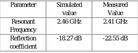
TABLE I: Simulated ans measured values for CMPA
Parameter Simulated
value
Measured Value Resonant
Frequency
2.46 GHz 2.41 GHz
Reflection coefficient
-18.27 dB -22.55 dB
V. CONCLUSIONS
The design and simulation of the proposed CMPA is carried out in this work. The measured and simulated results show that the proposed CMPA is a good candidate for, (2.4-2.48 GHz) RFID applications.
VI.ACKNOWLEDGMENT
Authors would like to thank Principal and H.O.D. E&TC of AVCOE, Sangamner, for providing measurement facilities.
REFERENCES
[1] Sayali J. Pawar and Mandar P. Joshi, “Design Of Dual Band Circular Microstrip Patch Antenna for ISM and WLAN,” 2016 International Conference on Automatic Control and Dynamic Optimization Techniques (ICACDOT), Pune, pp. (608-611), 2016.
[2] D.D. Ahire and G.K. Kharate, “Dual Band Microstrip Patch Antenna for Wireless Applications,” International Journal of Computer Technology and Applications (IJCTA), 9(10), pp. (1-11), 2016.
[3] Xiong Ying Liu, Yi Liu and M. M. Tentzeris, “A Novel Circularly Polarized Antenna with Coin-Shaped Patches And Ring-Shaped Strip For Worldwide UHF RFID Applications,” IEEE Antennas and Wireless Propagation Letters, Vol.14, pp.(707-710), 2015.
[4] Yu Shao and Zhangyou Chen, “A design of Dual-Frequency Dual-sence Circularly polarized Slot Antenna,” IEEE Transaction on ANtennas and propagation, Vol. 60, No.11, pp. (4992-4997), Nov. 2012.
[5] Le Chang, H. Wang, Z. Zhanh, Yue Li and Z. Feng, “Compact Single-Fed Dual-mode Antenna for Active RFID Tag Application,” IEEE Transactions on Antennas and Propagation, Vol.60, No.11, pp.(4992-4997), Nov. 2012.
[6] AkankshaFarswan, A. K. Gautam, B. K. Kanaujia and K. Rambabu, “Design of Koch Fractal Circularly Polarized Antenna for Handheld UHFReader Applications,” IEEE Transactions on Antennas and Propagation, Vol.64, No.2, pp.(771-775), Feb 2016.
[7] Chow-Yen-Desmond Sim, Yi-Wen Hsu and Gunali Yang, “Slits Loaded Circularly Polarized Universal UHF-RFID Reader Antenna,”IEEE Antennas and Propagation Letters, Vol.14, pp.(827-830), 2015.
[8] Rong Cao and Shun C. Yu, “Wideband Compact CPW-Fed Circularly Polarized Antenna for universal UHF-RFID Reader,” IEEE Transactions on Antennas and Propagation, Vol.63, No.9, pp.(4148-4151), Sept. 2015.
[image:5.612.195.417.325.410.2]Antennas and Propagation, Vol.61, N0.10, pp.(5283-5286), Oct 2013.
[11] Yi-Fang Lin, C. Lee, S. C. Pan and H. M. Chen,“Proximity-Fed Circularly Polarized Slotted Patch Antenna for RFID Handheld Reader,”IEEE Transactions on Antennas and Propagation, Vol.61, N0.10, pp.(5283-5286), Oct 2013.
[12] Zhi-Ning Chen, X. Qing and H. L. Chung, “A Universal UHF RFID Reader Antenna,” IEEE Transactions on Antennas and Propagation, Vol.57, No.5, pp.(1275-1282), May 2009.
[13] R. Want, “An introduction to RFID technology,” IEEE Pervasive Comput., vol. 5, no. 1, pp. 25−33, Jan. 2006.
[14] C. A. Balanis, Antenna Theory: Analysis and Design, 3rd ed. New York, NY, USA: Wiley, 2005.
[15] V. Hunt, A. Puglia, M. Puglia, RFID: A Guide to Radio Frequency Identification, New York, NY, USA: Wiley, 2007.