Analysis and Design of G+3 Residential Building using STRUDS
Uday Kumar
1, Aman Kumar Sharma
2, Anmol Kumar
3, Ayushkar Dubey
4, Geetha L
51,2,3,4
UG Students, Department of Construction Technology Management & Highway Technology, Dayananda Sagar
College of Engineering, Bengaluru, Karnataka, India
5
Assistant Professor, Department of Construction Technology Management & Highway Technology, Dayananda
Sagar College of Engineering, Bengaluru, Karnataka, India
---***---
Abstract -
The process of structural planning anddesign requires not only imagination and conceptual thinking but also sound knowledge of science of structural engineering besides the knowledge of practical aspects, such as recent design codes, bye laws, backed up by ample experience, intuition and judgment. It is emphasized that any structure to be constructed must satisfy the need efficiently for which it is intended and shall be durable for its desired life span.
STRUDS software is used to analyze and design the G+3 residential building. The purpose of using the software is that it is user friendly and has unique features like it designs the structural components individually along with their analysis and results. Another useful feature of this software is that Shear force, Bending moment, Torsion diagrams at each level of the building can be viewed. The AutoCAD plan along with its specification from the construction site is selected. After studying the plan and its criteria designing the structural components of building namely slabs, beams, columns and footings are carried out. This is followed by manual design and comparisons of results obtained through software.
Key Words: STRUDS1, Analysis2, Design3, Slabs4,
Beams5, Columns6, Footings7.
1. INTRODUCTION
The design process of structural planning and design requires not only imagination and conceptual thinking but also sound knowledge of science of structural engineering besides the knowledge of practical aspects, such as recent design codes, bye laws, backed up by ample experience, intuition and judgment. The purpose of standards is to ensure and enhance the safety, keeping careful balance between economy and safety. The process of design commences with planning of the structure, primarily to meet its functional requirements. It is emphasized that any structure to be constructed must satisfy the need efficiently for which it is intended and shall be durable for its desired life span.
Need for the design is to plan a structure, which meets the basic requirements of structural design are as follows:
Serviceability Safety Strength Durability
Economy
Aesthetic appearance
Feasibility, practicability and acceptability
All the component members are to be arranged so that they transmit their self-weight and other superimposed loads to foundation or supporting structure by cheapest means to satisfy the requirements of architecture and structural stability.
2. STRUDS
It is abbreviated for “STRUCTURAL ANALYSIS DESIGN AND DETAILING SOFTWARE’’. This software performs structural analysis for vertical as well as horizontal [seismic/wind] loads for RC framed structures and performs design as per IS norms.
Following are the salient features of STRUDS. Design of multi-storey and high rise reinforced
concrete buildings quickly and easily.
Design all building components including slabs, beams, columns, shear walls and foundations Apply a variety of loads like UDL, point loads and
external moments to the model
Design steel trusses supported by concrete columns Perform seismic analysis as per IS:1893
Generate detailed CAD drawings, design schedules, BOQ and calculation reports
Import and export building models with other structural software
Perform advanced 3D space frame analysis, with optional plane grid and plane frame analysis Perform wind load analysis to code IS:875
Apply seismic analysis by response spectrum analysis Consider floor diaphragm effect in analysis
Perform torsion analysis due to eccentricity between center of mass and center of rigidity
Undertake shear wall analysis
Produce analysis results for forces and displacements Produce clear diagrams for shear force, bending
moment and deflections
Product written and graphical representation for end moments and end reactions
Prepare floor-wise design schedules for all components Adopt ductile detailing as per IS:13920 and
normal detailing as per SP-34
Generate multi-layered DXF drawings for slabs, beams, columns, shear walls and footings
Produce BOQ / material lists of concrete and steel components including slabs, beams, columns, foundations.
Export models to other structural software
Fig-1: STRUDS-Flow diagram
3. ANALYSIS DESIGN AND RESULTS FROM
STRUDS
Fig-2: 1st Floor working plan for the building
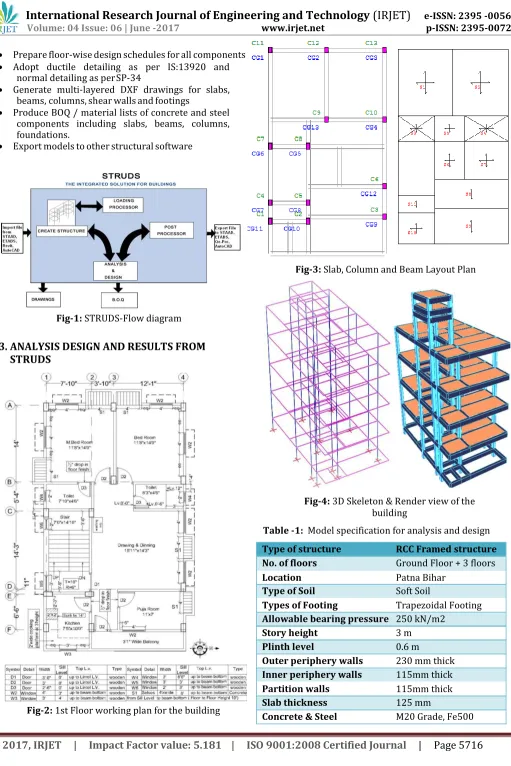
Fig-3: Slab, Column and Beam Layout Plan
[image:2.596.46.557.37.803.2]Fig-4: 3D Skeleton & Render view of the building
Table -1: Model specification for analysis and design Type of structure RCC Framed structure No. of floors Ground Floor + 3 floors
Location Patna Bihar
Type of Soil Soft Soil
Types of Footing Trapezoidal Footing Allowable bearing pressure 250 kN/m2
Story height 3 m
Plinth level 0.6 m
Outer periphery walls 230 mm thick Inner periphery walls 115mm thick Partition walls 115mm thick
Slab thickness 125 mm
Table -2: Live loads and EQ load
data
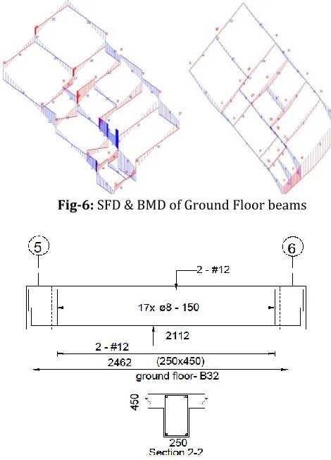
3.2 Beams
[image:3.596.298.556.185.738.2]In each floor there are totally 35 beams which comprises of both singly reinforced and doubly reinforced beams. Beam size of 250mm x 450mm is constant throughout the floor and the stirrups provided for all the beams are 4-Legged- 8mm diameter bars at 150mm c/c.
Table -4: Beam Reinforcement Details
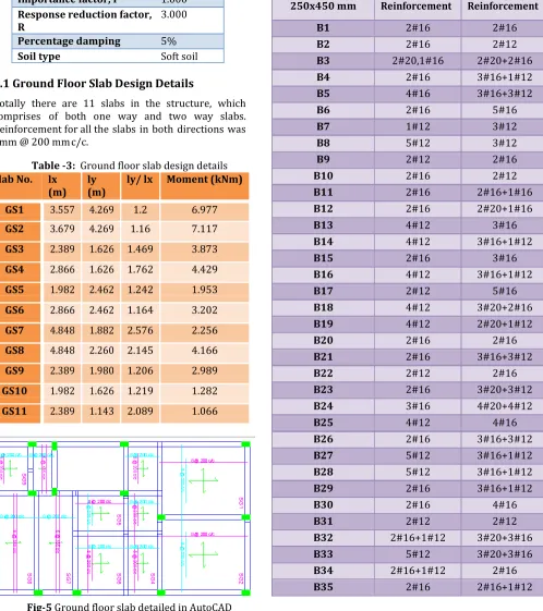
3.1 Ground Floor Slab Design Details
[image:3.596.53.551.195.756.2]Totally there are 11 slabs in the structure, which comprises of both one way and two way slabs. Reinforcement for all the slabs in both directions was 8mm @ 200 mm c/c.
Table -3: Ground floor slab design details Slab No. lx
(m) ly (m) ly/ lx Moment (kNm)
GS1 3.557 4.269 1.2 6.977
GS2 3.679 4.269 1.16 7.117
GS3 2.389 1.626 1.469 3.873 GS4 2.866 1.626 1.762 4.429 GS5 1.982 2.462 1.242 1.953 GS6 2.866 2.462 1.164 3.202 GS7 4.848 1.882 2.576 2.256 GS8 4.848 2.260 2.145 4.166 GS9 2.389 1.980 1.206 2.989 GS10 1.982 1.626 1.219 1.282 GS11 2.389 1.143 2.089 1.066
Fig-5 Ground floor slab detailed in AutoCAD
Floor Live load 3 kN/m2
Roof Live load 1.5 kN/m2
Floor Finish 1 kN/m2
Floor Finish (roof) 0.75 kN/m2
Wall load (External) 10.4 kN/m Wall load (Internal) 7.8 kN/m Seismic zone factor, Z 0.240 Importance factor, I 1.000 Response reduction factor,
R 3.000
Percentage damping 5%
Soil type Soft soil
Beam
250x450 mm Bottom Top
B1 2#16 2#16
B2 2#16 2#12
B3 2#20,1#16 2#20+2#16
B4 2#16 3#16+1#12
B5 4#16 3#16+3#12
B6 2#16 5#16
B7 1#12 3#12
B8 5#12 3#12
B9 2#12 2#16
B10 2#16 2#12
B11 2#16 2#16+1#16
B12 2#16 2#20+1#16
B13 4#12 3#16
B14 4#12 3#16+1#12
B15 2#16 3#16
B16 4#12 3#16+1#12
B17 2#12 5#16
B18 4#12 3#20+2#16
B19 4#12 2#20+1#12
B20 2#16 2#16
B21 2#16 3#16+3#12
B22 2#12 2#16
B23 2#16 3#20+3#12
B24 3#16 4#20+4#12
B25 4#12 4#16
B26 2#16 3#16+3#12
B27 5#12 3#16+1#12
B28 5#12 3#16+1#12
B29 2#16 3#16+1#12
B30 2#16 4#16
B31 2#12 2#12
B32 2#16+1#12 3#20+3#16
B33 5#12 3#20+3#16
B34 2#16+1#12 2#16
Fig-6: SFD & BMD of Ground Floor beams Fig-8: Columns detailed in AutoCAD (Cross section at ground floor)
3.4 Footing
[image:4.596.317.578.99.222.2]Totally there are 13 footings in the building. STRUDS has designed an isolated trapezoidal footing for all the columns. PCC bed thickness and the minimum depth of footing is 150mm. The footing dimensions and reinforcement details are tabulated in the table below.
[image:4.596.62.261.252.424.2]Table -6: Footing size and reinforcement details
Fig-7: Beam between grid 5 and 6 detailed in AutoCAD
3.3 Columns
Totally there are 13 columns in the building. The design details of all the columns are extracted. In table below complete column details of C13 column is mentioned. Similar details are obtained for all other columns also.
Table -5: Column size and reinforcement details for column C13
Foo ting
Col um n
PCC size
X-Y (mm)
Footing size
X-Y (mm)
Total Depth (mm)
Steel
II to X
Steel
II to Y
FG1 C1 2150X2300 1850X2000 700 12- #12 11- #12
FG2 C2 2525X2675 2225X2375 850 17- #12 16- #12
FG3 C3 2325X2475 2025X2125 750 14- #12 14- #12
FG4 C4 2000X2150 1700X1850 625 10- #12 9- #12
FG5 C5 2225X2375 1575X1725 725 12- #12 12- #12
FG6 C6 1875X2025 1925X2075 550 10- #12 9- #12
FG7 C7 2225X2375 1575X1725 725 13- #12 12- #12
FG8 C8 2475X2625 1925X2075 800 15- #12 14- #12
FG9 C9 2325X2475 2175X2325 725 13- #12 12- #12
FG1 C10 2150X2300 2025X2175 675 12- #12 11- #12
Colu
No.
Floo r-
el
Colu mn size (mm
Axia l Loa
d
Main
(mm
Later al ties
Ast Prov mm²
Ast Per
ct
FG1 C11 1775X1925 1850X2000 525 11- #10 8- #12
FG1 C12 1925X2075 1475X1625 575 10- #12 9- #12
FG1 C13 1350X1500 1625X1775 475 9- #10 8- #10
C13
GF 250 x
400 545. 77 #12 – 20 #8 @ 190 2262 2.26 1st
floor 250 x 400 456. 52 #12 - 14 #8 @ 190 1583 1.58 2nd
floor 250 x 400 327. 65 #12 - 12 #8 @ 190 1357 1.35 3rd
floor 250 x 400 201. 55 #12 - 10 #8 @ 190 1131 1.13 Roof 250 x
400 90.9 #12 - 10 #8 @ 190 1131 1.13
[image:4.596.238.580.362.735.2]© 2017, IRJET | Impact Factor value: 5.181 | ISO 9001:2008 Certified Journal
| Page 5719
4.
MANUAL DESIGN DETAILS
Table -7: Slab Design Comparison of SLAB-S2
Details STRUDS Manual calculation Maximum
moment 7.117 kN-m 5.472 kN-m Reinforcement
details (both direction)
8# @ 200
[image:5.596.43.263.246.345.2]mm c/c 8# @ 300 mm c/c
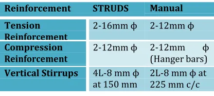
Table -8: Beam Design Comparison of BEAM-B2
Reinforcement STRUDS Manual Tension
Reinforcement 2-16mm ϕ 2-12mm ϕ Compression
Reinforcement 2-12mm ϕ 2-12mm (Hanger bars) ϕ Vertical Stirrups 4L-8 mm ϕ
[image:5.596.32.293.371.487.2]at 150 mm 2L-8 mm ϕ at 225 mm c/c
Table -9: Column Design Comparison of
COLUMN-C2
5. CONCLUSIONS
1. Manual design and analysis of structural elements of buildings is time consuming, it can be reduced by using software such as STRUDS.
2. AutoCAD plans can be easily imported to STRUDS. 3. Detailed report of analysis and design of all the
structural elements can be obtained.
4. The advantage of STRUDS is that the detailing of the structural elements can also be obtained as an AutoCAD file report.
5. The design values of the structural elements as obtained from STRUDS are slightly on higher side compared to the manual design calculation.
REFERENCES
[1] G. Divya Rani, Satya Shiva Prasad, “Design of Residential Apartment Building by using Struds”, International journal of scientific engineering and technology research, ISSN 2319-8885 Vol.04, Issue.33, August-2015, Pages:6724- 6725.
[2] Satish Dangeti, Ramesh Surisetty, Global J. of Engg. & Appl. Sciences, 2012: 2 (3) Research Paper, Suresh, 2012:
Pp.275-277
[3] IS:875-Part I-1987 –Code of Practice for Design load (Dead load)
[4] IS:875-Part II -1987 -Code of Practice for Design load (Live Load)
[5] IS:1893-2002-IV –Criteria for earthquake resistant design of structures.
[6] IS:456-2000 Plain and Reinforced concrete- Code of Practice.
[7] SP-16 –Design aid for Reinforced concrete to IS-456-197
Table -10: Footing Design Comparison of FOOTING -FG2
Details STRUDS
(Trapezoidal footing)
Manual Design (m)
Square footing
Footing
Dimension 2.225 x 2.375 x 0.85 (Depth minimum of 150mm)
2.85 x 2.85 x 1.4
Reinforcement 1709 mm2
17- #12 Parallel to X
16 - #12 parallel to Y
1608 mm2 (16 mm
ϕ bars @ 125 mm c/c in both directions)
15- #16 in both directions
Details STRUDS Manual Design
Column 325 mm x 475 mm 250 mm x 400 mm
Longitudinal 2840 mm2
(18-12 mm ϕ + 4- 16 mm ϕ)
2945.24 mm2
6- 25mm ϕ
Lateral ties