© 2018, IRJET | Impact Factor value: 6.171 | ISO 9001:2008 Certified Journal | Page 4273
RETROFITTING OF REINFORCED CONCRETE
BEAMS WITH HPFRCM
STRIP COMPARED WITH GFRP
Sarath kumar M
Student, Master of Engineering in Construction Engineering and Management
Department of Civil Engineering, Meenakshi Sundararajan Engineering College, Chennai, Tamil Nadu, India
---***---Abstract
:
The maintenance, rehabilitation and upgrading ofstructural members, is perhaps one of the most crucial problems in civil engineering application. A new retrofitting technique based on a material compatible with concrete is currently under development. It overcomes some of the problems associated with the current techniques based on extremely bonded steel plates and FRP laminates which are due to the mismatch of their tensile strength and stiffness with that of the concrete structure being retrofitted.In order to overcome the limitations of current retrofitting technique an attempt has made to develop a High performance Fiber reinforced cementitous mix in a form of an strip say about 12 to 16 mm thick which is then attached with the controlled beam(which undergoes an 75% Preloading) by means of an strong Epoxy and Hardner mix. By these mean the strip has been placed at various position (i.e. tension face, Tension face and on other vertical sides, tension face and on four rectangular vertical sides.) which is then checked for Flexural, shear and deflection pattern has also be tested using the loading Frame.
Keywords: Retrofitting, HPFRCM, Adhesive, Steel Fibers, GFRP.
1. INTRODUCTION
Existing Concrete structures may, for a variety of reasons, be found to perform unsatisfactorily. This could manifest itself by poor performance under service loading, in the form of excessive deflections and cracking, or there could be inadequate ultimate strength. . Moreover, a large number of structures constructed in the past using the older design codes in different parts of the world are structurally unsafe according to the new design codes. Since replacement of such deficient elements of structures incurs a huge amount of public money and time, strengthening has become the acceptable way of improving their load carrying capacity and extending their service lives. Infrastructure decay caused by premature deterioration of buildings and structures has led to the investigation of several processes for repairing or will be on One of the challenges in strengthening of concrete structures is selection of a strengthening method that will enhance the strength and serviceability of the structure while addressing limitations such as constructability, building operations, and budget. Structural strengthening may be required due to many different situations. Additional strength may be needed to allow for higher loads to be placed on the structure. This is often required when the use of the
structure changes and a higher load-carrying capacity is needed. This can also occur if additional mechanical equipment, filing systems, planters, or other items are being added to a structure. Strengthening may be needed to allow the structure to resist loads that were not anticipated in the original design. The main objective is to study and compare the behaviour of RC beams. The majority of structural strengthening involves improving the ability of the structural elements to safely resist one or more internal forces caused by loading such flexural shear etc. Strengthening is accomplished by either reducing the magnitude of these forces. Hence this project aim is to retrofit the RC beams using Glass Fiber reinforced concrete and using High performance fiber reinforced cementitous mix strip, therefore retrofitting of concrete provides economical and technical alternative to traditional techniques in many situations, because of its increased strength, high fatigue resistance easy and rapid installation.
2. HPFRCM
The aim was to achieve a good workable mix with a very low water/ blinder ratio and a high volume fraction of steel fiber, in order that the resulting material, in its hardened state, will be ductile with a relatively high tensile strength. As a result of many trial mixes and testing, the mixes shown in Table 1.
Constituent (kg)
Mix 1 Mix 2
Cement 7.016 7.016
Micro silica 0.701 1.403 Quartz sand 35.04 35.04
Water 0.051 0.051
[image:1.595.357.515.510.630.2]Fibres 3.744 5.832
Table 1: Mix Proportion for HPFRCC Strip Mix
Since these Mix values are arrived based on the IS specification 92 of mortar Mix in a ratio of 1:6. Where Micro silica for Mix 1 is takes as a 10% of the Quantity of cement and for Mix 2 it is 20% of cement.
© 2018, IRJET | Impact Factor value: 6.171 | ISO 9001:2008 Certified Journal | Page 4274 A volume Fraction of `30% (both short and long Fiber) for
mix 1 and mix 2 is added. Similarly a volume fraction of 20% is added for Mix proportion 3. The specimen was hot-cured @ 450 C for seven days. The strength attained have been found to be equivalent of standard 28-day water curing at 20oC.
3. TEST BEAMS
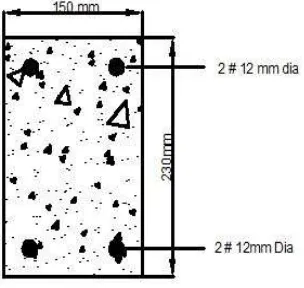
Three sets of beam were casted for this experimental test program. IN SET I three beams (C1, C2, and C3) were casted using M30 grade of concrete and reinforcing detailing. In SET II four beams (GF1, GF2, GS1, and GS2) out of which two were weak in flexure and two were weak in shear using the same grade of concrete and reinforcing detailing. In SET III eight beams (S1F1, S1F2, S1S1, S1S2, S2F1, S2F2, S2S1, and S2S2) were casted. The dimensions of all the specimens are identical. The cross sectional dimensions of all the three SET of beam is 1000mm by 150mm by 230mm. For SET I 2 beams, 12mm Dia bars are provided as the longitudinal reinforcement both at tension and compression side and 8mm Dia bars as stirrups at a spacing of 150 mm centre to centre. For SET II two beam is provided with shear i.e. with stirrups and two without stirrups. Whereas for SET III four beams is provided with stirrups and four without stirrups as detailed in fig. 1
[image:2.595.90.234.398.531.2]Fig 1: Cross sectional view of the beam weak in Flexure
Fig 2: Cross sectional view of the beam weak in Flexure
The detailed description of the beam was listed below in the table 2.
S. NO
Type of Beam Beam Designation
1 Controlled beam C1
2 Controlled beam C2
3 Controlled beam C3
4 GFRP at the soffit of the beam
F1
5 GFRP up to neutral axis
F2
6 GFRP only on the two vertical side
S1
7 GFRP as U-wrap S2
8 STRIP at the soffit of the beam Mix 1
F3
9 STRIP up to neutral axis Mix 1
F4
10 STRIP only on the two vertical side Mix
1
S3
11 STRIP as U-wrap Mix 1
S4
12 STRIP at the soffit of the beam Mix 2
F31
13 STRIP up to neutral axis Mix 2
F41
14 STRIP only on the two vertical side Mix
2.
S31
15 STRIP as U-wrap Mix 2.
S41
Table 2:Type of beams casted
Where,
S – Beam weak in shear (without Shear reinforcement).
[image:2.595.92.244.581.725.2]© 2018, IRJET | Impact Factor value: 6.171 | ISO 9001:2008 Certified Journal | Page 4275
4. CUBE SPECIMENS
Before the beam were casted the test cube were made for M30 grade concrete and the High Performance Fiber reinforced cementitous mix. The mix design calculations were made based on the IS code.
[image:3.595.339.531.147.243.2]The aggregates used are 12mm and the cement of 53 grade OPC. The cubes are then cured and tested in the CTM after 14days and 28 days as shown in fig 5, 6,7.
[image:3.595.70.256.203.303.2]Fig 3: Conventional Concrete cube
[image:3.595.66.259.333.445.2]Fig 4: High Performance Fiber Reinforced Strip
Fig 5: Testing of Cube in CTM
5. FABRICATION OF GFRP
A flat plywood rigid platform was selcted. A thin film of ployvinyl alcohol is applied on the platform as a releasing agent. The Glass Chopped sheet is placed over the plywood platform. Laminating starts with the process of gel coat (Epoxy and Hardner) deposited on the sheet, whose main purpose was to provide a smooth external surface and to protect the fiber from direct exposure to the environment. Layer of sheet is again placed over it and again epoxy and hardner mix is applied over it. A hand roller is used to remove all the air bubbles from the sheet. The sides are cut
down for even finish. The process is continued until the required thickness of 3mm is achieved Then, a heavy meal rigid platform was sheet on top of the sheet for the compression purpose. These are left for a minimum of 48 hours before testing as shown in fig 8,9.
Fig 6: Material required for GFRP fabrication
[image:3.595.325.543.409.536.2]Fig 7: Application of Polyvinyl as releasing agent
Fig 8: Removal of air bubbles using roller
[image:3.595.66.258.473.598.2] [image:3.595.326.538.600.746.2]© 2018, IRJET | Impact Factor value: 6.171 | ISO 9001:2008 Certified Journal | Page 4276
GFRP 4.9 345 14020
Table 3:Load carrying capacity of GFRP
Fig 9: Experimental Setup of INSTRON
Determination of Ultimate load, Ultimate stress and young’s modulus
Ultimate Load
KN
Ultimate Stress MPa
Young’s modulus
MPa
6. Aspect Ratio for steel Fiber
Fiber used: Crimped & Hooked Type
Volume Fraction Vf should be 10 to 30 %
Aspect ratio = Length of fiber/ɸ of fiber
Length & ɸ of fiber: 30 & 0.40 mm
Hence Aspect ratio = 75
For aspect ratio 75,
Relative density = 1.70
Relative Toughness = 10.5
7. CASTING OF STRIPS
[image:4.595.287.578.54.518.2]The retrofit materials, HP strip Mix 1, Mix 2 were cast in 800mm long and 150 mm wide wooden moulds with a well-oiled base and raised border whose height could be adjusted to give 12mm thick plates. The moulds were rolled on a vibrating table at 50 Hz frequency and smoothed over. To ensure a uniform thickness a glass panel was located on top of the raised border. The strips were left to cure in the moulds for 24 h at 30oc before demoulding. The retrofitted strips were cured for 10 days.
Fig 10: Demoulding of the Strip
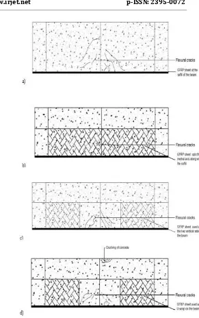
Fig: 11. a) GFRP placed on the soffit of the beam
b) GFRP placed on the neutral axis along with the soffit of the beam
c) GFRP placed on the two vertical sides of the beam
[image:4.595.50.274.609.735.2]© 2018, IRJET | Impact Factor value: 6.171 | ISO 9001:2008 Certified Journal | Page 4277 Similarly,
Fig: 12. a) Strip placed on the soffit of the beam
b) Strip placed on the neutral axis along with the soffit of the beam
c) Strip placed on the two vertical sides of the beam
d) Strip placed in form of U-wrap
8. RESULT ANALYSIS
9. LOAD DEFLECTION HISTORY
The load deflection history was recorded. The mid span deflection of the beam is compared with that of respective control beams. It has been noted that load deflection pattern of the beam wrapped with strip better than that of the beam wrapped with GFRP and the controlled beam. The graph compared the deflection pattern of the controlled, GFRP and HPFRCM strip.
10. CONCLUSION
© 2018, IRJET | Impact Factor value: 6.171 | ISO 9001:2008 Certified Journal | Page 4278 the high performance fiber reinforced strip is 48% more
than that of the controlled beam and at the same time 20 % more than that of the GFRP fiber.
ACKNOWLEDGEMENT
I express my gratitude to God for giving me knowledge to complete this work in proper manner. I would also like to thank my assistant professor Miss. N. Sivaranjani for directing me to complete my work successfully.
References
I. IS 456 (2000) Plain and reinforced Concrete. II. IS 800 Practise Of Reinforced Steel
III. IS 10262:2009- Concrete Mix Proportioning. IV. IS 15388- Specification for Silica Fume
V. IS 1917 part3 – Chemical analysis of Silica Sand. VI. Abhjith Mukherjee 2016 New Repair and
Rehabilitation Technologies for Masonry Buildings. International Journal of engineering and science. Vol.7, Issue 4 ISSN(online): 2319-6734.
VII. Akshayp. Giel et al 2016 from Mahaidol University A Case Study on the Use of Advanced Fiber Wrap Composites for Reinforced Concrete Repair of an Industrial Coker Reinforced Concrete Frame. Journals of Japan concrete institution. Vol.4, Issue 7, pp.142-145.
VIII. Azadehehparvin 2015 from W.T Josep Islamic university Fatigue Strengthening of cracked steel beam with different Configurations and material. International journal of innovative science & technology. pp. 3127
IX. Benson, S.D.P., Karihaloo, B.L.: CARDIFRC — Development and mechanical properties. Part III: Uniaxial tensile response and other mechanical properties. Mag. Concr. Res. 57, 433–443)
X. Bilal S. Hamad et al Bond Studies of High-Strength Concrete Joints Confined with Stirrups, Steel Fibers, or Fiber-Reinforced Polymer Sheets. American Society of Civil Engineering. Vol.4, Issue 6, pp.122-185.
XI. Bing Li et al 2012 Retrofitting Earthquake-Damaged RC Structural Walls with Openings by Externally Bonded FRP Strips and Sheets. American Society of Civil Engineering. ISSN(online): 2319-6734.
XII. Bonneau, O., Poulin, C., Dugat, J., Richard, P., Aitcin, P.: Reactive powder concretes: from theory to practice. Concr. Int. 18, 47–49.
XIII. Chris P. Pantelides et al 2010 Effectiveness of Repair and Strengthening Methods for Reinforced Concrete Columns and Beam-Column Joints International journal of innovative science & technology. Vol.4, Issue 6, pp.122-185.
XIV. Hamdy M. Mohame et al., (2008) Shear strengthening of RC beam with externally Bonded CFRP sheets.
XV. Farshid Jandaghi Alaeeet al., (2008) Retrofitting of Reinforced.
XVI. Karihaloo, B.L., Benson, S.D.P., Alaee, F.J.: Cementitious mixtures and a method of production thereof. UK Patent GB2391010 (2007)
XVII. Nicolaides, D., Kanellopoulos, A.D., Karihaloo, B.L.: Fatigue life and self-induced volumetric changes of CARDIFRC. Mag. Concr. Res. 62, 679–683 (2006)
XVIII. Reyes Garci et al 2006 Seismic Strengthening of
Severely Damaged Beam-Column RC Joints Using CFRP American Society of Civil Engineering.
XIX. A.S Samer et al 2002 Normal- And High-Strength Fiber-Reinforced Concrete under Compression. International Journal of engineering and science. ISSN(online): 1115-1125
XX. Yang Yang et al 2001 Seismic Repair of Reinforced Concrete Bridge Columns. American Society of Civil Engineering. Vol.6, Issue 5, pp.342-485.
AUTHOR:
Sarath kumar M, Student Master of Engineering,
(Construction engineering and management)