© 2017, IRJET | Impact Factor value: 6.171 | ISO 9001:2008 Certified Journal | Page 1994
Design and Analysis of Fixture for component cradle in HMC-800
Lokesh
1, Ambadas
2, Babu Reddy
31
M.Tech. Student, Department of Machine Design, VTU PG Centre, Kalaburagi-585105 Karnataka, India.
2Assistant Professor & Course coordinator, Department of Machine Design VTU PG Centre, Kalaburagi-585105
Karnataka, India.
3
Assistant Professor, Department of Machine Design VTU PG Centre, Kalaburagi-585105 Karnataka, India.
---***---Abstract -
Main objective of project work is to design a fixture which can used with horizontal machine center 800, for manufacturing a cradle component. Here fixture is designed such that it should hold, support and guide the cradle component, where different machining operation is carried out. Firstly individual component of fixture is designed and assembly is done in solid works. ANSYS software is used for evaluation of stress and displacement of critical parts and same parts are also analyzed by analytical method. Finally comparative study is carried out.Key words: Horizontal Machining Centre-800, Solid works, and Ansys Software.
1. INTRODUCTION
Now a day, the small scale industries are trying to increase the demand of the product and increase the mass production. To meet these challenges it has become very important for companies to increase their production rate. The successful running of any mass production depends upon the interchangeability of the work parts to facilitate easy assembly and reduction of unit cost. Mass production demands a fast and easy method of positioning work for accurate operation on it. The main intention of any company is to provide good quality product and increase in production rate in order to get profit over it. This can be achieved by minimizing manufacturing lead time and cost of production by using work holding guiding device. This work holding device is fixture. Fixture word is derived from latin word which means fixed or attached.
Fixtures are designed such that large number of components can be machined or assembled identically. Fixtures are special purpose tools which are used to facilitate production when work piece are to be produced in mass production scale. Advantages of fixtures are, once the fixture is properly setup, any number of duplicate parts can be readily produced without any additional setup. Hence increasing the productivity and increasing accuracy by reducing setup cost and manual fatigue.
It is a device for locating, holding and supporting a work piece during a Manufacturing operation. Fixtures are essential elements of production processes as they are required in most of the automated manufacturing, inspection, and assembly operations.
1.1 Purpose of Fixture
The main purpose of the fixture is to locate the work piece quickly and accurate, Support it proper and hold it securely, thus ensures that all parts produced in the fixture will come out alike within the specified limits. In this way accuracy and inter changeability of the parts are provided.
By maintaining or even improving the inter changeability of the components, the fixtures help to significantly reduce assembly costs, maintenance costs, and the potential of subsequent standard machines, and the quality of the parts. An important goal is to design a fixture that makes it very convenient and adds security to the operator as well as to the machine and other used components.
1.2 Classification of Fixtures
Generally, all fixtures consist of the following elements: a) Locators b) Clamp c) Supports d). Fixture body Fixtures are classified according to following factors.
Application Based 1. Work holding fixtures 2. Tool holding fixtures 3. Fit- up fixtures 4. Gauging fixtures 5. Holding fixtures
Based On Degree of Mechanization and Automation 1. Hand operated
2. Power operated 3. Semi-automatic 4. Automatic Based On Operation 1. Milling fixtures 2. Drilling fixtures 3. Turning fixtures 4. Grinding fixtures 5. Broaching fixtures 6. Welding fixtures 7. Assembly fixtures
© 2017, IRJET | Impact Factor value: 6.171 | ISO 9001:2008 Certified Journal | Page 1995
1.4 Materials Used In Fixture
The materials used in fixture are –
1. High-speed steel: Mainly used for cutting tools, such as drill bits, reamers and Cutting cutter. These can be oil or hardened to 64 to 66 Rc.18% tungsten and 22% tungsten HSS also contains 4.3% chromium 1.6% vanadium and less carbon, molybdenum and so on.
2. Die steel: These are mainly used for hot working or cold working moulds, die steel for stamping tools that can be hardened to 65RC, which contains about 1% carbon, 0.5 to 1.5% tungsten and a small amount of silicon, hardening. Mold steel for extrusion, forging and die casting mold, due to hot processing and subject to high temperature. These are usually oil/air hardened to 40 to 50 RC, containing 2-5% chromium, 4-9% tungsten, 0.4-0.5% vanadium and a smaller amount of manganese and silicon.
3. Carbon steel: These can be used for standard cutting tools. They contain 0.85% carbon, 0.5-0.8% manganese and a smaller amount of silicon. These can be hydrated to 62 to 63% of the RC. The steel can be used for drill bushings, locators and other parts that are worn and require hardening.
4. Cast Iron: Used for processing and piecing the odd shape when manufacturing, CI need to use casting mode. The cost of the model should be compared with the processing and manufacturing costs. Iron content of more than 2%, can withstand vibration is very suitable for milling base and body. The self-lubricating property of cast iron is suitable for machine rails.
5. Non Shrinking tool steels: This is also known as high carbon (1-2%) or high chromium (4-12%) steel. These steels are distorted during heat treatment and are easy to handle when they are not possible to eliminate heat treatment distortion. Oil is hardened to 60-64 RC. These steels are widely used in fine, complex pressure tools.
1.5 Objective
The objective of this project is
Design and manufacturing of individual parts and assembly of fixture for a cradle component.
Fixture is designed such that it is only suitable for horizontal machining Centre (HMC-800).
Initial design of a fixture is done as per require size of cradle component.
The fixture has to be designed for holding and guiding the cradle component while performing the drilling, facing, milling, tapping operation on it.
Analytical calculation of fixture design is compared with numerical values.
1.6 Methodology
Study of the cradle component and the existing fixture in use.
Fixture planning: Estimation of the process for achieving the final dimensions of the components, analyzing all the available information regarding the material, geometry of the cradle component and operations required. Fixture layout is to represent the fixture concepts in a
physical form. i.e. Positions of locators, Positions of clamps, Positions of supports and sequence.
Fixture element design: The fixture design has been done using modeling software solid works.
Fixture assembly design: after completion of designing individual part of the fixture, fixture assembly has been carried out.
After completion of fixture design, casting and machining has been carried out for all the individual parts.
Using the machining parameters, the force exerted on the component is calculated. The analytical formulas are used to calculate stress and deformation for critical parts.
Analysis of critical components: The static analysis is carried out by finite element method using ANSYS software to find out stress and deformation.
Analytical results for critical parts are validated with FE analysis and found good results.
2. LITERATURE REVIEW
N. P. Maniar and D. P. Vakharia, HMC is best solution for particular component but designer can’t ask industries to replace CNC with HMC because of the cost factor, as HMC cost more than CNC. With the help of creo element/ proe5.0 the unbalance mass and its location of C.G are found out and it is remarkably same as experimental result on dynamic balancing machine. So, Computer aided mass balancing of quadrants is found more accurate to decrease in percentage error by almost 6%. [1]
C. Radha Madhavi, K. Srinivasulu.et al this project presents the design of fixture for gas turbine rotor blade for machining on VMC (Vertical Machining Centre). This report consists of study of input data from customers like part drawing and assembly drawing. The fixture design begins with part modeling, machining and analysis of various parts in the fixture assembly using solidworks, for an analysis COSMOS software package is used. [2]
© 2017, IRJET | Impact Factor value: 6.171 | ISO 9001:2008 Certified Journal | Page 1996 fabrication of fixture and is tested for its productivity. From
static analysis maximum cutting force and maximum clamping force are found. Maximum static deflection and maximum stress are also found. [3]
P. Satish Reddy and V. Subrahmanyam In this paper, the design requirements of the fixture were studied, customers are using horizontal machining center for parts processing. Their concept is to place the components vertically on the machine. To this end, they choose the welding structure. Complete the analysis of the clamp to check whether the fixture is subjected to the maximum cutting force during machining. [4]
3. DETAILS OF FIXTURE FOR COMPONENT CRADLE
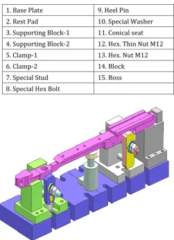
Solid work has been used to sketch 2D daigram of fixture for component cradle. Later on 2D sketch is converted into 3D modelling in the solid work and assembly has been done. Individual parts of fixture is given below.
1. Base Plate 9. Heel Pin
2. Rest Pad 10. Special Washer
3. Supporting Block-1 11. Conical seat 4. Supporting Block-2 12. Hex. Thin Nut M12
5. Clamp-1 13. Hex. Nut M12
6. Clamp-2 14. Block
7. Special Stud 15. Boss
[image:3.595.308.564.97.309.2]8. Special Hex Bolt
[image:3.595.34.286.343.690.2]Figure 1: Isometric View of Assembly of Fixture with Component
Figure: 2 Horizontal Machining Center-800
3.1 Analytical Calculation and FE Analysis
3.2 Force calculations for Drilling:Following specification of drilling operation are used to calculate the cutting force in HMC machine.
Speed 2100 RPM
Drill Diameter Ø13mm
[image:3.595.41.481.343.769.2]Feed Per Revolutions 0.05-0.06 mm/Rev
Table 1: Specification of drilling operation
Cutting Speed: (m/min)
V = π D n /1000
V = (π x 13 x2100)/1000 V = 85.76
Power at the Spindle: (KW)
N = 1.25 x D2 x k x n (0.056 + 1.5 x s) /105
= 1.25 x (13)2 x 2100 x 2.1 x (0.056+1.5 x 0.05)/105
N = 1.222
Power at the Motor: (KW)
Nel = N/E
= 01.220/0.8 Nel = 1.525
Torque at Spindle: (N-m)
Ts = 975 x N/n
© 2017, IRJET | Impact Factor value: 6.171 | ISO 9001:2008 Certified Journal | Page 1997 Cutting Force: (N)
Tf = 1.16 x K x D (100 x s) 0.85
= 1.16 x 2.1 x13 (100 x0.2)0.85
Tf = 1243.78
Analytical Calculation For support Pin
Force F=1243N
Area: (mm2) Deformation: (mm)
/4 /4 = 962.11
/4 /4 = 314.15
/4 /4 = 1256.6
= FL/AE
= F/E [(L1/A1) + (L2/A2) + (L3/A3)]
= 400/2 105 [(10/962.1)
+(19/314.15) + (46/1256.6)] = 2.14 10-4
AT = 2532.86 = 2.14 10-4
Stress: (MPa) σ = F/A
σ = F [(1/A1) + (1/A2) + (1/A3)]
σ = 400[(1/962.11) + (1/314.15) + (1/1256.6)] σ = 2
3.3 FE ANALYSIS
In the static structural analysis, the displacements and stresses, due to external force are determined. There are two kind of structural analysis; one is linear structural analysis and another one non-linear structural analysis.
3.4 Material Properties
For the fixture, the material considered in the analysis is Steel. The mechanical properties of the Steel are shown in below.
Properties Steel
Young’s modulus 2.0E+05 MPa
Poisson’s ratio 0.3
Density 7850 kg/m3
Yield strength 250 MPa
[image:4.595.31.286.211.454.2]Tensile Ultimate strength 400 MPa
Table 2: material properties of steel
Support pin:
The model is constrained at the bottom surface of base structure and force is applied at the top portion as shown in below figure.
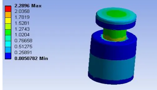
Figure 3: Support pin
Figure 4: Displacement plot
[image:4.595.315.566.572.716.2]The displacement of support pin is shown in above figure. The maximum static deflection of support pin is found to be 3.0092 10-4 mm.
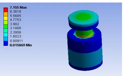
Figure 5: Stress plot
© 2017, IRJET | Impact Factor value: 6.171 | ISO 9001:2008 Certified Journal | Page 1998 Figure 6: von-Mises stress plot
The von-Mises stress of support pin is shown in figure 30. The maximum von-Mises stress of support pin is found to be 7.155Mpa.
Component Name
Theoretical Results FEA Results
Deflection
(mm) Stress (Mpa) Deflection (mm)
Stress (Mpa)
Support
Block-1 1.51 10-4 1.559 1.834 10-4 1.0185
Support Pin 2.14 10-4 2.01 3.0092 10-4 2.2896
Support
[image:5.595.36.283.94.246.2]Block-2 4.636 10-5 0.238 5.6 10-5 0.32135
Table 3: Comparison of Theoretical and FEA Results
4. CONCLUSION
The fixture for cradle component has been designed successfully, in order to increase the accuracy and productivity.
The cutting forces were calculated for all machining operation. The maximum cutting force in drilling operation i.e.1250N.
The static analysis is carried out by finite element method using ANSYS software.
Analytical results for critical parts are validated with FE Analysis and found relatively good results.
The maximum static deflection, stress and von-Mises stress is found in support block-1 i.e. 1.834 10-4
mm, 1.08 MPa and 3.1608 MPa. These values are within the design limits.
The maximum static deflection, stress and von-Mises stress is found in support pin i.e. 3.0092 10-3 mm,
2.289 MPa and 7.155MPa. These values are within the design limits.
The maximum static deflection, stress and von-Mises stress is found in support block-2 i.e. 5.6 10-5 mm,
0.3215 MPa and 3.08 MPa. These values are within the design limits.
ACKNOWLEDGEMENT
I wish to express my sincere thanks & gratitude to thank my parents, teachers & all people who have helped me directly or indirectly for the completion of this project work. I hereby acknowledge with deep sense of gratitude the valuable guidance, encouragement and suggestions given by my M.Tech project guide Mr. Ambadas Assistant Professor & Course coordinator, Dept. of Machine Design VTU PG Centre kalaburagi, Karnataka.
REFERENCES
[1].Vaibhav S Warule and Suresh M Sawant “Design and analysis of milling fixture for HMC” Journal of basic and applied engineering research, ISSN: 2350-0077, Volume 2, November 16; April-June, 2015.
[2]. C. Radha Madhavi, B. Ramu and K. Srinivasulu “ Design of machining fixture for turbine rotor balde” IJRET, PISSN: 2321-7308.
[3]. Dr. Yadavalli Basavaraj and Pavan Kumar B K “Design and analysis of support pin for brake spider fixture by FEM using ansys software” IOSR e-ISSN: 2278-1684 Volume 6, Issue (Mar.-Apr.2013).
[4]. Machine Design Data handbook, Central machine tools Institute (CMTI), Bengaluru.
[5]. Machine Design Data Handbook, Tata McGraw Hill. pp. 658-660.
[6]. Krishna Kumar Kulankara, SrinathSatyanarayana and Shreyes N. Melkote, 2002. By using genetic algorithm, describes Optimization of clamping force and Fixture layout. ASME Journal, 124: 119-125
[7]. Kailing Li Ran Liu Guiheng Bai, “Development of an intelligent jig and fixture design system”, Computer-Aided Industrial Design and Conceptual Design, 2006. CAIDCD '06.pp 1-5.