© 2017, IRJET | Impact Factor value: 5.181 | ISO 9001:2008 Certified Journal | Page 1809
DESIGN OF SINGLE PHASE AUTOMATIC POWER FACTOR CONTROLLER
USING MICROCONTROLLER
Vaibhav Yeole
1, Shubham Dhurve
2, Sanket Sure
3, Ashvini Meshram
4,
Tushar Nawale
5,
Mr. Mohammad Ashar
61
Vaibhav Yeole, Electrical Engineering, S.B.J.I.T.M.R., Maharashtra, India
2Shubham Dhurve, Electrical Engineering, S.B.J.I.T.M.R., Maharashtra, India
3
Sanket Sure, Electrical Engineering, S.B.J.I.T.M.R., Maharashtra, India
4Tushar Nawale, Electrical Engineering, S.B.J.I.T.M.R., Maharashtra, India
5Ashvini Meshram, Electrical Engineering, S.B.J.I.T.M.R., Maharashtra, India
6
Prof. Mohammad Ashar, Dept. of Electrical Engineering, S.B.J.I.T.M.R., Maharashtra, India
---***---Abstract -
In the present scientific revolution, power is veryvaluable. So we need to find out the cause of power loss and develop the system. Due to increase in use of inductive load, power system losses its efficiency. So we need to improve the power factor with a suitable method. Automatic power factor improvement device reads power factor from line voltage and line current by defining the delay in the arrival of the current signal with respect to voltage signal from the zero cross detector with high correctness by an internal timer. This time values are then calibrated as phase angle and consequential power factor. Then the microcontroller calculates the compensation necessity and consequently switches on to different capacitor banks. Automatic power factor improvement methods can be applied to the industries, power systems and also household to create them stable and due to that the system becomes steady and hence increases efficiency of the system.
Key Words: Inductive Load, Power Factor, Zero Cross Detector, Microcontroller, Capacitor Bank.
1.INTRODUCTION
“POWER FACTOR is the ratio of useful (true) power whose unit is KW to the total (apparent) power whose unit is KVA”. Automatic power factor controller project is planned to improve power factor automatically, whenever power factor falls below convinced level [4]. As we know that the requirement of electrical energy is increasing day by day, more and more inductive loads are increasing in industries as well as for household purpose [3]. Inductive loads are the main reason for low power factor in power system. There are more other problems occur if power factor is low [5]. They are
A) Additional losses in feeder cables B) Important voltage drop
C) Reduction of effective capacity of cables D)Voltage fall at the secondary of the transformer E) Losses in transformer
The Automatic Power factor improvement device is a very helpful device for improving efficient transmission of active power. If the consumer connect inductive load, then the power factor lags, when the power factor goes below 0.95(lag) then the Electric supply company charge penalty to the consumer. So it is important to sustain the Power factor below with in a limit. Automatic Power factor improvement device reads the power factor from line voltage and line current, calculating the compensation requirement switch on different capacitor banks.
This paper focuses on the implementation of power factor correction using microcontroller. Low power factor Includes needless burden on power system and transmission line. By improving power factor of power system automatically, power system efficiency can be better [1].
2. BLOCK DIAGRAM WITH DESCRIPTION
© 2017, IRJET | Impact Factor value: 5.181 | ISO 9001:2008 Certified Journal | Page 1810 Microcontroller
ATmega 16
Drives & Relay
Capacitive Bank LCD
ZCD (V)
ZCD (I)
[image:2.595.332.539.311.378.2]Load
Figure 1. Block diagram of APFC
3. METHODOLOGY
3.1
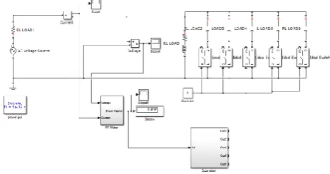
Simulink ModelIn this simulation we have used the AC voltage source of 230V and 50 Hz frequency and current block is connected in series with AC voltage source and voltage is connected in parallel. In this we have designed a power factor meter as shown in figure 3 to show the value of power factor via display. This power factor meter consists of two integrator. Then we have taken the difference of two integrator i.e. voltage and current. The difference come out to be in (msec.) but our actual concern is to find power factor. So we want the difference in degree therefore we have multiply the difference (msec.) into gain (2πf). Then the difference comes out to be in degree from this we found power factor i.e. 0.3037. For improving the power factor we have added the three capacitor bank across load then the power factor comes out to be 0.4034. Then we have added two capacitor parallel from this we get desired power factor i.e. 0.92 is as shown in figure 2. Then we have added relay in series with capacitor across the load. When the inductive load is ON the power factor decrease now the microcontroller energize the relay coil in order to compensate the unnecessary reactive power hence we get improve power factor automatically i.e. is as shown in figure 4.
[image:2.595.309.541.439.561.2]Figure 2.
Simulink Model with Capacitor Bank
Figure 3.
Simulink Model of Power Factor Meter
Figure 4.
Simulink Model using Capacitor and Relay
The methodology on which the paper id based consists of the following main parts.
A. Power Supply
: A bridge rectifier connected across main
© 2017, IRJET | Impact Factor value: 5.181 | ISO 9001:2008 Certified Journal | Page 1811 Figure 5. Power Supply
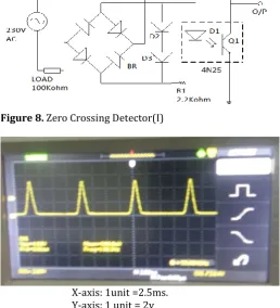
B. Zero Cross Detector (ZCD):
The current and voltage [image:3.595.308.567.145.430.2]signal are measured from the AC line using zero cross detector voltage circuit (ZCD V) and arrangement of zero cross detector current circuit(ZCD I) is as shown in figure6 & figure 8.These zero cross detectors individually converts both current and voltage waveforms to pulse wave and zero crossing detector of both voltage and current is as shown in figure 7& figure 9.
Figure 6.
Zero Crossing Detector(V)
X-axis: 1unit =2.5ms
Y-axis: 1unit =2v
Figure 7. Waveform of Zero Crossing Detector(V)
Figure 8. Zero Crossing Detector(I)
X-axis: 1unit =2.5ms. Y-axis: 1 unit = 2v
Figure 9. Waveform of Zero Crossing Detector(I)
C. Capacitor and relay matrix
: When load is connectedthe power factor is calculated by the microcontroller. If the calculated power factor is less than 0.95 then the relay switches on the capacitor. The below figure 10.Shows relays are switching using ULN2803 which is basically a driver IC. Current lead in capacitor compensates the consequent current lag which is typically present in loads. Hence phase difference between the current and voltage will be reduced. power factor correcting capacitor connected parallel to load through relay, if the relay is energized by microcontroller it will connect the capacitor parallel with load, if relay de-energized it will eliminate the capacitor from load. When the resistive load is on the power factor will be near to unity so the microcontroller does not energize the relay coil. When the inductive load is on the power factor decrease now the microcontroller energize the relay coil in order to compensate the unnecessary reactive power. Hence according to the load the power factor is corrected.
7805
230V AC MAINS INPUT
4*1N4001
470 uF
Regulation Smoothing
Rectification Transformer
IN 1 3 OUT
2 GND +5V
5V DC REGULAT
ED OUTPUT 0.1uF 0.1 uF
[image:3.595.35.281.400.700.2]© 2017, IRJET | Impact Factor value: 5.181 | ISO 9001:2008 Certified Journal | Page 1812 12V 12V P N P P P A0 A1 A2 A3 i/p U L N 2 8 0 3 RELAY 1 RELAY3 RELAY4 RELAY2 GND C1
C2 C3 C4 NO
NO
N O
[image:4.595.41.544.61.536.2]NO
Figure 10. Connection of Capacitor& Relay matrix
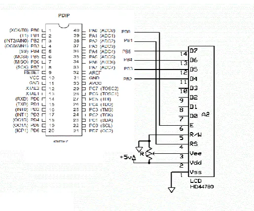
D. Pin Configuration
:
Figure 11. Pin configuration of Atmega16microcontroller interface with LCD
ATmega16 Microcontroller Features
:
The AVR ATmega16 provides the following features: It has low power CMOS 8-bit controller with AVR RISC
Its throughput is up to 16MIPS per
It has 32 General purpose registers directly connected to 16 Kbytes In-System programmable flash
512 bytes of EEPROM, 1k byte SRAM, JTAG
Three timer/counter for comparison
Internal and external interrupts
Serial programmable USART+I2C protocol
3
.
RESULTS
Load P.F (Before
APFC Circuit)
P.F (After APFC Circuit)
LOAD 0.66 0.97
Sr. No. APFC LOAD CAPACITOR P.F
1. Without
R-L
None 0.672. With
R-L
1 0.783. With
R-L
1&2 0.874. With
R-L
1,2&3 0.97Before insertion of APFC circuit Power factor of at load condition is observed as 0.66, while after insertion of APFC circuit power factor gets improve to 0.97.
4.CONCLUSIONS
This paper deals with advancement method of power factor improvement by using microcontroller. As Switching of capacitors are done automatically, more correct results are obtained. Power factor correction technique makes system steady and due to improvement in power factor, its efficiency also increases. The automatic power factor improvement using capacitive load banks is very efficient as it reduces the cost by decreasing the power drawn from the supply. As it operates automatically, manpower is not required and this Automatic Power factor improvement using capacitive load banks can be used for the industries purpose in the future.
5.REFERENCES
[1] “The 8051 Microcontroller and Embedded Systems” by Muhammad Ali Mazidi and Janice Gillis pie Mazidi.
[2] Institute of Electrical and Electronics Engineers. The authoritative dictionary of IEEE standards terms. Standards Information Network, Std. 100, IEEE Press, 2000.
[image:4.595.38.296.313.527.2]© 2017, IRJET | Impact Factor value: 5.181 | ISO 9001:2008 Certified Journal | Page 1813 [4] J.G. Cho, J.W. Won, H.S. Lee , “Reduced conduction loss
zero-voltage-transition power factor correction converter with low cost, ”IEEE Trans. Industrial
Electron.vol.45,no3,Jun. 2000,pp395-400.
[5] Jiang, Y. et al, A Novel Single-phase Power Factor Correction Scheme, Applied Power Electronics Conference and Exposition, 1993, pp. 287-292.
[6] Zero Crossing Detector, Available at: http://www.ustudy.in/node/4699, Accessed on: February 4, 2015.