© 2018, IRJET | Impact Factor value: 6.171 | ISO 9001:2008 Certified Journal | Page 2799
EVALUATION OF EXISTING BUILDING FOR PERFORMANCE CHECK IF
ANOTHER FLOOR IS PROPOSED FOR CONSTRUCTION
1
Doredla Nagaraju,
2G.Sai,
3K.Akhil,
4S.Srikanth,
5T.Prasad,
6K.Rama Koteswara Rao
1 Assistant Professor, Department Of Civil Engineering, Narasaraopeta Engineering College, Narasaraopet, India 2, 3,4,5,6 B.Tech, Students, Department Of Civil Engineering, Narasaraopeta Engineering College, Narasaraopet, India
---***---Abstract
- Existing buildings especially aging ones arecurrently in urgent need for upgrading to improve their performance and potentially achieve performance certification. Building owners often need to identify and implement building upgrades that maximizes the sustainability of their buildings for seismic resistivity. This paper presents the development of an optimization model that maximizes the performance for existing G+4building within specified upgrade budget to G+5building. Structural elements are used in structural analysis to split a complex structure into simple elements. The present model is expected to support decisions makers, building owners and operators, building managers, and contractors to optimize the use of their upgrade budgets and maximize the performance of their buildings.
Key Words: Storey, Loads, Beams, Columns, yield strength,
Compressive strength, Deflection, Structure, Stress, moments, STAAD PRO.
I.INTRODUCTION
In late 2005, Research Engineers International was bought by Bentley Systems. The commercial version, STAAD PRO, is one of the most widely used structural analysis and design software products worldwide. It supports several steel, concrete and timber design codes.Version-v8i (SELECT series-5). STAAD PRO is used to analyse the Super Structural elements like beams, Columns, Footings, Trusses, etc., as it is used to reduce the manual calculation and reduces the time.
A column or pillar in architecture and structural engineering is a structural element that transmits, through compression, the weight of the structure above to other structural elements below. In other words, a column is a compression member.
A beam is a structural element that primarily resists loads applied laterally to the beam’s axis. Its mode of deflection is primarily by bending. The loads applied to the beam result in reaction forces at the beam’s support points. The total effect of all the forces acting on the beam is to produce shear forces and bending moments within the beam, that in turn induce internal stresses, strains and deflections of the beam.
II. OBJECTIVES FOR THE STUDY
Following are some objectives of this Project work. 1. To design an extra storey on already existing structure by using STAAD PRO.
2. Whether it is in safe condition (or) unsafe condition for construction.
3. To check whether the existing structure is suitable for withstanding earthquake forces.
4. To design an extra storey on the existing structure withstanding the earthquake and wind forces.
5. To check the design whether it can withstand the combined earthquake and wind forces.
6. To design an optimal section with slight changes in the sectional dimensions.
7. To make the structure as a under reinforced section instead of designing as an over reinforced section.
III. RESEARCH METHODOLOGY
Inputting the job Information: Generating the 3D model geometry:
There are two methods of creating a structure data in STAAD PRO.
a. Using the command file also called “The STAAD PRO Editor method”.
b. Using the graphical user interface (GUI).
© 2018, IRJET | Impact Factor value: 6.171 | ISO 9001:2008 Certified Journal | Page 2800 Fig 1 The model of structure with all the beams
Assigning the material:
[image:2.595.325.555.166.363.2]As after creating the beams and columns we will assign material to them as we require. Our design is concrete design hence we have assigned the concrete material to the beams and columns as shown in fig 2.
Fig 2 3D Rendered model
Specifying member properties:
The properties of the beams and columns is their size(width, depth of cross-section).So with the help of this command we have inputted the different properties (as circular, rectangular, square) and assign these properties to specified members as shown in fig 3.
Fig 3 Figure showing its Assigned Properties and Orientation
Specifying material constants:
[image:2.595.43.274.326.477.2]As we assigned the concrete material so by default we have the constants of concrete and we don’t need to use this command separately. Or if we need to change the constants we can do so by this command as shown in fig 4.
Fig 4 Figure showing its material constants assigned
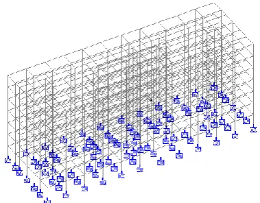
Specifying Supports:
The supports are first created (as we created fixed supports) and then these are assigned to all the lowermost nodes of structure where we are going to design the foundation as shown in fig 5.
Fig 5 The model with the fixed supports.
Specifying Loads:
This is done in following two steps:
a. Firstly creating all the load cases according to IS 456:2000 & IS 1893:2002.
[image:2.595.343.533.473.621.2] [image:2.595.39.288.573.745.2]© 2018, IRJET | Impact Factor value: 6.171 | ISO 9001:2008 Certified Journal | Page 2801 IS Codes considered for the Design:-
IS RCC CODE 456-2000
IS CODE OF DESIGN STRENGTH 1566 IS CODE OF HYSD 1786-1985
The STAAD PRO program can produce all types of loads and can assign them to the structure. It also has the capability to apply the dead load on the structure. There are some definitions of loads which are firstly created according to IS codes before creating specific load cases (As Seismic or wind load). Here below are some types of loads as we have assigned.
[image:3.595.317.557.45.243.2]Dead Load: The load coming on framed structure due to self-weight of beams, columns, slabs or walls. This load will act as uniformly distributed load over the supporting beams as shown in fig 6.
Fig 6 The dead load coming on beams
Live Load: The live load comes on structure due to extra necessary things in the house. There will be different Live Loads acting in the structure due to different uses of building. As here we have used various types of different live loads in our structure.
Dimensions & Loads Considered (fig 7 & fig 8):-
For Existed Building
Provided Column Size - 600 X 230 MM, 400 X 230 MM, 350 X 230 MM, 450 X 230 MM
Provided Beam Size - 450 X 230 MM Steel Provided - HYSD Bars and
For beams - 8 bars of 10MM dia with 2 legged stirrups of 8MM dia
For columns - 25 bars of 8MM dia bars with 2 legged stirrups of 8MM dia
Beam - 265 to 1272
Column - 1 to 96 ,1605 to 1642 ,1647 to 1742 ,1747 to 1842 ,1847 to 1942 ,1947 to 2042 ,2047 to 2104
[image:3.595.58.264.306.449.2]Mix grade of concrete - M30
Fig 7 Figure showing its Specifying the Properties to the Assigned beams
Loads Assigned
Dead Load - -12 KN/M (for External walls) Dead Load - -6 KN/M (for Internal walls) Dead Load - -3 KN/M (for Open terrace walls) Dead Load - -31 KN/M (for Steps Rising beam) Dead Load - -16 KN/M (for Mid landing beam) Live Load - -2 KN/M
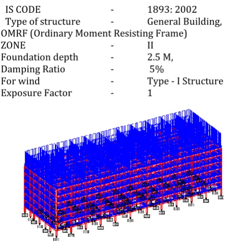
Considered load definition (EQ & WIND) for redesign of the existing structure for wind & seismic resistivity:-
EQ & Wind Parameters considered for design:-
IS CODE - 1893: 2002
Type of structure - General Building, OMRF (Ordinary Moment Resisting Frame)
ZONE - II
Foundation depth - 2.5 M,
Damping Ratio - 5%
For wind - Type - I Structure
Exposure Factor - 1
Fig 8 The Live load coming on beams Load Combinations:
[image:3.595.315.557.451.696.2]© 2018, IRJET | Impact Factor value: 6.171 | ISO 9001:2008 Certified Journal | Page 2802 Indian code we can generate loads according to that and
then adding these loads. These combinations do not require to be assigned on members.
Hence all the loads are assigned on the structure we will move towards forward step.
Specifying the analysis type:
Before doing the analysis for the loads we require specifying analysis command which we need is linear static type. Choosing statics check, we will add this command.
Post-Analysis print command:
As we require obtaining member end forces and support reactions written in the output file. By clicking on post-analysis a dialog box will open then by clicking define command, we can add the commands which we need and can assign them to members for which these will be analyzed.
Run Analysis:
` The structure will be analyzed to the loads and this command will also show if there is any warning or error.
Post-Processing mode:
`We can see results in this mode. The deflection, bending moment, shear forces and reactions on supports can been on the structure with values. The figures shown below are under Dead Load. We can also see figures under Live Load or other which we want.
After doing all the structural analysis of our structure, we have designed it to find out the steel used for the reinforcement for the columns and beams.
By selecting the code IS: 456 2000 for the concrete design we will then define parameters for our design as:
[image:4.595.44.270.635.745.2]After giving all these inputs we will now give commands as for the design of beams and columns. These are selected once added and then assigned to the structure to appropriate components. Then the structure is again analyzed for the generation of report.
Fig 9 The Stresses on each beam and column.
IV. CONCLUSIONS
The IS code methods describing some sufficient guidelines about applying an extra floor on existing building. Software like STAAD PRO is used as a tool for analyzing and gives the results on designing details. To compare to manual calculations then the software should be gives on accurate results and it should be taken less time. Software shows the maximum deflection values and shear force and bending moments and reinforcement details.
The demonstrated capabilities of the present model can assist decisions makers, building owners and operators, building managers, and contractors who wish to improve building performance. Due to this difference in reaction load the above mentioned columns are failing for the reinforcement design as the section is undergoing for over reinforced section followed under IS 456:2000.hence the above columns section should be redesigned or should undergo for lateral supports or retrofitting of the structure for the failed column sections. So we should be increase the cross sectional area of failure columns by using Re jacketing process as a Redesign process. After increasing the cross sectional area then it should be shows the results on safe condition. The results had been done by the using of STAAD PRO software.
The results of the optimization model showed its capabilities to
(1) Identify replacements for building components of beams and columns including their detailed location at the building.
(2) Identify selected credit area alternatives that need to be implemented in the building.
(3) Model and calculate stability of buildings using STAAD PRO.
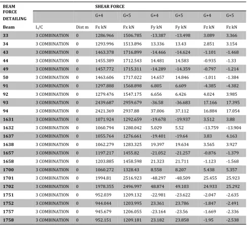
© 2018, IRJET | Impact Factor value: 6.171 | ISO 9001:2008 Certified Journal | Page 2803 4. RESULTS & DISCUSSION
The following below tables(1&2) shows the comparison of shear forces and bending moments for the Existing Column and Beam sizes with the general gravity load combination(3.Dead Load + Live Load) applied for the structure:-
Differences b/w G+4 & G+5:
BEAM FORCE DETAILING
SHEAR FORCE
G+4 G+5 G+4 G+5 G+4 G+5
Beam L/C Dist m Fx kN Fx kN Fy kN Fy kN Fz kN Fz kN
33 3 COMBINATION 0 1286.966 1506.785 -13.387 -13.498 3.089 3.366
34 3 COMBINATION 0 1293.996 1513.896 13.336 13.43 2.851 3.154
43 3 COMBINATION 0 1463.378 1716.899 -14.466 -14.624 -1.101 -1.468
44 3 COMBINATION 0 1455.389 1712.543 14.481 14.583 -0.935 -1.33
49 3 COMBINATION 0 1457.772 1715.311 -14.289 -14.359 -0.797 -1.214
50 3 COMBINATION 0 1463.606 1717.022 14.657 14.846 -1.011 -1.384
91 3 COMBINATION 0 1297.888 1568.898 6.805 6.609 -4.385 -4.382
92 3 COMBINATION 0 1279.476 1547.175 6.656 6.426 4.024 3.985
93 3 COMBINATION 0 2439.687 2959.679 -36.58 -36.683 17.166 17.395
94 3 COMBINATION 0 2421.369 2937.88 37.006 37.112 16.884 17.054
1631 3 COMBINATION 0 1071.924 1292.659 -19.678 -19.937 3.512 3.88
1632 3 COMBINATION 0 1060.794 1280.042 5.029 5.52 -13.759 -13.904
1637 3 COMBINATION 0 1055.764 1276.661 -19.401 -19.64 3.83 4.163
1638 3 COMBINATION 0 1062.279 1283.325 19.397 19.634 3.565 3.927
1657 3 COMBINATION 0 1197.217 1455.82 -21.052 -21.257 -0.876 -1.379
1658 3 COMBINATION 0 1203.885 1458.598 21.323 21.711 -1.123 -1.568
1700 3 COMBINATION 0 1060.272 1328.43 8.558 8.207 5.438 5.357
1701 3 COMBINATION 0 1994.81 2516.923 -48.297 -48.509 25.455 25.923
1702 3 COMBINATION 0 1978.355 2496.997 48.874 49.103 24.933 25.292
1751 3 COMBINATION 0 952.039 1209.132 -22.981 -23.622 -2.047 -2.635
1752 3 COMBINATION 0 944.044 1203.995 23.361 23.786 -1.847 -2.491
1757 3 COMBINATION 0 945.679 1206.055 -23.164 -23.56 -1.669 -2.336
[image:5.595.55.542.160.608.2]1758 3 COMBINATION 0 952.151 1209.181 23.182 23.858 -1.95 -2.538
Table 1
BEAM FORCE DETAILING
BENDING MOMENT
G+4 G+5 G+4 G+5 G+4 G+5
Beam L/C Dist m Mx kNm Mx kNm My kNm My kNm Mz kNm Mz kNm
33 3 COMBINATION 0 -0.04 -0.062 -3.227 -3.575 -10.942 -11.039
34 3 COMBINATION 0 0.084 0.104 -2.909 -3.293 10.93 11.001
43 3 COMBINATION 0 0.087 0.119 1.371 1.828 -11.831 -11.959
44 3 COMBINATION 0 -0.105 -0.136 1.145 1.635 11.867 11.954
© 2018, IRJET | Impact Factor value: 6.171 | ISO 9001:2008 Certified Journal | Page 2804
50 3 COMBINATION 0 -0.076 -0.107 1.249 1.712 12.092 12.264
91 3 COMBINATION 0 0.047 0.058 3.642 3.642 5.727 5.5
92 3 COMBINATION 0 -0.055 -0.065 -3.281 -3.246 5.619 5.358
93 3 COMBINATION 0 -0.069 -0.078 -14.645 -14.829 -28.392 -28.476
94 3 COMBINATION 0 0.021 0.022 -14.475 -14.598 29.291 29.381
1631 3 COMBINATION 0 -0.03 -0.061 -4.719 -5.258 -29.129 -29.465
1632 3 COMBINATION 0 0.001 0.036 20.325 20.512 6.709 7.432
1637 3 COMBINATION 0 0.004 -0.03 -5.216 -5.699 -28.698 -29.009
1638 3 COMBINATION 0 0.039 0.069 -4.813 -5.342 28.747 29.052
1657 3 COMBINATION 0 0.062 0.102 0.811 1.531 -31.064 -31.324
1658 3 COMBINATION 0 0.002 -0.043 1.18 1.816 31.506 32.013
1700 3 COMBINATION 0 -0.049 -0.055 -8.26 -8.154 13.525 13.047
1701 3 COMBINATION 0 -0.027 -0.034 -37.419 -38.008 -73.484 -73.747
1702 3 COMBINATION 0 0 -0.001 -36.722 -37.163 74.56 74.862
1751 3 COMBINATION 0 -0.094 -0.046 2.669 3.518 -33.946 -34.83
1752 3 COMBINATION 0 0.064 0.02 2.377 3.309 34.495 35.085
1757 3 COMBINATION 0 -0.045 -0.004 2.105 3.071 -34.206 -34.752
[image:6.595.30.568.448.758.2]1758 3 COMBINATION 0 0.106 0.057 2.524 3.373 34.241 35.177
Table 2
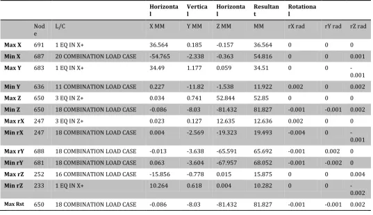
After considering the Earthquake Loads & Wind Loads and a Combination of Earthquake & Wind Load nodal displacements and beam displacements are obtained as the tables(3&4) specified below for G+4:-
Horizonta
l Vertical Horizontal Resultant Rotational
Nod
e L/C X MM Y MM Z MM MM rX rad rY rad rZ rad
Max X 691 1 EQ IN X+ 36.564 0.185 -0.157 36.564 0 0 0
Min X 687 20 COMBINATION LOAD CASE -54.765 -2.338 -0.363 54.816 0 0 0.001
Max Y 683 1 EQ IN X+ 34.49 1.177 0.059 34.51 0 0
-0.001
Min Y 636 11 COMBINATION LOAD CASE 0.227 -11.82 -1.538 11.922 0.002 0 0.002
Max Z 650 3 EQ IN Z+ 0.034 0.741 52.844 52.85 0 0 0
Min Z 650 18 COMBINATION LOAD CASE -0.086 -8.03 -81.432 81.827 -0.001 -0.001 0.002
Max rX 247 3 EQ IN Z+ 0.023 0.127 12.635 12.636 0.002 0 0
Min rX 247 18 COMBINATION LOAD CASE 0.004 -2.569 -19.323 19.493 -0.004 0
-0.001
Max rY 688 18 COMBINATION LOAD CASE -0.013 -3.638 -65.591 65.692 -0.001 0.002 0
Min rY 681 18 COMBINATION LOAD CASE 0.063 -3.604 -67.957 68.052 -0.001 -0.002 0
Max rZ 252 16 COMBINATION LOAD CASE -15.856 -0.778 0.015 15.875 0 0 0.004
Min rZ 233 1 EQ IN X+ 10.264 0.618 0.004 10.282 0 0
-0.002 Max Rst 650 18 COMBINATION LOAD CASE -0.086 -8.03 -81.432 81.827 -0.001 -0.001 0.002
© 2018, IRJET | Impact Factor value: 6.171 | ISO 9001:2008 Certified Journal | Page 2805
Beam L/C Node Fx kN Fy kN Fz kN Mx kNm My kNm Mz
kNm
Max Fx 93 11 COMBINATION LOAD CASE 185 2439.687 -36.58 17.166 -0.069 -14.645 -28.392
Min Fx 18 3 EQ IN Z+ 35 -322.132 -112.66 -0.084 -0.17 0.07 -206.98
Max Fy 764 16 COMBINATION LOAD CASE 293 0.235 228.351 0.602 0.621 -1.926 318.975
Min Fy 767 11 COMBINATION LOAD CASE 594 -24.902 -210.772 0.11 0.159 0.378 230.429
Max Fz 1801 18 COMBINATION LOAD CASE 293 1140.175 -48.755 90.065 0.195 -134.185 -72.616
Min Fz 1670 3 EQ IN Z+ 124 -9.654 -0.197 -49.7 0.108 75.295 -0.277
Max Mx 830 16 COMBINATION LOAD CASE 294 -3.113 90.601 -3.958 36.784 2.134 67.353
Min Mx 801 18 COMBINATION LOAD CASE 392 -4.167 69.513 -1.433 -20.966 0.966 45.167
Max My 1801 18 COMBINATION LOAD CASE 393 1125.513 -48.755 90.065 0.195 135.942 73.613
Min My 1801 18 COMBINATION LOAD CASE 293 1140.175 -48.755 90.065 0.195 -134.185 -72.616
Max Mz 20 22 COMBINATION LOAD CASE 39 1113.409 172.33 -0.043 -0.45 0.04 324.947
[image:7.595.27.570.69.309.2]Min Mz 93 16 COMBINATION LOAD CASE 185 2130.513 -144.455 15.353 0.512 -12.92 -254.98
Table 4
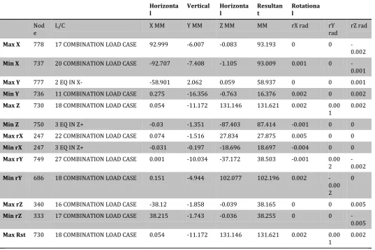
After considering the Earthquake Loads & Wind Loads and a Combination of Earthquake & Wind Load nodal displacements and beam displacements are obtained as the tables(5&6) & fig 10 specified below for G+5:-
Horizonta
l Vertical Horizontal Resultant Rotational
Nod
e L/C X MM Y MM Z MM MM rX rad rY rad rZ rad
Max X 778 17 COMBINATION LOAD CASE 92.999 -6.007 -0.083 93.193 0 0
-0.002
Min X 737 20 COMBINATION LOAD CASE -92.707 -7.408 -1.105 93.009 0.001 0
-0.001
Max Y 777 2 EQ IN X- -58.901 2.062 0.059 58.937 0 0 0.001
Min Y 736 11 COMBINATION LOAD CASE 0.275 -16.356 -0.763 16.376 0.002 0 0.002
Max Z 730 18 COMBINATION LOAD CASE 0.054 -11.172 131.146 131.621 0.002 0.00
1 0.002
Min Z 750 3 EQ IN Z+ -0.03 -1.351 -87.403 87.414 -0.001 0 0
Max rX 247 22 COMBINATION LOAD CASE 0.074 -1.516 27.834 27.875 0.005 0 0
Min rX 247 3 EQ IN Z+ -0.031 -0.197 -18.696 18.697 -0.004 0 0
Max rY 749 27 COMBINATION LOAD CASE 0.001 -10.034 -37.172 38.503 -0.001 0.00
2 -0.002
Min rY 686 18 COMBINATION LOAD CASE 0.151 -4.944 102.077 102.196 0.002
-0.00 2
0
Max rZ 340 16 COMBINATION LOAD CASE -38.12 -1.858 -0.039 38.165 0 0 0.005
Min rZ 333 17 COMBINATION LOAD CASE 38.215 -1.743 -0.036 38.255 0 0
-0.005
Max Rst 730 18 COMBINATION LOAD CASE 0.054 -11.172 131.146 131.621 0.002 0.00
1 0.002
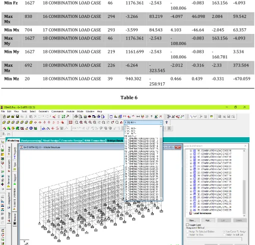
[image:7.595.32.570.378.736.2]© 2018, IRJET | Impact Factor value: 6.171 | ISO 9001:2008 Certified Journal | Page 2806
Beam L/C Node Fx kN Fy kN Fz kN Mx
kNm My kNm Mz kNm
Max Fx 93 18 COMBINATION LOAD CASE 185 3176.557 -37.223 -65.621 -0.431 92.724 -29.433
Min Fx 93 3 EQ IN Z+ 185 -421.434 0.126 53.456 0.239 -70.099 0.419
Max Fy 768 16 COMBINATION LOAD CASE 693 -31.337 250.171 3.603 1.005 -11.654 326.994
Min Fy 692 18 COMBINATION LOAD CASE 226 -6.264
-323.545 -2.012 -0.316 -2.33 373.504
Max Fz 1755 16 COMBINATION LOAD CASE 247 1149.755 -20.095 70.529 -0.568
-106.099 -29.903
Min Fz 1627 18 COMBINATION LOAD CASE 46 1176.361 -2.543
-108.006 -0.083 163.156 -4.093
Max
Mx 830 16 COMBINATION LOAD CASE 294 -3.266 83.219 -4.097 46.098 2.084 59.542
Min Mx 704 17 COMBINATION LOAD CASE 293 -3.599 84.543 4.103 -46.64 -2.045 63.357
Max
My 1627 18 COMBINATION LOAD CASE 46 1176.361 -2.543 -108.006 -0.083 163.156 -4.093
Min My 1627 18 COMBINATION LOAD CASE 219 1161.699 -2.543
-108.006 -0.083 -160.781 3.534
Max
Mz 692 18 COMBINATION LOAD CASE 226 -6.264 -323.545 -2.012 -0.316 -2.33 373.504
Min Mz 20 18 COMBINATION LOAD CASE 39 940.302
[image:8.595.42.556.67.420.2]-258.917 0.466 0.439 -0.331 -470.059
Table 6
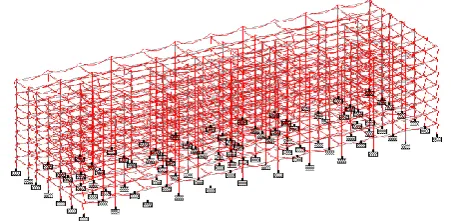
[image:8.595.41.553.217.708.2]© 2018, IRJET | Impact Factor value: 6.171 | ISO 9001:2008 Certified Journal | Page 2807 From the results shown in fig 11 obtained from the applied loads& load combinations the failed beams and columns displacements ,reaction loads, shear force and bending moments are considered .A redesign of the existing structural properties have been proposed to sustain the loads.
Fig 11 Results obtained after applying load combinations for G+5
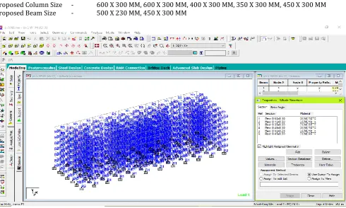
For redesign of the existing structure (fig 12), the following sectional properties have been modified:-
Proposed Column Size - 600 X 300 MM, 600 X 300 MM, 400 X 300 MM, 350 X 300 MM, 450 X 300 MM Proposed Beam Size - 500 X 230 MM, 450 X 300 MM
[image:9.595.43.534.434.728.2]© 2018, IRJET | Impact Factor value: 6.171 | ISO 9001:2008 Certified Journal | Page 2808 REFERENCES
[1] Design and Practical Limitations in Earthquake Resistant Structures and Feedback. INTERNATIONAL JOURNAL OF CIVIL ENGINEERING AND CIVIL ENGINEERING (IJCIET), Volume 5, Issue 6, June (2014), pp. 89-93
[2] Comparison of design results of a Structure designed using STAAD PRO and ETABS Software, INTERNATIONAL JOURNAL OF CIVIL AND STRUCTURAL ENGINEERING, Volume 2, No 3, 2012
[3] Analysis of multi storey building with precast load bearing walls. INTERNATIONAL JOURNAL OF CIVIL AND STRUCTURAL ENGINEERING, Volume 4, No 2, 2013
[4] Analysis and Design of shopping mall against lateral forces. INTERNATIONAL JOURNAL OF ENGINEERING SCIENCE INVENTION, Volume 3 Issue 4 April 2014.
[5] Lateral Load Analysis of Shear Wall and Concrete Braced Multi-Storeyed R.C Frame with the Effect of Ground Soft Storey. INTERNATIONAL JOURNAL OF APPLIED SCIENCES AND ENGINEERING RESEARCH, Vol. 2, Issue 09, 2014.
[6] Behaviour of multistoried building under the effect of wind load. INTERNATIONAL JOURNAL OF APPLIED SCIENCES AND ENGINEERING RESEARCH, Vol. 1, Issue 4, 2012.
BIOGRAPHIES
DOREDLA NAGARAJU M.Tech [SE] ,MBA ,MISTE, AMIE ,Jr.AM.ASCE, Assistant Professor, Department of Civil Engineering, Narasaraopeta Engineering College [Autonomous], Narasaraopet, Andhra Pradesh,India.
GRANDHI SAI KUMAR
B.Tech, Department of Civil Engineering, Narasaraopeta Engineering College [Autonomous], Narasaraopet, Andhra.
KOTHAMASU AKHIL
B.Tech, Department of Civil Engineering, Narasaraopeta Engineering College [Autonomous], Narasaraopet, Andhra Pradesh, India.
SIRIKONDA SRIKANTH
B.Tech, Department of Civil Engineering, Narasaraopeta Engineering College [Autonomous], Narasaraopet, Andhra Pradesh, India.
TANGIRALA PRASAD
B.Tech, Department of Civil Engineering, Narasaraopeta Engineering College [Autonomous], Narasaraopet, Andhra Pradesh, India.