Secure and Scalable Data Collection with Time
Minimization in the Smart Grid
Suleyman Uludag
1, King-Shan Lui
2, Wenyu Ren
3, and Klara Nahrstedt
31
Department of Computer Science, University of Michigan - Flint, MI, USA
2
Department of Electrical and Electronic Engineering, The University of Hong Kong, Hong Kong
3Department of Computer Science, University of Illinois at Urbana-Champaign, IL, USA
Abstract—Deployment of data generation devices, such as sensors and smart meters, has been accelerating towards the vision of Smart Grid. The volume of data to be collected increases tremendously. Secure, efficient, and scalable data col-lection becomes a challenging task. In this paper, we present a secure and scalable data communications protocol for Smart Grid data collection. Under a hierarchical architecture, relay nodes (aka data collectors) collect and convey the data securely from measurement devices to the power operator. While the data collectors can verify the integrity, they are not given access to the content, which may pave the way for third party providers to deliver value-added services or even the data collection itself. We further present optimization solutions for minimizing the total data collection time.
I. INTRODUCTION
In the Smart Grid, massive number of sensors or measure-ment devices will be installed to collect real-time information. The generated data should be collected in a secure, efficient, and scalable manner. To make it scalable, a hierarchical data collection framework is usually adopted. For example, in Advanced Metering Infrastructure (AMI), smart meters first report measurements to data concentrators [1]. Thereby, the power operator does not have to maintain a separate, expensive connection with each smart meter. Apart from data collection, this hierarchical communication structure should also allow the power operator to send an instruction to the devices. To maintain fast response, messages, data or instructions, should be delivered efficiently and as fast as possible. The messages should be protected to prevent from information leak and launch of attacks. In this paper, we develop a comprehensive protocol that allows a power operator to collect data, as well as send commands to measurement devices in a secure, scalable, and efficient manner.
PO
DC1
DC2
DC3
DCi
MD1
MD2
MD3
MD4
[image:1.612.118.235.598.698.2]MDj
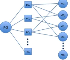
Fig. 1. Hierarchical Data Collection Structure.
Fig. 1 presents the data collection architecture considered
in this paper. The Measurement Devices (MDs) are sensors or smart meters that generate power-grid specific data. They are small telemetric devices and computationally constrained. Each MD is connected to at least one Data Collector (DC), and each DC may connect to multiple MDs. The Power Operator (PO) has a direct connection with each DC. PO and DCs are relatively more powerful than MDs. The data are reported to PO via a set of DCs. PO may also issue commands to the MDs via the DCs. Theoretically, a DC is trustworthy if it is within the security domain of the PO.
However, due to the massive number of MDs and their dispersion over a large area, it may not be appropriate to assume DCs can be completely trusted. In addition, one of the seven actors identified by The National Institute of Standards and Technology (NIST) in the Smart Grid (SG) Framework [2] is third party service providers which are to furnish value-added services. We assume honest-but-curious model for DCs. Thus, the data collection tasks may be outsourced to third party service providers [3]. Besides, the benefits of cloud computing [4] may be accrued for storage and processing of the data collected. Data sharing to others to provide services like energy management services can be facilitated as well.
In some other applications [5], DCs are mobile and the connections between DCs and MDs are dynamic. Therefore, it would be desirable for MDs to encrypt their data in a way that DCs do not have access to them. In other words, each MD should encrypt its data using an appropriate key to keep its data private from DCs and other possible adversaries. On the other hand, due to limitation in memory and computational capability, the encryption algorithm used should be efficient. PO should also protect its commands appropriately. Apart from ensuring the security of these commands, it is also crucial to deliver data and commands promptly because fast actions of MDs are necessary to maintain the stability and health of the smart grid. Because the network delay for different DCs to collect data from a certain MD would be different, to make the data collection more efficient, we also study how to assign DCs to MDs to minimize the time for data collection.
Our contributions in this paper may be summarized as follows:
• Under a hierarchical infrastructure, we have proposed a
• Our secure data collection scheme does not assume
trusted DCs, rather they are considered to be
honest-but-curious entities. This may pave the way for outsourcing
the data collection and third party service providers as envisioned by the NIST’s Smart Grid Framework [2],
• We have coupled the secure date collection with an
opti-mization problem formulation with the objective function of time minimization, which is a first in the literature as a joint security and optimization approach,
• We have shown the NP-Hardness of the problem and
developed an efficient heuristic solution,
• We have also provided a solution to the assignment of
DCs to MDs as part of the optimization framework. The rest of the paper is organized as follows: Sec. II describes existing efforts on data collection in smart grids. We provide the system and protocol overview in Sec. III. The details of the protocol are described in Sec. IV and V. In Sec. VI, we analyze the time performance of our mechanism and present the DC-MD assignment problem as an optimization problem. We conclude our paper in Section VIII.
II. RELATEDWORK
Data integrity and confidentiality of end-to-end data have been studied extensively in the Internet. However, most schemes, such as TLS [6], assume the devices have abun-dant memory and computational power to perform expensive cryptographic operations. In smart grids, on the other hand, reporting devices have limited memory with a slow CPU. Traditional Internet security protocols are thus not suitable for data collection in smart grids [7].
DNP3 (Distributed Network Protocol) [8] is a standard communications protocol used in SCADA (Supervisory Con-trol And Data Acquisition), the data collection subsystem of power grids. It assumes all components are within the security perimeter of the operator and is not designed to protect data forwarded by the DC as in our situation. A more recent standard for substation automation is the IP-based IEC (the International Electrotechnical Commission) 61850 [9]. Yet, IEC 61850 was also initially designed without security mechanisms [10]. It is thus generally agreed by the experts that new security protocols for data collection and command delivery of smart grids need to be developed.
Our proposed approach comprises security aspect of the smart grid data collection as well as the time minimization. In what follows, we provide synopses of related work from these aspects as well as with respect to a variety of other relevant subtopics of our holistic approach.
Collecting data by means of transport layer protocols from a massive number of MDs has been studied in the literature as an option. [11] studies how to reduce the storage needed when the control center needs to establish multiple sessions with the MDs. Long-term shared keys are generated by a function so that the control center only needs to memorize the function but not individual keys. Nevertheless, the key developed this way is not very secure. Besides, the protocol is not suitable for the hierarchical data collection architecture.
Data collection through a data collector is considered in [12]. The authors propose to maintain two separate Transmission Control Protocol (TCP) connections, and the two connections can be protected using different mechanisms independently. Nevertheless, the data collector is assumed to be trustworthy, that is, it can read the data sent by the MD.
Another important aspect of secure data collection is con-cerned with key management. Many assume trusted DC, that is, they do not consider hiding the data from the DCs, such as [13], [14], [15]. Some others assume a direct connection between the PO and MDs [16]–[18] and some others are not suitable for hierarchical data collection as we consider in this paper [16], [17], [19].
The SAKE protocol [20] allows two neighboring sensor nodes to establish keys using hash chains. However, the authors assume the attackers are of limited computational capability as another sensor. The authors in [15] apply the el-liptic curve public key technique to perform key management. Mutual authentication between different entities is studied. Nevertheless, there is no discussion on how to protect the data reported by a sensor.
Some protocols have been developed to establish shared keys when the two parties can establish direct communication. [18] describes how to establish keys and secure unicast and multicast communications. [7] proposes long-term keys to be given to the different parties for protecting messages. [16] describes how to apply the Diffie-Hellman mechanism to establish a shared key for data authentication between two parties. [17], on the other hand, relies on identity-based cryptography. All these mechanisms cannot be applied in the hierarchical data collection model because the PO and the MDs cannot establish a direct connection. The authors in [21] describe how a device establishes shared keys with different controllers at different hierarchical levels. However, it is assumed that a shared key exists between two adjacent controllers. Another approach presented in [22] is based on symmetric cryptography to provide data confidentiality and authentication between sensors and the base station. Again, a master key is assumed with a pre-agreed pseudo-random function in the scheme.
Another category for providing security and privacy [23] ex-ploits the aggregate statistics of the sensed data, such as sum-mation, average, minimum, maximum, etc. These approaches take advantage of in-network data processing (also referred
to as aggregation) to induce some obfuscating operations on
data aggregation schemes without any security schemes, such as [32], [33].
There are also homomorphic encryption-based approaches to hide the collected information from the MDs, such as [34]–[39]. However, homomorphic encryption is a compute-intensive operation.
[40] studies how data generators report data to a
honest-but-curious storage center for a user to retrieve later. To
the best of our knowledge, the data collection trust model assumed in this paper is the most related to our scenario. The storage center is similar to the DC in our model that it is semi-trusted, and data should be hidden from it. MDs in our model are the data generators, while PO is a user in their model. However, the paper suggests to use expensive attribute-based and public key encryption to protect data to incorporate policy consideration. The experimental computational time for a decryption on a message of size less than 1000 bits in a low-end smart meter (TinyPBC library on a 32-bit ARM XScale PXA271 processor) is around 140ms, while the encryption is supposed to be a few times more expensive. Our protocol, on the other hand, encrypts data using the much more light-weighted symmetric key cryptography, which is more suitable for computationally-constrained MDs.
There are some approaches with optimization for the data collection process. Cost minimization of data collection by means of wireless channel selection and transmission schedul-ing has been reported in [41]. A delay minimization of overhead transmission lines over unreliable wireless links is studied in [42]. These and other similar approaches lack any security mechanism as part of their approaches, unlike our proposal in this paper.
An interesting approach in [43] considers the tradeoff be-tween the strength of security and energy consumption jointly for both Phasor Maeasurement Unit (PMU) and AMI data over energy-constrained devices. However, only a generic compar-ison of different cryptographic algorithms over CrossBow and Ember sensor platforms is reported without any attention to the overall data collection scheme.
To the best of our knowledge, no other paper in the literature appears to be proposing a holistic approach for hierarchical data collection with curious-but-honest DCs with a joint goal of minimizing the overall data collection time and assignment of MDs to DCs. Further, we also perform experiments to study the time performance of our mechanism.
III. SYSTEM ANDPROTOCOLOVERVIEW
A. Operations and their requirements
As mentioned in Section I, our communication architecture supports MDs to report data and PO to deliver commands in a timely and secure manner. Table I describes each operation. Op 1 is a regular call-for-data from the PO which is performed periodically. Op 2 is performed when PO detects something abnormal and would like a data report from a particular MD. Time is more critical than a regular data reporting. Op 3 is done when MD detects something abnormal and would like
Operation Security
Requirement
Time Requirement
Op 1 PO initiates
data collection
of all MDs
or a group of MDs
Data reported should be authenticated and should be read only by the PO, not by other MDs or any DC
The total time to col-lect all data should be minimized
Op 2 PO requests
data from a
certain MD
Same as Op 1 The time needed
should be kept
minimal
Op 3 MD initiates
an urgent data report
Same as Op 1 The data should be
delivered to the PO as soon as possible
Op 4 PO issues
an urgent
command to a group of MDs
The command should be authenticated ap-propriately
Time for each MD to receive and read the command should be minimized
TABLE I
SYSTEMOPERATIONS ANDTHEIRREQUIREMENTS.
to report to the PO. OP 4 is issued when PO needs a group of MDs to perform a certain action as soon as possible.
We develop our protocol to be secure from outsider attacks such as eavesdropping, impersonation, and message tamper-ing, etc. There are three types of insiders in the protocol: PO, DCs, and MDs. They are all given with a corresponding pair of public and private key pair (see Section III-B). Similar to other secure communication protocols, we basically assume a signature, which is created by the private key, can be an identity authenticator. That is, if somebody can prove that she has the knowledge of Alice’s private key, we assume this person is Alice. If the working environment is very insecure that even private keys could be stolen easily, our protocol does not work. The system, in this case, probably require another form of authentication such as token-based, bio-metric, instead of key-based.
We assume the PO (the entity that possesses the private key of the PO) is always trustworthy because it is the control of the whole system and it decides how to use the data collected. The
DCs, on the other hand, arehonest-but-curiousthat they would
follow the protocol as specified but would like to read the data and share with others if they could. That is, they would not impersonate another entity in the system, nor actively tamper the data, but would like to learn as much as possible based on the information they can access according to the normal operation of the protocol. As the MDs are devices located in the field (for example, on power grid poles), it is not likely they are under the same physically secure environment as the PO. The chance that leaking private keys is higher. When an attacker gets the private key of a certain MD, it can report fake data to the PO on behalf of the MD. The PO can analyze the data reported to detect whether they were legitimate data or not. Even though this attacker can report fake data on behalf of its victim, it cannot impersonate other entities (other MDs, PO, or DCs) and read the data sent by other MDs.
B. System Parameters
are installed in the field.
1) Long-term keys: We assume there is a key server that
can generate a set of public and private keys for each entity in the system. The public/private key pair is configured into a DC or MD before it is installed in the field. PO, on the other hand, apart from keeping its own key pair, it also remembers the public keys of all MDs and DCs in the system. We
denote the public key and private key of node A as A+ and
A−, respectively. Under normal circumstances, PO would not
publish the public keys of DCs and MDs to the general public. However, our protocol is secure even if the attackers know the public key information of any DC or MD they want to attack.
2) Diffie-Hellman (DH) parameters: We adopt the
Diffie-Hellman key exchange mechanism to develop shared keys between two parties. Due to space limitation, we refer readers to [44] for the details. Generally speaking, DH allows the two parties to develop a secret shared key even eavesdroppers can read the half keys they exchange with each other. Through forgetting half keys and shared keys appropriately, DH keys
also support perfect forward secrecy.
C. Cryptographic functions
To provide authentication, confidentiality, integrity, and other security protections, messages have to be encrypted, hashed, or signed. We assume the PO selects appropriate cryptographic algorithms for the purposes, and these functions are installed in the DCs and MDs. For example, PO may use the Advanced Encryption Standard (AES) for symmetric key encryption and SHA-256 (the Secure Hash Algorithm with 256 bits of key length) for hash computation. Table II summarizes the functions used in the protocol. In the table, PKE is Public Key Encryption, PKD is Public Key Decryption, SKE is Symmetric Key Encryption, SKD is Symmetric Key
Decryption, SIGV is signature verification,Kpis a public key
while Ks is a shared key.
Name Description Name Description
PKE(Kp,M) encryptMusingKp PKD(Kp,C) decryptCusingKp
SKE(Ks,M) encryptMusingKs SKD(Ks,C) decryptCusingKs
[image:4.612.313.562.53.131.2]SIGN(A,M) sign ofMbyA SIGV(A,M) verifyMsigned byA
TABLE II
SYSTEMFUNCTIONS.
Some cryptographic functions run much slower than others. As some smart grid operations are time sensitive, it is very crucial to identify efficient cryptographic functions appropri-ately to protect the communication. To further understand the computational time of the cryptographic functions on computationally constrained devices, we measure the time needed to execute some representative cryptographic functions on Raspberry Pi. Raspberry Pi is a tiny computer with a size similar to a credit card. The CPU is 700MHz and the memory available is 512MB. Due to space limitation, we only present some of the results. More details can be found in [45].
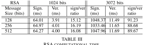
Table III presents the time needed to create an RSA (the Rivest-Shamir-Adleman cryptosystem) signature and verify an RSA signature using different key sizes. The time spent on encrypting a message using public key is similar to the time
RSA 1024 bits 3072 bits
Message Size (bits)
Sign. (ms)
Ver. (ms)
sign/ver ratio
Sign. (ms)
Ver. (ms)
sign/ver ratio
128 64.01 3.91 15.12 1048.37 11.49 91.23
256 64.97 4.01 16.19 1033.46 11.65 88.68
512 64.27 4.00 16.08 1047.96 11.69 89.67
TABLE III
RSACOMPUTATIONAL TIME.
needed in verifying a signature. The time needed on decrypting a message using private key is similar to the time needed on signature creation. It can be observed that the time needed does
not grow with message size but with key size. Column ratio
in the table gives the time ratio of signature computation
signature verification. The
time spent on a private key operation (signing a message) is much longer than that on a public key operation (verifying a signature). An efficient protocol should not require MDs to sign a lot of messages, especially when a long RSA key is used.
We also measured the time needed to generate different Diffie-Hellman keys with different key sizes [45]. A DH shared key generation is more expensive than an RSA sig-nature verification. It implies that it may not be appropriate to re-generate DH shared key for each data collection instance. By adopting different cryptographic functions and techniques carefully based on their security features and computational complexities, our protocol facilitates efficient and secure data collection.
D. Protocol Overview
To detect replay attacks, we adopt a similar way as the widely used Kerberos protocol (RFC4120) that uses times-tamps. The parties who talk directly should first synchronize their clocks. When a timestamp is included in a message, the receiver should check whether the carried timestamp is within a certain amount of difference from its local clock. The default threshold in Kerberos is 300 seconds. In our protocol, the threshold would depend on the expected delay in transmitting the message and granularity of clock synchronization.
Because encrypting data using public key cryptography is very expensive, before any data collection, we should first develop shared keys among PO, DCs, and MDs for data protection. To ensure data reported by a certain MD can be decrypted by the PO only, we need to establish a key that is known by PO and that MD. We call a key that is known
by exactly two parties a pairwise shared key. PO and each
DC should also develop a pairwise shared key to protect their conversations. The same applies to DC with each MD it will talk to. Apart from pairwise keys, to facilitate a certain command or instruction to be delivered to a group of MDs in
a secure and efficient manner, we also develop a set ofgroup
keysthat each group key is shared between the PO, a DC, and
the MDs that connect to that DC.
The PO initiates the Shared Key Generation Process to
keys using the long-term public keys to avoid the man-in-the-middle attack. Once the pairwise shared keys and group keys are established, they will be used for data collection and command delivery.
As DH operations are expensive, we should not re-generate the DH shared keys for every data collection. However, it may not be very secure if we use the same shared keys to encrypt data collected at different times. To strike a balance of computational complexity and security, the data encryption key for each data collection instance depends on both the DH shared key and the timestamp. As the timestamp changes for every data collection instance, the data encryption key will be changed even though we do not re-generate the DH shared key. In the following, we will first describe the Shared Key Generation process in Section IV. The detailed message exchanges of the four operations mentioned in Section III-A will be provided in Section V.
IV. SHAREDKEYGENERATION
Let the set of MDs beMDand the set of DCs beDC. Before
the PO initiates the process, PO has to assign a set of MDs
for DC to connect to. We let MDLISTi⊆MD be the set of
MDs that are assigned toDCi. Definitely,∪DCi∈DCMDLISTi=
MD. However, MDLISTi∩MDLISTj, where i6= j, may not
necessarily be /0. It is possible that PO would like multiple DCs to collect data from the same MD to enhance reliability. In fact, different assignments between MDs and DCs would differ in data security, cost, and data collection time. In Section VI, we will formulate the assignment problem to minimize the data collection time.
In the rest of this paper, for the ease of discussion, we use
shared keyto refer topairwise shared key. We further denote
KBA as the shared key between A andB. We refer to the set
{PO,DCi} ∪MDLISTias groupGi, and the group key ofGiis
GKi. We useM1||M2 to represent concatenating messagesM1
and M2. The definitions of the functions used can be found
in Table II.
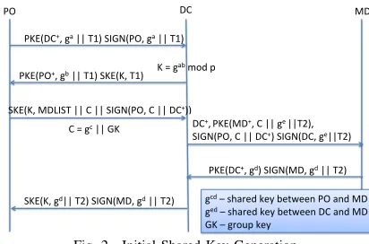
Figure 2 presents a summary of the initial shared key generation process. When the procedure starts, the only keys an MD or a DC knows are its own public/private keys and
the public key of the PO. After the procedure, MDj should
have established KMDPO
j, K
DCi
MDj, and GKi if MDj∈MDLISTi.
Through the procedure, DCi knowsGKi,KDCPOi and K
DCi
MDj for
all MDj∈MDLISTi. The detailed procedure is as follows:
1) PO starts the key generation process. It first generates a
DH secret a to talk to the DCs. PO also captures the current
timestamp T1 and sends the following message to DCi. T1
should be kept until the whole key generation process is done.
PO→DCi: PKE(DCi+,ga||T1),SIGN(PO,ga||T1)
ga is encrypted and so an eavesdropper cannot read ga.
Because PO signs ga||T1 andT1 is a timestamp, an attacker
cannot change T1 or ga easily without being detected.
Sup-pose an attacker also knows DC+i , although he can create
PKE(DCi+,ga0||T10) using his own ga0 and T10, he cannot
forge the signature SIGN(PO,ga||T1). To further enhance
SKE(K, MDLIST || C || SIGN(PO, C || DC+))
PO DC MD
PKE(DC+, ga || T1) SIGN(PO, ga || T1)
PKE(PO+, gb || T1) SKE(K, T1) K = gab mod p
C = gc || GK DC+, PKE(MD+, C || ge ||T2),
SIGN(PO, C || DC+) SIGN(DC, ge||T2)
PKE(DC+, gd) SIGN(MD, gd || T2)
SKE(K, gd|| T2) SIGN(MD, gd || T2) gcd – shared key between PO and MD
ged – shared key between DC and MD
[image:5.612.333.539.47.183.2]GK – group key
Fig. 2. Initial Shared Key Generation.
security, PO can use differenta’s for different DCs, but it has
to generate different signatures for differenta’s and remember
which is used for which DC.
2) When DCi receives the message, it uses DC−i to
re-trieve ga and T1. It checks whether the received signature
SIGN(PO,ga||T1)is correct. If so,DC
i checks whetherT1 is
within an acceptable range. If so, it generates its DH secret
b and computes K as gabmod p. K is then the shared key
between POand DCi (KDCPOi). It encrypts its publich DH key
(gb) using PO’s public key and send it to PO. It also proves
it knowsK by providing SKE(K,T1).
DCi→PO:PKE(PO+,gb||T1),SKE(K,T1)
The timestampT1 is used to detect replay attack as mentioned
in Section III-D. When a message is accepted, DCi should
record T1. When another message arrives that carries a time
stampT, T is accepted only when it is not exactly the same
asT1 and the time difference between T and it local clock is
acceptable. Note that an attacker, who does not know DC−i ,
cannot retrievegaandT1 fromPKE(DCi+,ga||T1). Therefore,
when PO receives a correct reply, he knows that it was DCi
who sent him the message.
3) When PO receives the message, it can retrieve gb using
PO− to compute K. It then uses K to decrypt SKE(K,T1)
and retrievesT1. If this is the same as the one he sent earlier,
PO can confirm that it wasDCiwho sent the message. It then
sends DCi the list of MDs, together with the MDs’ public
keys, that it assignsDCi to talk to. It also createsC for DCi
to talk to the MDs in the list. C contains gc, which is used
for establishing shared keys between PO and MDs, and GKi,
which is the group key of Gi. The public keys of the MDs
should also be sent (We assume they are included inMDLISTi
in Figure 2).
PO→DCi:SKE(K,MDLISTi||C||SIGN(PO,C||DC+i ))where
C=gc||GKi
It is worth noting that PO also sendsSIGN(PO,C||DCi+)and
further encrypts it usingK. This allowsDCi to detect whether
the message has been tampered. AsC is encrypted using K,
it should be safe from eavesdroppers. GKi, which should be
known to PO, DCi, and those MD in MDLISTi, is protected
then.
4) WhenDCireceives the message, it first usesKto retrieve
C and SIGN(PO,C||DC+i ). It verifies whether the signature
for establishing shared keys with the MDs.DCi also captures
the current timestampT2, which must be larger thanT1, and
sends the information to MDj in MDLISTi using the public
keys provided.DCialso needs to send its public key. To allow
MDj to detect whether the message has been tampered, two
signatures, SIGN(PO,C||DC+) and SIGN(DCi,gei||T2), are
sent as well.
DCi→MDj:DC+i ,PKE(MD+j,C||gei||T2),
SIGN(PO,C||DC+),SIGN(DCi,gei||T2)
As DC+i is sent in plaintext and C||gei||T2 is encrypted
using the public key of MDj, it is possible for an
at-tacker to create its own DCi+, PKE(MD+j,C||gei||T2) and
SIGN(DCi,gei||T2). That is, let the attacker beAK. He can
send AK+,PKE(MD+j,C0||gei
ak||T2
0) andSIGN(AK,gei
ak||T2
0)
toMDj, trying to pretend to beDCi. However, he cannot forge
PO to createSIGN(PO,C0||AK+)to cheatMDj. This message
is thus safe from message tampering and an attacker cannot
impersonate DCi.
5) Upon receiving the message, MDj first decrypts
PKE(MD+j,C||gei||T2) using his private key to retrieve
C||gei||T2. It then verifies the two signatures to ensure the
message has not been tampered. It should also check whether
T2 is acceptable in a similar way thatDCiverifiesT1 to detect
replay attacks. If the message passes the tests,MDj creates a
DH secret keydto establish the shared key between itself and
PO (KMDPO
j), which isg
cd, and the shared key withDC
i(KMDDCij),
which is geid. It then encryptsgdusing the public key of DC
i
so that gd is safe from eavesdroppers. It also signsgd andT2
to defend against impersonation and replay attacks.
MDj→DCi:PKE(DCi+,gd),SIGN(MDj,gd||T2)
If an attacker eavesdropped an earlier communication, it cannot simply replay the message from the previous session
because T2 carried in the new message should be different.
By signing gd, we can defend against attackers who want to
impersonate MDj in replying toDCi.
6) When DCi receives the message, it decrypts
PKE(DCi+,gd) using its private key and retrieves gd. It
can then verify the signature to detect whether the message
has been tampered. If not, it sends gd to PO by encrypting
it using K. It also sends the signature by MDj it received to
PO.
DCi→PO: SKE(K,gd||T2),SIGN(MDj,gd||T2)
As only DCi and PO know K, only PO can read gd in
SKE(K,gd||T2). By checking whether T2 is later than T1
kept in memory, PO can detect whether it is a replay. The
signature ofMDj ongdandT2 authenticates that it wasMDj
who created gd.
7) Ifgd||T2 encrypted using K and signed byMDj are the
same, PO can assume the message has not been tampered. PO
can then compute KPO
MDj to beg
cd. Note that as DC
i can only
readgc andgd but neithercnord, it cannot computegcd.gcd
is thus a key shared byPO andMDj only.
We now analyze the memory needed for each entity to keep the shared keys. The PO needs to keep a shared key for each
DC, a shared key for each MD, and a group key for each
group. The total number of keys is 2x|DC| +|MD|.DCi has
to keepKDCPO
i, a shared key with each MD belongs to its group,
and a group key. The total is 2 + |MDLISTi|. For MDj, for
each group Gi it belongs to, it has to keep a shared key with
DCi and the group keyGKi. It is worth noting that MDj can
establish different shared keys with PO through different DCs.
If PO provides differentgc’s for different DCs, the shared keys
developed via different DCs must be different. Even when PO
provides the same gc through different DCs, MD
j can also
establish different shared keys by replying different gd’s for
different DCs. Therefore,MDjhas to keep at most3 x number
of groups it belongs to keys in total. PO decides how many
groups an MD is associated with and can thus establish keys according to the memory available in different MDs.
V. DATACOLLECTION ANDCOMMANDDELIVERY
A. PO initiates Data Collection of a Group of or All MDs
It is a regular data collection initiated by the PO. We want the data collection to be secure, scalable, and efficient. To
ensure data confidentiality and integrity, data reported byMDj
is encrypted using KMDPO
j, a key shared by the PO and MDj
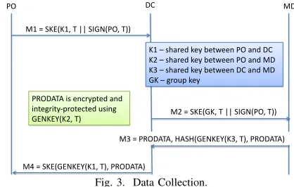
only. Our data collection protocol is scalable because a single DC would collect data from multiple MDs. PO no longer needs to establish a single session to each MD. To acheive efficiency, we do not require computationally-constrained MDs to perform a lot of expensive operations. We also reduce the number of messages exchanged. To further reduce the time of data collection, we study how to assign DCs to collect data from the MDs in Section VI. In the following, we first present the data collection procedure in a step by step manner. Fig. 3
shows the whole process. In the figure, K1, K2, andK3 are
KDCPO
i,K
PO
MDj, andK
DCi
MDj, respectively.
PO DC MD
M1 = SKE(K1, T || SIGN(PO, T))
M2 = SKE(GK, T || SIGN(PO, T))
M3 = PRODATA, HASH(GENKEY(K3, T), PRODATA)
M4 = SKE(GENKEY(K1, T), PRODATA)
K1 – shared key between PO and DC K2 – shared key between PO and MD K3 – shared key between DC and MD GK – group key
[image:6.612.330.539.466.599.2]PRODATA is encrypted and integrity-‐protected using GENKEY(K2, T)
Fig. 3. Data Collection.
1) PO first identifies all the DCs to talk to according to a certain optimization criterion. It captures the current timestamp
T, signs it, encryptsT and the signature usingKDCPO
i, and sends
the encrypted message toDCi. Note that it is possible that PO
does not want to collect data from some MDs inMDLISTi. If
so, PO should also include the list of intended MDs. We omit that in our protocol to simplify the discussion.
PO→DCi: SKE(KDCPOi,T||SIGN(PO,T))
2) Upon receiving the message, DCi can retrieve
the signature to ensure the message has not been tampered. To detect whether the message is a replayed one, it checks whether
T is acceptable. It then encrypts T||SIGN(PO,T)) using the
group keyGKi and sends the message toMDj∈MDLISTi (or
only the MDs PO wants to collect data from).
DCi→MDj:SKE(GKi,T||SIGN(PO,T))
By encrypting the message using the group key, DCi only
needs to create a single message for all MDs in its group. However, the group key cannot authenticate it was PO who requested the data collection because it is a key shared by many entities. We thus need to include a signature of PO to
facilitate authentication. This message should work fine ifDCi
has to collect data from every MD in MDLISTi. However,
when some MDs are not supposed to report data, those are
not reporting can also readT in the message. As T is only a
timestamp and is not a secret, knowingT would not allow MDs
to launch any attack. However, if this is a serious concern,DCi
can send SKE(KDCi
MDj,T||SIGN(PO,T)) to the involved MDs
instead. The disadvantage of this approach is DCi needs to
create a different message for different MD and possibly incurs more delay in the data collection process. As an attacker does
not know GKi and cannot forgeSIGN(PO,T), the message is
safe from impersonation.
3) WhenMDj receives the message, it retrieves the content
using GKi. It first verifies the signature and whether T is
within an acceptable range. If so, MDj generates keys for
protecting the data and allowsDCito perform integrity check.
Let the Message Key (MK) beMK=GENKEY(KMDPO
j,T). An
encryption key and an integrity key developed based on MK
are used to protect the data. The protected data is denoted
as PRODATA. As MK depends on T, different MK’s will
be used for different data collection instances even KMDPO
j is
not changed. MDj also generates DK=GENKEY(KMDDCij,T)
to protect from message tampering. The hash of PRODATA
using DK is computed and sent toDCi.
MDj→DCi:PRODATA,HASH(DK,PRODATA)
Note that as PRODATA is encrypted using a derivative of
KPO
MDj,DCicannot decrypt and read it.PRODATAis thus secure
against honest-but-curious DCs. The hash of PRODATA, on
the other hand, is computed using a derivative of KDCi
MDj. DCi
can thus check whether an attacker has tampered the message before relaying the data back to the PO. As an attacker does
not know KDCi
MDj, he cannot impersonate MDj to sendDCi the
data.
4) When the encrypted data arrives, DCi verifies the hash
to ensure PRODATA was generated by MDj even it cannot
decryptPRODATA. It then forwards PRODATAtoPOby
en-crypting it GENKEY(KPO
DCi,T). Alternatively,DCi can encrypt
all the replies from MDs in a single message. In this case,
only a single symmetric key encryption is needed, butPOmay
receive some data later.
DCi→PO: SKE(GENKEY(KDCPOi,T),PRODATA)
5) Upon receiving the message, PO retrieves PRODATA by
decrypting the message using GENKEY(KDCPO
i,T). It also
de-velopsMK to extract the data fromPRODATA. BecauseKDCPO
i
is a shared secret between PO andDCi, an attacker cannot forge
the message. If the message is tampered, say, a bit is flipped,
PRODATAdecrypted would be scrambled and would not pass
the integrity check using MK. The data sent from MDj are
thus remain confidential and secure.
It can be observed that each MD, each DC, and the PO need to perform one public key operation only no matter how many messages it has to handle. Besides, the signature verification that MDs and DCs have to perform is not very expensive when compared with signature creation. Our protocol is thus very light-weight and scalable.
B. PO requests data from MDj
We list the steps PO can take to request date fromMDj:
1) PO first identifies a certain DCi such that MDj∈Gi.T
is the timestamp. Apart from signing the timestamp,POalso
encrypts the timestamp usingKPO
MDj.
PO→DCi:SKE(KDCPOi,T||SIGN(PO,T)||SKE(K
PO
MDj,T))
2) DCi sends the information to MDj after verifying the
signature onT.
DCi→MDj:SKE(KMDDCij,T||SKE(K
PO
MDj,T))
Steps 3 - 5 are the same as in Section V-A.
Similar mechanism can be used for PO to issue an urgent
command toMDj.MDjshould respond with an
acknowledge-ment instead ofPRODATA.
C. MDj initiates an urgent data report
The following are the steps by MDj to report unsolicited
urgent data:
1) MDj first identifies a certain DCi to relay the message
and records the current timestampT.PRODATAandDK
are generated as in Step 3 in Section V-A.
MDj→DCi:
SKE(KDCi
MDj,T||PRODATA||HASH(DK,PRODATA))
2) DCi verifies the hash and forwardsPRODATAtoPO.
DCi→PO:SKE(KDCPOi,T||PRODATA)
3) POcan then extractT usingKDCPO
i to develop the
appro-priate keys to decryptPRODATA.
In reporting emergency information, latency and reliability
are very important. In the protocol, MDj does not need to
perform any expensive public key operation before sending the data report. The latency is thus very small. To
en-hance reliability, MDj can send the data to PO via multiple
DCs. It has to compute HASH(DK,PRODATA) and encrypt
T||PRODATA||HASH(DK,PRODATA) using different keys
for different DCs in Step 1. As both operations are not
expensive,MDj can send out the reports promptly.
D. PO issues an urgent command to a group of MDs
When PO invoke a group of MDs, it employs the following:
1) Similar to requesting data, PO should first identify the
command to. Let the command beCOMD.MDLISTicontains
the MDs thatDCi should talk to.
PO→DCi:
SKE(KPO
DCi,SIGN(PO,COMD)||MDLISTi||COMD)
2) DCisends to eachMDjinMDLISTithe urgent command.
DCi→MDj:SKE(GKi,SIGN(PO,COMD)||COMD)
The signature of the command by the PO provides authen-tication check to all MDs and DCs. By using a group key in Step 2, we share the same issue as in Step 2 of Section V-A. The administrator can thus select the most appropriate way to strike a balance of security and efficiency.
VI. GROUPINGOPTIMIZATION
A. Deriving the Optimized Data Collection Time
We now consider how to minimize the time to perform data collection from a group of MDs by selecting a single appropriate DC to collect data from each MD. To compute the total time needed for PO to collect the data, we first define some notations to represent the time needed to perform a single cryptographic operation defined in Table II. Theoreti-cally speaking, the time needed for a cryptographic operation depends on the size of the message. As we only perform public key operations on small-sized messages, we ignore this factor
and denote Tp(OP,A) as the time needed for A to execute
public key cryptographic operation PKE, PKD, SIGN, and
SIGV. For example, the time for PO to sign a message is
Tp(SIGN,PO). To capture the effect of message size on the
computational time of symmetric key and hash operations, we
denote the time needed asTs(OP,A,SIZE). As symmetric key
encryption and decryption take roughly the same time, we use
SK to represent both SKE andSKD. We also use HASH to
denote both hash computation and verification. To simplify our
discussion, we assume the size ofT||SIGN(PO,T)in Section
V-A as 1 unit. That is, the time needed for DCi to develop
message SKE(GKi,T||SIGN(PO,T)) is Ts(SK,DCi,1). The
one-way network delay betweenAandBisTn(A,B). We also
let xi j=1 ifMDj belongs to Gi.
To simplify our discussion, we use M1, M2, M3, and M4
to represent the four messages exchanged between PO, DCs, and MDs as shown in Fig. 3. We only consider the situation
where a DC reports all data collected in a single message to
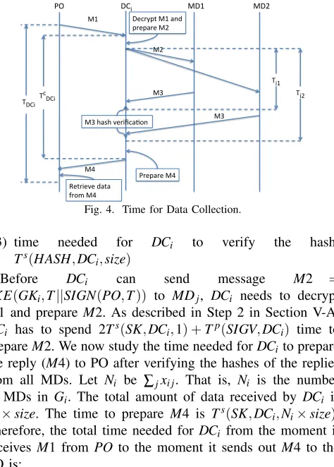
PO. To illustrate the process of time analysis, we present Fig. 4 to explain the different time components in the whole data collection process. In the picture, we assume there are only two MDs.
We first develop the time needed forDCi, after having
pre-paredM2, to send messageM2=SKE(GKi,T||SIGN(PO,T))
toMDj and verify the hash ofMDj’s reply, which is denoted
as Ti j.Ti j is the sum of the following components:
1) round-trip network delay between DCi and MDj:
2Tn(DCi,MDj)
2) time needed for MDj to generate reply M3 (Step 3):
Ts(SK,MD
j,1) +Tp(SIGV,MDj) +Ts(SK,MDj,size) +
2Ts(HASH,MDj,size)wheresizeis the size of the data
in terms of number of units.
PO DCi MD1 MD2
M1
M2
M3
M3
M4
Ti1
Ti2
M3 hash verifica5on Tc
DCi
TDCi
Decrypt M1 and prepare M2
Prepare M4 Retrieve data
[image:8.612.322.559.47.378.2]from M4
Fig. 4. Time for Data Collection.
3) time needed for DCi to verify the hash:
Ts(HASH,DC
i,size)
Before DCi can send message M2 =
SKE(GKi,T||SIGN(PO,T)) to MDj, DCi needs to decrypt
M1 and prepareM2. As described in Step 2 in Section V-A,
DCi has to spend 2Ts(SK,DCi,1) +Tp(SIGV,DCi) time to
prepareM2. We now study the time needed forDCito prepare
the reply (M4) to PO after verifying the hashes of the replies
from all MDs. Let Ni be ∑jxi j. That is, Ni is the number
of MDs in Gi. The total amount of data received by DCi is
Ni×size. The time to prepare M4 is Ts(SK,DCi,Ni×size).
Therefore, the total time needed for DCi from the moment it
receives M1 from PO to the moment it sends out M4 to the
PO is:
TDCc i = 2Ts(SK,DCi,1) +Tp(SIGV,DCi) +maxj{xi jTi j}
+Ts(SK,DCi,Ni×size)
We now study the time from the moment that PO sends
out M1 until the moment that PO successfully decrypts and
verifies the data carried in M4 sent by DCi. We denote
this time as TDCi. To retrieve the raw data from M4 =
SKE(GENKEY(KPO
DCi,T),PRODATA), PO first needs to
de-cryptM4 using GENKEY(KDCPO
i,T). It then needs to decrypt
and verify the hash carried inPRODATA. Therefore,TDCi is
TDCi = 2T
n(PO,DC
i) +TDCc i+
2Ts(SK,PO,Ni×size) +Ts(HASH,PO,Ni×size)
= f(i) +maxj{xi jTi j} (1)
where
f(i) = 2Ts(SK,DCi,1) +Tp(SIGV,DCi) +2Tn(PO,DCi)
+2Ts(SK,PO,Ni×size) +Ts(HASH,PO,Ni×size)
B. Problem Formulation
When PO wants to collect all data as soon as possible,
we should assign each MD to an appropriate DC such that
the maximum TDCi over all i∈D is minimized. Such an
objective leads to what is known in the literature as aminimax
problem. From Equation 1, we can simplify the terms into two major categories for the minimax optimization: One is
the maximizing component (maxj{xi jTi j}) and the other is
the summative part (f(i)). The former consists mostly of
the total completion time for data collection by a DC. The latter includes the processing time, including the cryptographic computation, whose total time will be a summation operation. In what follows, we will ignore the maximization components, as it is rather trivial to address alone, and concentrate on the summative part. Under a realistic data collection scenario, summative component will likely be the dominant term to determine the overall performance.
When the summative part is considered, the problem looks
very similar to the makespan minimization problem from
the scheduling theory [46], [47]. Scheduling theory considers problems where a set of jobs (tasks) are to be assigned to a set of machines or processors to satisfy an objective. One machine can only work on one job at a time. The well-established
3-field classification introduced in [48] uses α|β|γ notation,
where job, machine, and scheduling characteristics are denoted
by α, β, and γ, respectively. The summative part of our
objective function is denoted by Q||Cmax, where arbitrary
number of machines operating at different speeds must be used to complete a given set of tasks with the minimum makespan objective. This problem setting is also known in the literature
as uniform parallel machines [49]. In our problem, machines
are DCs, and tasks are MDs whose data need to be collected. The Integer Linear Programming (ILP) formulation for our summative part may be formulated as follows:
min max
∑
j
xi jti j (2)
s.t.
∑
j
xi j=1, ∀i∈D (3)
xi j∈ {0,1} ∀i∈D,∀j∈M (4)
wherexi j represents whether DCi is assigned to collect data
from MD j, andti j is the amount of the summative part of
the total data collection time of MD j’s data by DCi.
When we let Cmax represent the maximum data collection
time, the above formulation can be rewritten in a standard form as follows:
min Cmax (5)
s.t.
∑
j
xi j=1, ∀i∈D (6)
∑
j
xi jti j≤Cmax, ∀i∈D (7)
xi j∈ {0,1} ∀i∈D,∀j∈M (8)
The above problem can be shown to be strongly NP-Hard [50], [51] by a reduction from a 3-Partition problem [52]. Also note that this problem is a kind of the dual of the bin packing problem [50], [53].
As solving the ILP of minimum makespan is NP-hard by reduction from a 3-Partition problem, and thus making it unlikely that a polynomial algorithm exists, we develop a
greedy heuristic, Least Loaded DC First (L3F), to solve the
problem. We find the largest time for data collection for any
(DC,MD)pair, sayδ,µ. We assign MDµ to aDC that will
complete in the least time. Next, we pick the next largest time
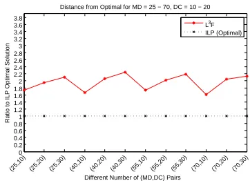
0 0.2 0.4 0.6 0.8 1 1.2 1.4 1.6 1.8 2 2.2 2.4 2.6 2.8 3 3.2 3.4 3.6 3.8
Distance from Optimal for MD = 25 − 70, DC = 10 − 20
Different Number of (MD,DC) Pairs
(25,10) (25,20) (25,30) (40,10) (40,20) (40,30) (55,10) (55,20) (55,30) (70,10) (70,20) (70,30)
Ratio to ILP Optimal Solution
[image:9.612.346.527.55.186.2]L3F ILP (Optimal)
Fig. 5. Ratio of total data collection time for L3F to Optimal ILP.
50 100 200 300 400 500 600 700 800 900 1000 100
200 300 400 500 600 700 800
Number of MDs
Total Time
Total Time for Greedy Longest to Least Loaded First
[image:9.612.338.529.225.378.2]DC=25 DC=50 DC=75 DC=100
Fig. 6. Performance of L3F in terms of total data collection time over
changing the number of MDs with 4 different number of DCs.
and assign it to the least loaded DC for the corresponding MD. We iterate until we deplete unassigned MDs. It is obvious
that the complexity of the algorithm isO(d). Due to the page
limitation, we omit the details of the full algorithm and refer the reader to [45].
VII. PERFORMANCEEVALUATION
[image:9.612.91.291.363.426.2]We have used CPLEX to solve the ILP formulations and implemented our approaches in C++. Since the problem is NP-Hard, the ILP formulation that can be solved by CPLEX hits a wall rather quickly: After about 70 MDs and 35 DCs, CPLEX started taking very long to yield any results. Thus, we have run some simulations up to 70 MDs and 35 DCs each with 30 runs to get an idea of the comparative performance results. The time for collecting data from MDs by DCs are randomly generated from a uniform probability distribution in the range of 10 to 100. The number of DCs took the values of 10, 20, and 30 while the number of MDs were assigned 25, 40, 55, and 70. All possible combinations were run for 30 times for statistical significance.
Figure 5 shows the performance of ILP and L3F for all 12
combinations of the number of MDs and DCs. It plots the total time values returned by the ILP from CPLEX as the reference
being a greedy algorithm, performed worse with an average distance ratio to the optimum of approximately 1.96.
For more MDs and DCs, ILP cannot yield results. Thus,
we only report L3F in extensive simulations with the number
of MDs going up to 1000 in increments of 50 starting from 50 and number of DCs at 25, 50, 75, 100. We had a total of
80 unique(MD,DC)pairs. Again, in order to attain statistical
significance, each combination pair was run 30 times. The time values for the data collection from MDs by DCs were generated using a uniform density function in the range of 10 to 100. Figure 6 displays the total time of data collection
for L3F over the number of MDs from 50 to 1000 for 25,
50, 75, and 100 DCs as separate lines. Except for when the number of DCs was equal to 25, the total time increases with respect to larger number of MDs is with moderate slope. When DC is equal to 25, the increase is rather steep but still linear. This behavior might indicate that when there is significant imbalance between the number of DCs and MDs the total time to collect data may adversely affected. This point of operating overload is hard to have a threshold value to associate with but nevertheless should be considered.
VIII. CONCLUSION
The bidirectional power and information flow of the Smart Grid vision has led to the proliferation of a variety of measure-ment devices. These devices generate unprecedented amounts of data. The existing, legacy protocols are not capable of addressing this new phenomenon. In order to address this challenge, we propose a comprehensive and secure com-munications protocol to enable a power operator to collect data from measurement devices in a practical, scalable, and efficient manner under a hierarchical data collection model. Intermediary nodes are assumed to follow the honest-but-curious model in relaying the data. Thus, our protocol paves the way for third party service provisioning, as envisioned by the NIST Smart Grid Framework. Examples of such services include outsourcing data collection by third party DCs, utiliz-ing cloud compututiliz-ing services for data storage and processutiliz-ing, etc. We formulate an optimization problem for associating the intermediary relay nodes with measurement devices for data collection in order to minimize the total data collection time. The problem is intractable and thus we present a heuristic algorithm with good approximation and fast convergence.
REFERENCES
[1] N. Kayastha, D. Niyato, E. Hossain, and Z. Han, “Smart grid sensor
data collection, communication, and networking: a tutorial,” Wireless
Communications and Mobile Computing, pp. n/a–n/a, 2012.
[2] National Institute of Standards and Technology. (2013, October) NIST Framework and Roadmap for Smart Grid Interoperability Standards, Release 3.0. Smart Grid Interoperability Panel (SGIP).
[3] X. Fang, S. Misra, G. Xue, and D. Yang, “Managing smart grid
infor-mation in the cloud: opportunities, model, and applications,”Network,
IEEE, vol. 26, no. 4, pp. 32–38, July 2012.
[4] S. Bera, S. Misra, and J. Rodrigues, “Cloud computing applications for
smart grid: A survey,”IEEE Tran. on Par. and Dist. Sys., no. 99, 2014.
[5] R. Tabassum, K. Nahrstedt, E. Rogers, and K.-S. Lui, “SCAPACH: Scal-able password-changing protocol for smart grid device authentication,”
inProc. of Third International Workshop on Privacy, Security, and Trust
in Mobile and Wireless Systems (MobiPST), 2013.
[6] RFC 5246, “The transport layer security (tls) protocol version 1.2,” 2008.
[7] Y.-J. Kim, V. Kolesnikov, and M. Thottan, “Resilient end-to-end mes-sage protection for large-scale cyber-physical system communications,”
in Smart Grid Communications (SmartGridComm), 2012 IEEE Third
International Conference on, Nov 2012, pp. 193–198.
[8] IEEE 1815-2012, “Dnp3 secure authentication version 5,” 2011.
[9] International Electrotechnical Commission’s (IEC) Technical Committee 57 (TC57). (2003) IEC 61850, Power Utility Automation .
[10] W. Wang and Z. Lu, “Cyber security in the smart grid: Survey and
challenges,”Computer Networks, vol. 57, no. 5, pp. 1344 – 1371, 2013.
[11] Y.-J. Kim, V. Kolesnikov, H. Kim, and M. Thottan, “SSTP: a scalable
and secure transport protocol for smart grid data collection,” inProc. of
IEEE SmartGridComm, 2011.
[12] T. Khalifa, K. Naik, M. Alsabaan, A. Nayak, and N. Goel, “Transport
protocol for smart grid infrastructure,” in Proc. of IEEE International
Conference on Ubiquitous and Future Networks, 2010.
[13] X. Long, D. Tipper, and Y. Qian, “An advanced key management
scheme for secure smart grid communications,” in Proc. of IEEE
SmartGridComm, 2013.
[14] N. Liu, J. Chen, L. Zhu, J. Zhang, and Y. He, “A key management scheme for secure communications of advanced metering infrastructure
in smart grid,”IEEE Tran. on Ind. Elect., vol. 60, no. 10, 2013.
[15] D. Wu and C. Zhou, “Fault-tolerant and scalable key management for
smart grid,”IEEE Trans. on Smart Grid, vol. 2, no. 2, June 2011.
[16] M. M. Fouda, Z. M. Fadlullah, N. Kato, R. Lu, and X. Shen, “A lightweight message authentication scheme for smart grid
communica-tions,”IEEE Tran. on Smart Grid, vol. 2, no. 4, Dec. 2011.
[17] C. Bekara, T. Luckenbach, and K. Bekara, “A privacy preserving and secure authentication protocol for the advanced metering infrastructure
with non-repudiation service,” inProc. of ENERGY, 2012.
[18] Y. Law, G. Kounga, and A. Lo, “WAKE: Key management scheme for
wide-area measurement systems in smart grid,”IEEE Comm. Mag., Jan.
2013.
[19] N. Liu, J. Chen, L. Zhu, J. Zhang, and Y. He, “A key management scheme for secure communications of advanced metering infrastructure
in smart grid,”IEEE Tran. on Industrial Electronics, vol. 60, no. 10, pp.
4746–4756, Oct 2013.
[20] A. Seshadri, M. Luk, and A. Perrig, “Sake: Software attestation for key
establishment in sensor networks,” inProc. of International Conference
on Distributed Computing in Sensor Systems, 2008.
[21] H. Nicanfar and V. Leung, “Multilayer consensus ecc-based password authenticated key-exchange (mcepak) protocol for smart grid system,”
IEEE Tran. on Smart Grid, vol. 4, no. 1, 2013.
[22] A. Perrig, R. Szewczyk, J. D. Tygar, V. Wen, and D. E. Culler, “Spins:
Security protocols for sensor networks,”Wirel. Netw., vol. 8, no. 5, pp.
521–534, Sep. 2002.
[23] S. Uludag, S. Zeadally, and M. Badra, “Techniques, Taxonomy, and
Challenges of Privacy Protection in Smart Grid,” inPrivacy in a Digital,
Networked World. Springer London, Feb. 2015.
[24] W. He, X. Liu, H. Nguyen, K. Nahrstedt, and T. Abdelzaher, “Pda: Privacy-preserving data aggregation in wireless sensor networks,” in
IEEE INFOCOM 2007, May 2007, pp. 2045–2053.
[25] W. He, H. Nguyen, X. Liu, K. Nahrstedt, and T. Abdelzaher, “iPDA: An integrity-protecting private data aggregation scheme for wireless sensor
networks,” inIEEE MILCOM 2008, Nov 2008, pp. 1–7.
[26] T. Feng, C. Wang, W. Zhang, and L. Ruan, “Confidentiality protection
for distributed sensor data aggregation,” inIEEE INFOCOM, April 2008.
[27] M. Groat, W. He, and S. Forrest, “Kipda: k-indistinguishable
privacy-preserving data aggregation in wireless sensor networks,” in IEEE
INFOCOM, April 2011, pp. 2024–2032.
[28] Y. Yan, Y. Qian, and H. Sharif, “A secure and reliable in-network col-laborative communication scheme for advanced metering infrastructure
in smart grid,” inIEEE WCNC, March 2011, pp. 909–914.
[29] K. Kursawe, G. Danezis, and M. Kohlweiss, “Privacy-friendly
aggrega-tion for the smart-grid,” inPrivacy Enhancing Technologies. Springer,
2011, vol. 6794, pp. 175–191.
[30] C. Rottondi, G. Verticale, and C. Krauss, “Distributed privacy-preserving
aggregation of metering data in smart grids,”IEEE JSAC, vol. 31, no. 7,
pp. 1342–1354, July 2013.
[31] H. Nicanfar, A. Alasaad, P. Talebifard, and V. Leung, “Network coding
based encryption system for advanced metering infrastructure,” inIEEE
[32] D. Niyato and P. Wang, “Cooperative transmission for meter data
collection in smart grid,” Communications Magazine, IEEE, vol. 50,
no. 4, pp. 90–97, April 2012.
[33] S. Shao, S. Guo, X. Qiu, L. Meng, Y. Jiao, and W. Wei, “Traffic schedul-ing for wireless meter data collection in smart grid communication
network,” inComputing, Communication and Networking Technologies
(ICCCNT), 2014 International Conference on, July 2014, pp. 1–7.
[34] F. Li, B. Luo, and P. Liu, “Secure information aggregation for smart
grids using homomorphic encryption,” inSmart Grid Communications
(SmartGridComm), 2010 First IEEE International Conference on, Oct
2010, pp. 327–332.
[35] N. Yukun, T. Xiaobin, C. Shi, W. Haifeng, Y. Kai, and B. Zhiyong, “A security privacy protection scheme for data collection of smart meters
based on homomorphic encryption,” inEUROCON, 2013 IEEE, July
2013, pp. 1401–1405.
[36] J. Kamto, L. Qian, J. Fuller, J. Attia, and Y. Qian, “Key distribution and management for power aggregation and accountability in advance
meter-ing infrastructure,” inSmart Grid Communications (SmartGridComm),
2012 IEEE Third International Conference on, Nov 2012, pp. 360–365.
[37] F. Li and B. Luo, “Preserving data integrity for smart grid data
aggregation,” inSmart Grid Communications (SmartGridComm), 2012
IEEE Third International Conference on, Nov 2012, pp. 366–371.
[38] T. Chim, S. Yiu, V. Li, C. Hui, and J. Zhong, “PRGA: Privacy-preserving Recording amp; Gateway-assisted Authentication of Power
Usage Information for Smart Grid,”IEEE Tran. on Dependable and
Secure Computing, vol. PP, p. 1, 2014.
[39] L. Chen, R. Lu, and Z. Cao, “PDAFT: A privacy-preserving data aggregation scheme with fault tolerance for smart grid communications,”
Peer-to-Peer Networking and Applications, pp. 1–11, 2014.
[40] J. Hur, “Attribute-based secure data sharing with hidden policies in smart
grid,”IEEE Tran. on Par. and Dist. Sys., vol. 24, no. 11, 2013.
[41] P. Li, S. Guo, and Z. Cheng, “Joint optimization of electricity and
communication cost for meter data collection in smart grid,”IEEE Tran.
on Emerging Topics in Computing, vol. 1, no. 2, pp. 297–306, Dec 2013.
[42] P. Li and S. Guo, “Delay minimization for reliable data collection on
overhead transmission lines in smart grid,” inComputing,
Communica-tions and IT ApplicaCommunica-tions Conference (ComComAp), 2013, April 2013,
pp. 147–152.
[43] M. Qiu, H. Su, M. Chen, Z. Ming, and L. Yang, “Balance of security strength and energy for a pmu monitoring system in smart grid,”
Communications Magazine, IEEE, vol. 50, no. 5, pp. 142–149, May
2012.
[44] G. Dan, K.-S. Lui, R. Tabassum, Q. Zhu, and K. Nahrstedt, “SELINDA: A secure, scalable and light-weight data collection protocol for smart
grids,” inProc. of IEEE SmartGridComm, 2013.
[45] S. Uludag, K.-S. Lui, W. Ren, and K. Nahrstedt, “Secure and Scalable Communications Protocol for Data Collection with Time Minimization in the Smart Grid,” Department of Computer Science, University of Illinois at Urbana-Champaign, Tech. Rep. 2014-07-16, July 2014. [Online]. Available: http://hdl.handle.net/2142/49985
[46] J. Y.-T. Leung, Handbook of scheduling : algorithms, models, and
performance analysis. Boca Raton, Fla.: Chapman & Hall/CRC, 2004.
[47] M. Pinedo,Scheduling: Theory, Algorithms, and Systems. Springer,
2008.
[48] R. Graham, E. Lawler, J. Lenstra, and A. Kan, “Optimization
and approximation in deterministic sequencing and scheduling:
a survey,” ser. Annals of Discrete Mathematics. Elsevier,
1979, vol. 5, no. 2, pp. 287 – 326. [Online]. Available:
http://www.sciencedirect.com/science/article/pii/S016750600870356X
[49] P. Brucker,Scheduling Algorithms. Springer, 2007. [Online]. Available:
http://books.google.com/books?id=FrUytMqlCv8C
[50] J. Y.-T. Leung, “Bin packing with restricted
piece sizes,” Information Processing Letters, vol. 31,
no. 3, pp. 145 – 149, 1989. [Online]. Available:
http://www.sciencedirect.com/science/article/pii/0020019089902238 [51] D. S. Hochbaum and D. B. Shmoys, “Using dual approximation
algorithms for scheduling problems theoretical and practical results,”
J. ACM, vol. 34, no. 1, pp. 144–162, Jan. 1987. [Online]. Available:
http://doi.acm.org/10.1145/7531.7535
[52] M. R. Garey and D. S. Johnson,Computers and Intractability: A Guide
to the Theory of NP-Completeness. New York, NY, USA: W. H.
Freeman & Co., 1979.
[53] E. Coffman, Jr., M. Garey, and D. Johnson, “An application
of bin-packing to multiprocessor scheduling,” SIAM Journal on
Computing, vol. 7, no. 1, pp. 1–17, 1978. [Online]. Available: