2019 International Conference on Artificial Intelligence, Control and Automation Engineering (AICAE 2019) ISBN: 978-1-60595-643-5
Research on Dynamic Characteristics of Split TBM Cutterhead
Based on Similarity Theory
Peng GAO, Tian-yu DU, Jian-fu ZHANG
*, Yun-jian ZHA and Ping-fa FENG
Department of Mechanical Engineering, Tsinghua University, Beijing 100084, China
*Corresponding author
Keywords: Split TBM cutterhead, Dynamic characteristics, Similarity theory, Finite element analysis.
Abstract.Cutterhead with disc cutters is a key component of tunnel boring machine (TBM), and its dynamic characteristics greatly influences the cutting performance of the equipment rock disc cutters. This study investigated the dynamic characteristics of split TBM cutterhead under bolted connection based on the similarity theory. A simplified and scale similarity of split cutterhead was proposed. Based on a virtual material method, a simulation model was established and its dynamic characteristic was analyzed for each block of scaled cutterhead. Dynamic testing experiments of the center block, side block and scaled cutterhead were carried out to achieve the vibration mode and frequency. The results show that the errors of the center block and side block between theoretical natural frequencies and experimental ones are less than 7%, and the theoretical mode shapes are in agreement with the experiments. Besides, the errors between experiment and simulation of the scaled cutterhead are less than 15%, and the virtual material method is verified. The similarity theory and the virtual material method would be used to investigate the dynamic characteristics of split TBM cutterhead.
Introduction
Tunnel boring machine (TBM) is widespread applied in urban underground, mountain railway and subway tunnels. Mechanized excavation by means of tunnel TBM becomes the most common solution for hard rock tunneling [1]. Cutterhead is a key component of TBM, which can crush and cut rock with disc cutters mounted on its panel [2]. The manufacture of the large cutterhead is divided into parts fixed by bolt welding connection. Rock breaking force of TBM hob is a dynamic process with strong mutation and randomness. The problems of cutterhead such as cutter falling off and cutterhead splitting joint cracking often occur, which are closely related to the dynamic characteristics of cutterhead. Therefore, it is necessary to study the dynamic characteristics of the cutterhead.
characteristics of the cutterhead have a great influence on its structural stiffness and dynamic performance.
In the study of bolted joint characteristics, Shi et al. [7] proposed a simplified shear behavior model and hysteretic criterion of high strength bolted connection, and reported that the shear behavior presents the isotropic hardening characteristics under cyclic loading. Kim et al. [8] reported solid bolt finite element model is most accurately predict the physical behavior of bolted joint structure compared to coupled bolt model, spider bolt model and no-bolt model. Liao et al. [9-10] proposed a virtual gradient material model to improve dynamic modeling of the bolted joint based on Hertz contact theory and fractal geometry theory, and reported that the theoretical mode shapes were in good agreement with the experimental mode shapes. Tian et al. [11] proposed an analytic method of virtual material hypothesis-based dynamic modeling on fixed joint interface in machine tools to improve the modeling accuracy. The results show that the errors between theoretical natural frequencies and experimental ones are less than 9%, and the theoretical mode shapes are in agreement with the experiments. However, few researches considered the effects of the split connection and bolted joint interface on dynamic behavior and vibration characteristics of the cutterhead.
This paper investigated the dynamic characteristics of split TBM cutterhead based on scale similarity theory. The scaled TBM cutterhead was modeled and manufactured. Based on a virtual material method, a free modal simulation analysis of the scaled cutterhead was carried out. The dynamic testing experiments of the scaled cutterhead were carried out. The established simulation model of the scaled cutterhead was also verified.
Simplified and Scale Similarity of Split Cutterhead
Simplified Equivalent of Split Cutterhead
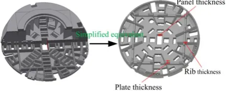
Due to large diameter of split TBM cutterhead, it is too difficult and expensive to conduct the relevant experiment research. The similarity theory was introduced to investigate the dynamic characteristics split TBM cutterhead [12]. The structure of split TBM cutterhead is complex, and it has many internal ribs. It is inconvenient to manufacture when the cutterhead is scaled to smaller size, so it needs to be simplified. The simplification principles are shown in Figure 1. To facilitate the equivalent the loading, the simplified cutterhead only retains hob cutter groove regardless of the cutter. The small bosses, small holes and small ribs are removed in the scale cutterhead. Considering the equivalent of the box-type structural ribs, the 12 main ribs are retained. By changing the thickness of panel, the rib and the block connection plate, the equivalent cutterhead has the same stiffness as the original cutterhead in axial and torsional directions. Firstly, in the Workbench, the
axial force of 105 N and axial torque of 105 N·m are applied to the original model to obtain force and
[image:2.595.182.414.663.757.2]torsional deformation along axial direction. The three parameters are optimized by the response surface optimization in Workbench. The thickness ranges of panel, rib, and plate are limited to the (288 mm, 352 mm), (45 mm, 55 mm), (126 mm, 154 mm), respectively. By the calculation, the panel thickness 320 mm, rib thickness 50 mm and plate thickness 140 mm are obtained. After the stiffness equivalent of disc panel and rib, the structure of simplified cutterhead is scaled by the similarity theory.
Scale Similarity of Split Cutterhead
The scaled experiment research is significant for the analysis of the cutterhead. For it large-scale and hard experiment, the cutterhead experiment can be carried out based on scale similarity theory, and the dynamic characteristics of original cutterhead are achieved by the scaled cutterhead. The experiment of scaled cutterhead has the advantages of data accurate, economical and not susceptible to environmental interference.
During tunneling process, the loading of the cutterhead is random and catastrophic. The similar model of the cutterhead must meet the requirements of structural dynamic similarity. The model is proportional to inertia force of the prototype at the corresponding position with the same direction. The physical similarity constants of scaled cutterhead model was presented to guarantee the similarity of dynamic characteristics of the cutterhead. According to the structure features, the dynamic characteristics of the cutterhead are affected by the physical parameters of the cutterhead
weight q, cutterhead size L, external load F, stress σ, strain ε and elastic modulus E. The total number
of physical quantities is n=6, and the number of basic dimensions and non-dimensional physical
quantities are k=2 and M=1, respectively. The (n-k)=4 similarity criteria can be established. The
functional relations are established based on F, L basic quantities. The dynamic characteristics
parameters of the cutterhead were analyzed including external force F, linear dimension L,
displacement x, frequency w, velocity v, acceleration a, density ρ, elastic modulus E, Poisson ratio υ.
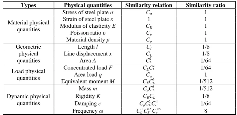
Based on the dynamic similarity theory of the scaled cutterhead, the similarity sets of various physical parameters related to the excavation process of the scaled cutterhead can be determined, as shown in Table 1. It can be seen that the modal frequency of the scale model is 8 times that of the
original model, the similarity constant of modal mass is 3
1 512
m L
C C C , the similarity constant of
modal stiffness is 2
1 8
K m
[image:3.595.98.495.421.614.2]C C C , and the dimensionless mode shape is C1.
Table 1. Physical parameters of similarity scaled cutterhead.
Types Physical quantities Similarity relation Similarity ratio
Material physical quantities
Stress of steel plate σ Cσ 1
Strain of steel plate ε 1 1
Modulus of elasticity E CE 1
Poisson ratio υ Cυ 1
Material density ρ Cρ 1
Geometric physical quantities
Length l Cl 1/8
Line displacement x CL 1/8
Area A C2
L 1/64
Load physical quantities
Concentrated load F CEC
2
L 1/64
Area load q Cq 1
Equivalent moment M CEC
3
L 1/512
Dynamic physical quantities
Mass m CρC3L 1/512
Rigidity K CECL 1/8
Damping c CρC2LC
-1
E 1/64
Frequency ω C-1
LC 0.5 E C
-0.5
ρ 8
Figure 2. Modeling and manufacturing of scaled cutterhead.
Modeling of Split Cutterhead by Virtual Material Method
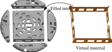
A free modal simulation analysis of the scaled cutterhead was carried out in ANSYS Workbench to study the dynamic characteristics of the cutterhead. An isotropic virtual material model was used to model the bolted joint surface in the split cutterhead. The virtual material layer with corresponding thickness was created at the bolt joint between side block and center block, side block and side block. The virtual material layer was filled into the joint part between the blocks as shown in Figure 3.
填充
虚拟材料层
填充
虚拟材料层 填充
虚拟材料层 Filled into
Virtual material
Figure 3. Split TBM cutterhead model with virtual material layer.
The virtual material model is established based on Hertz contact theory and fractal theory. A plane joint surface is composed of many micro asperities in microscale, and the asperities on a rough surface can be assumed spherical. The statistical distribution of the truncated micro-contact asperity
area a' is [13]
1 0.5 0.5 1 0.5
( ) 0.5 D D D 0
L L
n a D a a a a (1)
Where, D is the fractal dimension, aLis the largest truncated area of micro-contact asperity.
is
the domain extension factor for micro-contact size distribution, and can be obtained as
( 2)/1 0.5 0.5
1
1 2
D D
D D
D D
D
(2)
According to Hertz contact theory and fractal theory, the normal contact force at an elastic micro-contact asperity can be obtained as
*
1.5 0.5 1
4
3 2
D D
e
E
f G a
(3)
Where, E* is the equivalent elastic modulus, G is the fractal roughness.
The normal force on a plastic microcontact asperity fp is
p
f Ha (4)
Where, H is the Brinell hardness.
[image:4.595.204.392.318.405.2]1
2 2 1
2 * 2 17 50( ) D f y c k a G E (5)
The total contact load F can be written as [9]
0 L c c a a e p a
F
f n a da
f n a da (6)
* 1 1 0.5 1 0.5
0.5 1.5 1.5 0.5 1 0.5
0.25 * 0.5
0.75 0.75 0.25
2
( ) ( ) ( ) ( ) ( ) 1.5
2 3 2 (1.5 )
= 2.0007
ln 1.5 2.0007 1.5
2
D D D
D D D D D
L L c L c
L
L L c
c
DE G DH
a a a a a D
D D
F
a E G
a H a a D
a (7)
The normal contact stiffness knat each microcontact can be written as
* 1/ 2 4 3 2 3 2 n
df E D
k a
d D
(8)
The macro scale normal contact stiffness Kn can be obtained by
* 1 0.5 0.5
0.5 0.5 0.5 0.5 ( )
( ) ( ) ( )
2 0.5 0.5
L c
D D
a D D
L
n a n L c
E D a
K k n a da a a
D
(9)According to previous research [9, 11], the whole tangential contact stiffness Kτ is given by
* 1 0.5
0.5 0.5 0.5 0.5 0.5 4 2
( ) ( ) ( )
1 D
D D D
L L c
G D
K a a a
D
(10)
The stiffness of the joint surface is affected by macro surface morphology and flatness tolerance. The influencing factors of macroscopic morphology on montact stiffness is 0.6 [15]. Due to the large size of the scaled cutterhead, the flatness tolerance grade of plane is IT9, and the effect of flatness tolerance on normal contact stiffness [16]
27.62 36.22 n p
(11)
Where, pnisthe normal contact pressure of joint surface (Unit MPa).
Considering the effects of macro surface morphology and flatness tolerance, the elastic modulus
Ejoint of joint surface is given by
Jo int 1 1
n u f a K t E A
(12)
Where, Aa is the apparent contact area, t is thickness of virtual material.
Likewise, the shear modulus Gjointcan be obtained as
Jo int a K t G A
(13)
In the virtual material model, the fractal dimension and roughness need to be obtained by the joint surface profile. The profile of the joint surface was measured before the split TBM cutterhead was assembled. The fractal dimension and roughness of the joint surface in cutterhead are calculated by the structure function method. When two rough contact surfaces are equivalent to a deformed surface and a rigid plane. Therefore, if the two contact surfaces have the same profile
characteristics, then D1 is equal to D2 and G1 is equal to G2, and it follows that [9]. The equivalent
fractal dimension and the fractal rough surface D and Gare
1 2
DD D (14)
2 2 2 2 2 2
1 2
D D D
The average value of the five fractal dimension and roughness calculated values at different
locations are taken as the parameters of the joint surface. The average of 25 times D1 = 1.6378 and
7
1 2.77 10
G are obtained by calculation. The equivalent fractal dimension and the fractal rough
surface are D=1.6378 and 7
4.7695 10
G .
The material properties of each side block and center block are set as steel Q345D properties. The area of virtual material is accordance with the nominal area of the contact region. The thickness of the virtual material layer was 1 mm. The contact simulations are performed for surfaces with
apparent contact area Aa= 0.078 m2. The joint material is machined with Young’s modulus E1=206
GPa, Poisson ratio v=0.28, Brinell hardness H=500 MPa and Density 7850 kg/m3. The elastic
modulus 7
Joint 2.6242 10
E Pa and the shear modulus 7
Joint 4.5439 10
G Pa were obtained. In the
simulation, the modal analysis of the split TBM cutterhead was carried out. The mesh size of the side block, center block and scaled cutterhead was 10 mm, and the hexahedron element was used to mesh.
Dynamic Experiments of Scaled Cutterhead
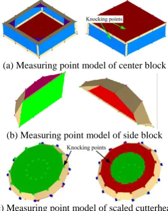
The free modal testing model was established in the LMS Desktop. Different components were divided based on the direction of each test object surface, and the coordinates of each component was defined in global coordinate system. The coordinates of nodes were defined in the corresponding components, and the measuring model was established by connecting each node. The measuring points were generally distributed in the center and edge of measuring surface. The corresponding relationship between measuring points and geometric model points was established. The measuring point model was established in the LMS Desktop based on the center block structure, as shown in Figure 4(a). The measurement point model of central block was composed of 6 components and 76 nodes. The measuring point model of side block was shown in Figure 4(b), and the model consists of 4 components and 32 nodes. Besides, the measuring point model of scaled cutterhead was shown in Figure 4(c), and the model consists of 3 components and 60 nodes.
(a) Measuring point model of center block
(b) Measuring point model of side block
[image:6.595.210.384.447.665.2](c) Measuring point model of scaled cutterhead
Figure 4. Measuring point model of center block, side block and scaled cutterhead.
accelerometer (PCB 356A16). The sensitivity of impact hammer transducer is 12.36 mV/N, and the sensitivity of acceleration transducer of the XYZ axis are 102.2 mV/g, 104 mV/g and 101.8 mV/g, respectively. Each measuring point was measured five times, and the average value was the last value. The acceleration sensor was arranged on measuring point, and the sensor direction was corresponded with the model coordinate system. Besides, the PCB force hammer was used to knock the reference points, and the accelerometer was used to measure the response of the measuring point. The vibration characteristics of the measuring points were tested by moving the accelerometer.
Data acquisition system
Computer LMS test.lab Rubber rope
TBM cutterhead
Hammer
Acceleration transducer
(a) (b)
[image:7.595.181.419.172.256.2](c) (d)
Figure 5. Modal test of TBM split cutterhead (a) Modal test experiment of TBM split cutterhead, (b) Installation of split cutterhead, (c) Hanging of split cutterhead, (c) Amplitude frequency response.
Results and Discussion
Simulation Dynamic Characteristics
The first six order simulation modal shapes of center block of the scaled cutterhead are shown in Figure 6. The simulation results show that the first six free frequencies of the center block are 464.5 Hz, 683.1 Hz, 746.3 Hz, 748.1 Hz, 932.6 Hz, 991.2 Hz, respectively. For the modal shapes, the first mode shape of vibration is bending vibration of four corners around the center block. The second mode shape of vibration is the bending vibration around the center in the middle of the four sides of the center block. The third modal shape is torsional vibration around the diagonal of the center block panel. The fourth modal shape is torsional vibration of around the diagonal of center block panel. The fifth modal shape is bending and torsional vibration of the back plate of the center block in XZ plane, and the sixth modal shape is the up and down vibration of the central block.
The simulation modal shapes of the side block are also shown in Figure 7. The first six free frequencies of the center block are 1149.7 Hz, 1242.9 Hz, 1503.6 Hz, 1886.8 Hz, 2091.2 Hz, 2343.5 Hz, respectively. It can be seen that the mode shape of first order natural frequency is bending vibration around the Z axis on both sides of the side block. The second mode shape is the torsional vibration around the X axis on both sides of the block. The third mode shape is bending vibration of the left edge of the side block in the XY plane. The fourth mode shape is a torsional swing of right side of the side block around the X axis. The fifth mode shape is bending vibration of the left edge of the side block around the Y axis. The sixth mode shape is XY swing in the plane.
(a) First (b) Second (c) Third
(d) Fourth (e) Fifth (f) Sixth
[image:7.595.174.425.599.738.2](a) First (b) Second (c) Third
[image:8.595.171.425.70.209.2](d) Fourth (e) Fifth (f) Sixth
Figure 7. Simulation modal shapes of scaled cutterhead side block.
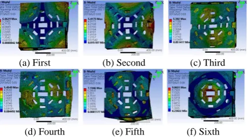
A virtual material method is used to model joint surface of the scaled cutterhead, and the mode shapes of natural frequencies is shown in Figure 8. The simulation results show that the first six free frequencies of the scaled cutterhead are 531.8 Hz, 587.2 Hz, 770.1 Hz, 772.8 Hz, 874.3 Hz, 971.2 Hz. It can be seen that the first natural mode shape of vibration is torsional vibration of the cutterhead around the bisector of the angle of X axis and Y axis. The second mode of shape vibration is torsional vibration of the cutterhead around the X axis Y axis. The third mode shape of vibration is the torsional vibration of the Y axis around the center of the cutterhead in the middle of the cutterhead. The fourth mode shape of vibration is the torsional vibration around the center of the cutterhead. The fifth mode shape is the up and down vibration of the central block. The sixth modal shape is bending and torsional vibration of the back plate of the center block.
(a) First (b) Second (c) Third
(d) Fourth (e) Fifth (f) Sixth
Figure 8. Simulation modal shapes of scaled cutterhead.
To verify the scale similarity of split cutterhead, the simulation modal of center block, side block and simplified original cutterhead are also conducted. The material quantities scale equivalent proportion of the scaled cutterhead is 1 (Table 1) and the virtual material of scaled cutterhead was used.
Experiment Dynamic Characteristics
[image:8.595.174.422.378.525.2]Figure 9. Amplitude frequency response of center block.
(a) First (b) Second (c) Third
[image:9.595.193.405.192.351.2](d) Fourth (e) Fifth (f) Sixth
Figure 10. Experiment modal shapes of center block.
The amplitude frequency response of one of the side blocks is shown in Figure 11. The mode shapes of natural frequencies are obtained by selecting the corresponding frequencies. The mode shapes corresponding to the first 6 natural frequencies of side block are shown in Figure 12. It can be seen that the first 6 natural frequencies are identified, and the mode shapes of natural frequencies are obtained by selecting corresponding frequencies. The mode shape of first order natural frequency is the bending vibration around the Z axis on both sides of the side block, and it is consistent with the simulation results (Figure 7(a)). Besides, the other mode shapes also are consistent with the simulation results. The first order natural frequency is 1119 Hz, the damping ratio is 0.23%. The second order natural frequency and damping ratio are 1229 Hz and 0.24%. The third natural frequency and damping ratio are 1462 Hz and 0.24%. The fourth natural frequency and damping ratio are 1805 Hz and 0.23%. The fifth natural frequency and damping ratio are 2038 Hz and 0.30%. The sixth order natural frequency and damping ratio are 2206 Hz and 0.21%.
Figure 11. Amplitude frequency response of side block.
(a) First (b) Second (c) Third
(d) Fourth (e) Fifth (f) Sixth
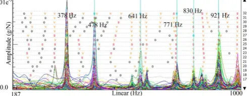
[image:9.595.191.411.542.650.2] [image:9.595.188.411.669.777.2]The amplitude frequency response of one of the scaled cutterhead is shown in Figure 13. The mode shapes corresponding to the first 6 natural frequencies of the scaled cutterhead are shown in Figure 14. The mode shapes of natural frequencies were obtained by selecting the corresponding frequencies. It can be seen that the first natural frequency and damping ratio are 378 Hz and 0.97%, respectively, and the mode of vibration is torsional vibration of the cutterhead around the bisector of the angle of X axis and Y axis. The second order natural frequency and damping ratio are 478 Hz and 0.51%, respectively, and the mode of vibration is torsional vibration of the cutterhead around the X axis Y axis. The third order natural frequency and damping ratio are 641 Hz and 1.04%, respectively, and the mode of vibration is the torsional vibration of the Y axis around the center of the cutterhead in the middle of the cutterhead.
Figure 13. Amplitude frequency response of scaled cutterhead.
(a) First (b) Second (c) Third
[image:10.595.174.421.270.467.2](d) Fourth (e) Fifth (f) Sixth
Figure 14. Experiment modal shapes of scaled cutterhead.
Comparation of Simulation and Experiment
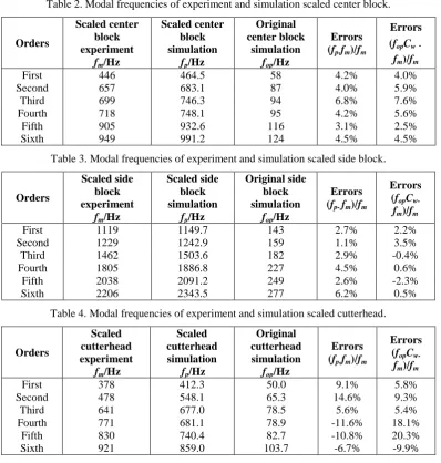
The experiment modal frequencies of the center block in scaled cutterhead compared to that of the simulation scaled center block are shown in Table 2. Besides, the experiment modal frequencies of the scaled cutterhead side block compared to that of the scaled simulation cutterhead are also showed in Table 3. It can be seen that the simulation results of the scaled center and side block are in good agreement with that of the experimental results. In terms of modal frequencies, the first six natural frequencies of the scaled center and side block measured by experiments are in good agreement with the first six natural frequencies of the scaled center and side block. The scaled center and side block errors between experiment and simulation are less than 7%. The errors between experiments and simulation are small. Besides, the errors between the scaled side block experiment and original center block simulation are less than 8%. The modal frequencies of scaled center block experiment are 8 times that of the original center block simulation. This verifies the scale similarity of the split cutterhead.
boundary. Moreover, compared to the center and side block, the number of welding seams and welding residual deformation of the cutterhead under bolted connection increase, so the effects of welding seams and welding residual deformation on dynamic characteristics of the cutterhead is larger. However, the simulation results of the scaled cutterhead are consistent with the experiment results, and the transversely isotropic virtual material model is verified on the scaled cutterhead experiment.
Table 2. Modal frequencies of experiment and simulation scaled center block.
Orders
Scaled center block experiment
fm/Hz
Scaled center block simulation
fp/Hz
Original center block
simulation
fop/Hz
Errors (fp-fm)/fm
Errors (fopCw-
fm)/fm
First 446 464.5 58 4.2% 4.0%
Second 657 683.1 87 4.0% 5.9%
Third 699 746.3 94 6.8% 7.6%
Fourth 718 748.1 95 4.2% 5.6%
Fifth 905 932.6 116 3.1% 2.5%
Sixth 949 991.2 124 4.5% 4.5%
Table 3. Modal frequencies of experiment and simulation scaled side block.
Orders
Scaled side block experiment
fm/Hz
Scaled side block simulation
fp/Hz
Original side block simulation
fop/Hz
Errors (fp- fm)/fm
Errors (fopC
w-fm)/fm
First 1119 1149.7 143 2.7% 2.2%
Second 1229 1242.9 159 1.1% 3.5%
Third 1462 1503.6 182 2.9% -0.4%
Fourth 1805 1886.8 227 4.5% 0.6%
Fifth 2038 2091.2 249 2.6% -2.3%
Sixth 2206 2343.5 277 6.2% 0.5%
Table 4. Modal frequencies of experiment and simulation scaled cutterhead.
Orders
Scaled cutterhead experiment
fm/Hz
Scaled cutterhead simulation
fp/Hz
Original cutterhead simulation
fop/Hz
Errors (fp-fm)/fm
Errors (fopC
w-fm)/fm
First 378 412.3 50.0 9.1% 5.8%
Second 478 548.1 65.3 14.6% 9.3%
Third 641 677.0 78.5 5.6% 5.4%
Fourth 771 681.1 78.9 -11.6% 18.1%
Fifth 830 740.4 82.7 -10.8% 20.3%
Sixth 921 859.0 103.7 -6.7% -9.9%
Summary
The dynamic characteristics of split TBM cutterhead has a great influence the cutting performance of the equipment rock disc cutters. To study the dynamic characteristics of TBM cutterhead, a split TBM scaled cutterhead under bolted connection was established based on similarity theory. A virtual material model was established in the simulation of scaled cutterhead. The dynamic characteristics of the center block, side block and scaled cutterhead were investigated by simulation and experiment. The results showed the natural frequency errors of the center block and side block between experiment and simulation are less than 7% and 6%, respectively. The errors between the experiment and simulation of the scaled cutterhead are less than 15%. All the theoretical mode shapes are in agreement with the experiments. The virtual material of the scaled cutterhead is verified by comparing the results of experiment. The similarity theory and the virtual material model provide a method to analyze the dynamic behavior of the split TBM cutterhead.
Acknowledgment
This research was financially supported by the National Natural Science Foundation of China (Grant No. 51575301).
References
[1] M. Cardu, G. Iabichino, P. Oreste, et al “Experimental and analytical studies of the parameters influencing the action of TBM disc tools in tunnelling,” Acta Geotechnica, 2016, pp. 1-12.
[2] J. Ling, W. Sun, J. Huo, et al. “Study of TBM cutterhead fatigue crack propagation life based on multi-degree of freedom coupling system dynamics. Computers & Industrial Engineering,” 2015, pp. 1-14.
[3] K. Zhang, H. Yu, Z. Liu, et al. “Dynamic characteristic analysis of TBM tunnelling in mixed-face conditions,” Simulation Modelling Practice & Theory, 2010, pp. 1019-1031.
[4] W. Sun, H. Ma, X. Song, et al. “Modeling and dynamic analysis of cutterhead driving system in tunnel boring machine. Shock and Vibration,” 2017, pp. 1-12.
[5] W. Sun, X. Ding, J. Wei, et al. “Hierarchical modeling method and dynamic characteristics of cutter head driving system in tunneling boring machine,” Tunnelling and Underground Space Technology incorporating Trenchless Technology Research, 2016, pp. 99-110.
[6] P. Liu, Y. Gong, C. Wang, “Finite element simulation analysis for cutterhead of slurry balance TBM,” Advanced Materials Research, 2012, pp. 482-484.
[7] Y. Shi, M. Wang, Y. Wang, “Analysis on shear behavior of high-strength bolts connection. Journal of Building Structures” 2011, pp. 203-213.
[8] J. Kim, J.C. Yoon, B.S. Kang, “Finite element analysis and modeling of structure with bolted joints,” Applied Mathematical Modelling, 2007, pp. 895-911.
[9] J. Liao, J. Zhang, P. Feng, et al. “Interface contact pressure-based virtual gradient material model for the dynamic analysis of the bolted joint in machine tools,”Journal of Mechanical Science and Technology, 2016, pp. 4511-4521.
[10] J. Liao, J. Zhang, D. Yu, P. Feng, “Modeling method of bolted joint interface based on gradient virtual materials,” Journal of Jilin University (Engineering and Technology Edition), 2016, pp.1149-1155.
[11] H. Tian, B. Li, H. Liu, et al. “A new method of virtual material hypothesis-based dynamic modeling on fixed joint interface in machine tools,” International Journal of Machine Tools & Manufacture, 2011, pp. 239-249.
[12] Y. Zha, “Analysis of static and dynamic performance and optimization for split TBM cutter-head,” Tsinghua University, 2018.
[13] S. Wang and K. Komvopoulos, “A fractal theory of the interfacial temperature distribution in the slow sliding regime: Part I-elastic contact and heat transfer analysis,” ASME J. of Tribology, 1994, pp. 812-822.
[14] J. Liao, “Identification of milling tool point frequency response function and prediction of its stability under rotating state,” Tsinghua University, 2018.
[15] W. Sun, H. Xin , Z. Sun, Q. Huang, “A multiscale calculation method of normal contact stiffness of actual interfaces,” Machinery Design & Manufacture, 2017.