2018 International Conference on Physics, Computing and Mathematical Modeling (PCMM 2018) ISBN: 978-1-60595-549-0
Optimization Design of Phased Array Ultrasonic Transducer Arrays
Zhi-qian KANG
*, Xi-hai LI and Xiang-yu LI
Xi'an High-tech Research Institute, China
*Corresponding author
Keywords: Ultrasound, Transducer, Array, Main lobe, Grating lobe, Directivity.
Abstract. The design and selection of the transducer array parameters directly affect the performance of the audio directional transmission system. In this paper, the influence of the number of array element, the pitch, the frequency and the deflection angle on the array directivity is analyzed in detail. The relationship between the above parameters and the directivity is obtained by computer simulation and the relationship between the array performance and the actual manufacturing cost of the design. It provided a basis for performance evaluation and optimization design of phased array ultrasonic transducer arrays.
Introduction
The basic principle of audio directional transmission is to use the characteristics of short wavelength and strong directivity of the ultrasonic wave to modulate the low frequency sound signal to be transmitted to the ultrasonic frequency band and then the ultrasonic wave emitted by the ultrasonic transducer will be non-linear Effect and demodulate the low-frequency sound signal with high directivity[1,2]. The use of ultrasonic transducer composed of high directivity ultrasonic emission array is a key part of the system[3].
Uniform Plane Array Directivity Analysis
In the current study, an array of uniform two-dimensional layout is the most widely used form of an array of ultrasonic transducers[4]. As shown in FIG. 1 and FIG. 2, the array is located on the xoy
plane. N transducer elements along the x-axis and M transducer elements along the y-axis are uniformly arranged at a pitch of rx and ry, respectively, for a total of N × M elements.
We will describe a sound source radiation field distribution function is called the directivity function. Under normal circumstances, each element uses the same transducer assembly and equal amplitude excitation input, so that each element has a consistent amplitude, its influence can be neglected. According to the product theorem, a uniform planar array is a combination of linear arrays distributed along the x and y axes, where the planar array directivity function D(θ,ϕ) is represented as [2]:
) , ( ) , ( ) ,
( D1 D2
D (1)
[image:1.595.72.525.611.752.2]Among them:
N
e
D
N n r j n
1 ) cos sin cos (sin 2 1 0 0)
,
(
,
M
e
D
M m r j m
1 ) sin sin sin (sin 2 2 0 0)
,
(
(2)D1(θ,ϕ) and D2(θ,ϕ) denote the directivity functions of the line array in the x-axis direction and the y-axis direction, respectively. When rx=ry, N=M, the two line arrays along the x and y axes that make up the planar array have uniform directivity. So in order to simplify the analysis process, according to the product theorem, the following analysis of only one direction of the line array directivity characteristics can be.
The Main Lobe, Grating Lobe Definition and Influencing Factors
The main lobe is the beam in which the maximum value of the directivity function in the reference direction (θ0,ϕ0) is located, that is, the main beam. The maximum value of the directivity function in other directions is equal to the series of beams whose main maximum is called grating lobes.
Directional sharpness angle and beamwidth are two of the most commonly used indicators used to evaluate the sharpness of the main lobe: the sharpness of the direction Θ0 refers to the angle between the first minima on both sides of the main beam; the half-power point opening angle Θ-3dB is the beam width when the angle-deflection loss is -3dB.
The Eq. 2 is reduced to:
)] cos sin cos (sin sin[ )] cos sin cos (sin sin[ ) , , , ( 0 0 0 0 0 0 1 d N Nd D (3)
Variation of Main Lobe Width in Nonphase Array
For non-phased arrays, the main lobe of the array is always pointing at (0,0), i.e.
) ( ) cos sin sin cos sin sin( ) , ( 1 d N Nd D (4) If the orientation of the surface in the xOz plane, that ϕ=0 Eq. 4 Simplification
) sin sin( ) sin sin( ) ( 1 d N Nd D (5) For Eq. 4, when
) 1 ( , , 1 , 0
sin i i N
d i (6)
) arcsin(
d i
i
(7) From the above explanation of the main lobe and the grating lobe, we can see that when i=0, the beam where θ0=0° is called the main lobe; when i takes other values, they are located at the ith lobe. As can be seen from Eq. 7, the number of grating lobes in the first quadrant is
] int[ ] 2 sin int[
d d
ni
(8) Symbol int [·] means taking an integer, according to Eq. 5, the directivity function minimum value equation is
] int[ , , 2 , 1 , 1
) 1 ( , , 2 , 1 , 1 , sin
Nd
m d
N m
d
m Nd
m
(9) It can be seen from Eq. 8 and the above minimum equation that when d/λ≥1, there are N-1 minima between the main board and the first grating lobes; when d/λ<1, There int[Nd/λ] minimum. Therefore, according to the definition of the direction of sharpness angle Θ0 is
) arcsin( 2
2 0 0
Nd
(10) Similarly, the half-power point Θ-3dB open angle
) 42 . 0 arcsin( 2
3
-Nd
dB
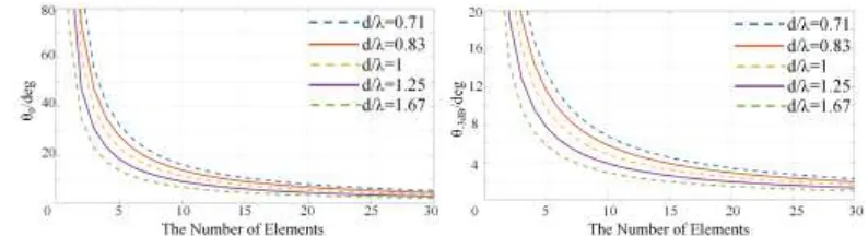
[image:3.595.97.494.476.584.2](11) Fig. 3 and Fig. 4 below show the relationship between Θ0, Θ-3dB and the number of elements when d/λ is different.
Figure 3. The relationship between Θ0 and N. Figure 4. The relationship between Θ-3dB and N.
It can be seen that the sharpness of the main lobe is directly proportional to the d/λ ratio and the number of array elements. However, as the N value continues to increase, the impact on the main lobe begins to slow down. In other words, in the design of the array, it is not necessary to blindly pursue multiple elements in order to improve the directivity.
Variation of Main Lobe Width in Phased Array
) sin (sin sin
) sin (sin sin
) , (
0 0 0
1
d N
Nd
D
(12) Similarly, according to the derivation process in 3.1, we get the formula of the angle of sharpness of the array in the direction of phased array and the half-power point open angle:
) arcsin(sin
)
arcsin(sin 0 0
' 0
Nd Nd
(13)
) 42 . 0 arcsin(sin )
42 . 0
arcsin(sin 0 0
' 3dB
-Nd Nd
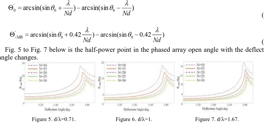
[image:4.595.60.523.175.391.2](14) Fig. 5 to Fig. 7 below is the half-power point in the phased array open angle with the deflection angle changes.
Figure 5. d/λ=0.71. Figure 6. d/λ=1. Figure 7. d/λ=1.67.
As can be seen, the larger the value is, the larger the number of array elements is, the smaller the main lobe width is affected by the deflection angle. That is to say, when the value is larger, the number of array elements is larger, the phased array can maintain the original main lobe sharp degree at the same time get a larger deflection angle.
Do not Appear Grating Lobe Conditions
When the object studied is a non-phased array, we can see from Eq. 9 that when d/λ=1, there is a grating lobe in the first quadrant, but if the last minima between the main lobe and the grating lobe When θN-1=±π/2, the grating lobe will not appear in the range of -π/2~π/2. Therefore, by substituting θN-1 into the minimum equation of Eq.9:
N N
d 1
(15) When the object of study is a phased array, the same can be obtained to eliminate the grating lobe conditions:
2 sin
1
N N
d
(16) From this it can be seen that the phased array has more stringent requirements on eliminating grating lobes.
Simulation
phased array with better directivity in proper deflection range while controlling the manufacturing cost and increasing the production difficulty.
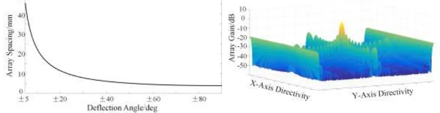
Based on the above analysis and past experience[5,6], we choose the acoustic emission frequency of the array element 45 kHz and the number of array elements 15, and get the maximum of the grating lobes without phase grating in the phased array Element spacing and deflection angle of the relationship, as shown Fig. 8 below.
Can be seen, with the expansion of the deflection angle range, array spacing must be reduced sharply in order to ensure the absence of grating lobes. When the deflection range is about ± 20°, the array element spacing has dropped to 10 mm. If the deflection range is continued, the array element spacing will continue to decrease, which brings difficulties to the actual manufacturing of the equipment. At the same time with the contents of Chapter 3.2, in order to ensure the sharp degree of the main lobe, d can not blindly shrink. So considering, when the phased array ultrasonic transducer array transmit frequency selection 45 kHz, the number of elements is 15, the deflection angle should not exceed ± 20°. Array spacing of 10 mm, half-power open-angle of 3°. This will not only meet the needs of the point, but also reduces the difficulty of making equipment. The Fig. 9 below is a schematic view of the uniform planar phased array that satisfies this condition (15 × 15).
[image:5.595.76.516.299.412.2]Figure 8. The relationship between maximum array spacing and deflection angle.
Figure 9. Uniform Planar Phased Array Pointing Schematic.
Conclusion
In this paper, the effects of array elements such as number of array elements, pitch, frequency and deflection angle on the array directivity are analyzed in detail by formula derivation and simulation. The results show:
① The number of array elements, array spacing and sharpness of the main lobe is proportional to the wavelength inversely proportional to;
② Under realistic conditions, the deflection of the phased deflection can not be too large, otherwise the grating lobe or array element spacing will be too small to be realized and so on.
At the end of this article, we propose a phase-controlled ultrasonic planar transducer array that takes into account both the array performance and the actual manufacturing cost, which provides the basis for the performance evaluation and optimization design of the phased array ultrasonic transducer array.
References
[1]De-ke Li. Principle and Application Research of Acoustic Directional Transmission Syste m Based on Acoustic Parametric Array, D. Cheng Du: University of Electronic Science and Technology of China, 2011.
[2]Zhen-dong Luan, Jin-Duo Zhang, Qian-Ren Wang. Piezoelectric Transducers and Transdu cer Arrays, M. Bei Jing: Peking University Press, 2004: 327-392.
[4]Jian Lin, Jian-Min Ma, Zi-Ting Zhuang. Influence of Transducer Array on Directivity of Acoustic Fields, J. Noise and Vibration Control, 2010, 30(3): 55-59.
[5]Xing-juan Liu. Study on Piezoelectric Infrasonic Phased Array Technology, D. Tai Yuan: North University of China, 2014.