© 2016, IRJET | Impact Factor value: 4.45 | ISO 9001:2008 Certified Journal | Page 2141
COMPARITIVE STUDY ON STURUCTURES HAVING VERTICAL AND
STIFFNESS IRREGULARITIES UNDER WIND LOAD
K.DIVYA S.SAI HARSHA
Student Student
Department of Civil Engineering Department of Civil Engineering Andhra University College of Engineering Andhra University College of Engineering
DR. SHAIK YAJDANI Associate Professor Department of Civil Engineering
---***---Abstract -Urbanization has led to housing problems. This has resulted in the rise of several Multi-storey and High rise buildings. Hence Structural Dynamics study has been steadily increasing over the years. The present
study describes the effect of wind of speed 50 m/sec on 4 buildings of G+10 multi storied framed structure for
different irregularities. The 4 structures considered are Regular building, Stiffness irregular, Vertical irregular,
vertical and stiffness irregular buildings. The results were tabulated by performing analysis using STAAD Pro in
the form of bending moment, shear force, axial force and storey displacements.
KEYWORDS
:
axial force, bending moment, deflection, shear force, Staad pro., stiffness
irregularity, vertical irregularity, wind analysis.
I. INTRODUCTION
Buildings are defined as structures utilized by the people as shelter for living, working or storage. In
21ST century due to huge population the number of areas in units is decreasing day by day. In high rise buildings
we should consider all the forces that act on the building. The beam, column reinforcements and joint detailing
should be good enough to counteract these forces successfully. Wind is a phenomenon of great complexity
because of the many flow situations arising from the interaction of wind with structures.
Wind in general has two main effects on the tall buildings.
1. It exerts forces and moments on the structure and its cladding.
2. It distributes the air in and around the building mainly termed as wind pressure. Sometimes because of
unpredictable nature of wind it takes so devastating form during some wind storms that it can upset the
© 2016, IRJET | Impact Factor value: 4.45 | ISO 9001:2008 Certified Journal | Page 2142
Analytical method given in the code IS 875 part 3-1987 is followed. The analytical method is usually acceptable
for a building with regular shape and size.A structure can be classified as irregular if the structure exceeds the
limits as prescribed by different design codes. Generally multi storey building are of two types.
Regular multi storey building: It has all the loads, mass, stiffness etc., distributed equally along the columns, beams, slab. The chance of collapse of the regular building is less.
Irregular multi storey building: The multi storey building having some structural irregularities like horizontal, vertical, stiffness and mass. The chance of collapse of building is more than a regular building
II. METHOD OF ANALYSIS
Code based procedure for wind analysis:
The basic wind speed for any site shall be obtained from Fig 3.1 and shall be modified to include the following
effects to get design wind speed, Vz at any height, Z for the chosen structure: (a) Risk level, (b) Terrain
roughness and height of structure, (c) Local topography, and (d) Importance factor for the cyclonic region. It can
be mathematically expressed as follows:
V
z = Vb k1 k2 k3 k4. Where,
V
z = design wind speed at any height z in m/s k
1 = probability factor (risk coefficient) k
2 = terrain roughness and height factor k
3 = topography factor
NOTE: The wind speed may be taken as constant up to a height of 10 m. However, pressures for
buildings less than 10m high may be reduced by 20% for stability and design of the framing.
III. MODELLING AND ANALYSIS
An RCC framed structure is basically an assembly of slabs, beams, columns and foundation inter-connected to each other as a unit. The load transfer mechanism in these structures is from slabs to beams, from beams to columns, and then ultimately from columns to the foundation, which in turn passes the load to the soil. In this structural analysis study, we have adopted 4 cases by considering different irregularities for the same structure, as explained below.
1. Regular
2. Stiffness Irregularity 3.Vertical Irregularity
4.Vertical and Stiffness Irregularity
Design characteristic:- The following design characteristic are considered for multi-storey structure
© 2016, IRJET | Impact Factor value: 4.45 | ISO 9001:2008 Certified Journal | Page 2143
TABLE 1 DESIGN DATA OF RCC FRAME STRUCTURES
S.NO PARTICULARS DIMENSION/SIZE/ VALUE
1 MODEL G+10
2 Wind Speed 50m/s
3 FLOOR HEIGHT 3.5 m
4 PLAN SIZE 35.77m x 24.42 m
5 SIZE OF COLUMNS 0.60 x 0.30 m
6 SIZE OF BEAMS 0.45 x 0.3 m
7 WALLS 1) EXTERNAL WALL =0.23 m
2) INTERNAL WALL =0.15 m
8 THICKNESS OF SLAB 125 mm
9 TYPE OF SOIL TYPE-II,MEDIUM SOIL AS PER IS-1893
10 MATERIAL USED CONCRETE M-25 AND REINFORCEMENT
F e-415
11 PLACE VISAKHAPATNAM
© 2016, IRJET | Impact Factor value: 4.45 | ISO 9001:2008 Certified Journal | Page 2144
a) Regular building b) stiffness irregular building
c)Vertical irregular building d) vertical and stiffness irregular building
Fig:- 1 Elevations of the buildings
LOADS CALCULATIONS
Dead load on Floors:
Weight Of The Slab = Thickness of slab x unit weight of RC = 0.125 × 25= 3.625KN/m2
Floor Finish = 1 KN/m2 Partitions = 1 KN/m TOTAL =5.625 KN/m2
Weight Of External Walls (230mm thick) = 3.05 x 0.23x 20 =14.03KN/m Weight Of Internal Walls (150mm thick) = 3.05x 0.15x 20 =9.15KN/m
© 2016, IRJET | Impact Factor value: 4.45 | ISO 9001:2008 Certified Journal | Page 2145
Dead load on Roof:
Weight of the roof slab =0.125 × 25 = 3.625KN/m2 Weight of the water tank = 10KN/m2
Weight of floor finish + partitions = 2KN/m2 Total = 15 KN/m2 LIVE LOAD:
On Roof = 2 KN/m2 internal rooms = 3 KN/m2
Lobby Including Stair Case & Lifts= 4 KN/m2 WIND LOAD
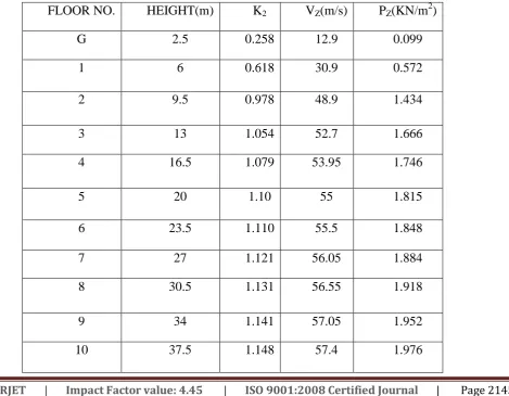
Wind speed Vz=VbK1K2K3
Wind pressure Pz=0.6Vz2
Force coefficients F=CfAepd
where
Vz= design wind speed at any height z in m/s;
K1= probability factor (risk coefficient);
K2= terrain, height and structure size factor;
K3= topography factor;
Pz= design wind pressure in N/m2 at height z;
[image:5.595.83.553.427.792.2]F = force acting in the direction specified
Table 2 Values of K2,Vz, Pz at Respective Floor Height
FLOOR NO. HEIGHT(m) K2 VZ(m/s) PZ(KN/m2)
G 2.5 0.258 12.9 0.099
1 6 0.618 30.9 0.572
2 9.5 0.978 48.9 1.434
3 13 1.054 52.7 1.666
4 16.5 1.079 53.95 1.746
5 20 1.10 55 1.815
6 23.5 1.110 55.5 1.848
7 27 1.121 56.05 1.884
8 30.5 1.131 56.55 1.918
9 34 1.141 57.05 1.952
© 2016, IRJET | Impact Factor value: 4.45 | ISO 9001:2008 Certified Journal | Page 2146
[image:6.595.39.491.72.320.2]a) Wind load on regular building b) wind load on vertical irregular building
Fig 2. Wind load
IV. RESULTS AND GRAPHS
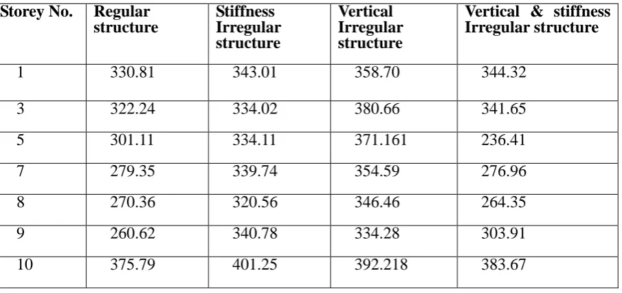
Bending moment:
Table 3 Maximum Bending moment (KN-m) of Beams at different floors
Storey No. Regular structure
Stiffness Irregular structure
Vertical Irregular structure
Vertical & stiffness Irregular structure
1 330.81 343.01 358.70 344.32
3 322.24 334.02 380.66 341.65
5 301.11 334.11 371.161 236.41
7 279.35 339.74 354.59 276.96
8 270.36 320.56 346.46 264.35
9 260.62 340.78 334.28 303.91
[image:6.595.36.489.454.667.2]© 2016, IRJET | Impact Factor value: 4.45 | ISO 9001:2008 Certified Journal | Page 2147
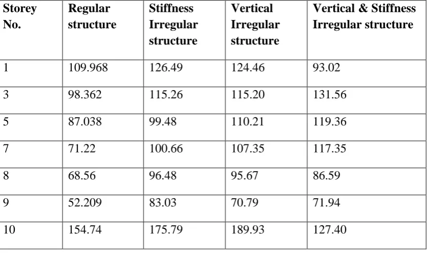
Table 4. Maximum Bending moment (KN-m) of Columns at different floor Shear force
Table 5 Maximum Shear Force (KN) of Beams at different floors Storey No. Regular
structure
Stiffness Irregular structure
Vertical Irregular structure
Vertical & Stiffness Irregular structure
1 206.03 235.05 235.17 267.73
3 168.48 200.69 201.86 236.61
5 145.77 188.57 205.57 239.50
7 130.43 165.66 209.37 244.87
8 126.98 176.36 178.36 264.86
9 146.05 152.31 127.98 236.91
10 229.33 284.21 227.82 265.35
Storey No.
Regular structure
Stiffness Irregular structure
Vertical Irregular structure
Vertical & Stiffness Irregular structure
1 109.968 126.49 124.46 93.02
3 98.362 115.26 115.20 131.56
5 87.038 99.48 110.21 119.36
7 71.22 100.66 107.35 117.35
8 68.56 96.48 95.67 86.59
9 52.209 83.03 70.79 71.94
[image:7.595.91.508.460.707.2]© 2016, IRJET | Impact Factor value: 4.45 | ISO 9001:2008 Certified Journal | Page 2148
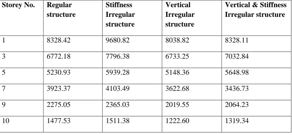
Table 6 Maximum Shear Force (KN) of Columns at different floors Axial force
Table 7 Maximum Axial Force (KN) of Columns at different floors Storey No. Regular
structure
Stiffness Irregular structure
Vertical Irregular structure
Vertical & Stiffness Irregular structure
1 115.64 116.37 124.83 114.57
3 113.38 110.02 130.54 110.29
5 108.76 127.69 127.32 101.02
7 103.74 139.08 123.54 183.7
8 99.68 126.35 128.69 156.46
9 100.093 113.1 116.31 101.79
10 265.30 240.38 237.49 277.25
Storey No. Regular structure
Stiffness Irregular structure
Vertical Irregular structure
Vertical & Stiffness Irregular structure
1 8328.42 9680.82 8038.82 8328.11
3 6772.18 7796.38 6733.25 7032.84
5 5230.93 5939.28 5148.36 5648.98
7 3923.37 4103.49 3622.68 3436.73
9 2275.05 2365.03 2019.55 2064.23
[image:8.595.61.538.435.656.2]© 2016, IRJET | Impact Factor value: 4.45 | ISO 9001:2008 Certified Journal | Page 2149
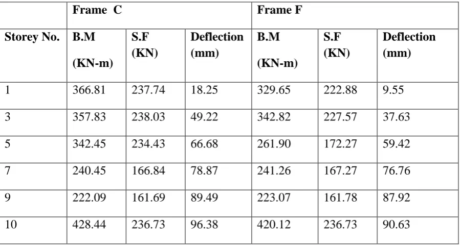
Table 8 Comparison of B.M, S.F, Deflection of Frames in Vertical Irregular Building
V
.
Conclusion
Bending Moment and shear force for structural elements in a structure decreases as height increases in Regular building and Stiffness Irregular building. It decreases in Vertical irregular and Vertical & Stiffness irregular building till the vertical irregularity point and at the floor it increases and then again decreases till top expect last floor due to water tank load.
Displacement of the structural elements increases as the height of structure increases irrespective of the irregularities present.
Axial force of the structural elements decreases as the height of structure increases irrespective of the irregularities present.
When Regular building is compared with other Irregular Buildings the Bending moment and Shear force are less in regular building
When displacement is compared Regular building has more than the other Irregular buildings.
Stiffness Irregular building has more bending forces than without stiffness irregularity building.
The maximum displacement for all structures is observed under the load case 1.2D.L+1.2L.L+1.2W.L(Z).
Frame C Frame F
Storey No. B.M (KN-m)
S.F (KN)
Deflection (mm)
B.M (KN-m)
S.F (KN)
Deflection (mm)
1 366.81 237.74 18.25 329.65 222.88 9.55
3 357.83 238.03 49.22 342.82 227.57 37.63
5 342.45 234.43 66.68 261.90 172.27 59.42
7 240.45 166.84 78.87 241.26 167.27 76.76
9 222.09 161.69 89.49 223.07 161.78 87.92
© 2016, IRJET | Impact Factor value: 4.45 | ISO 9001:2008 Certified Journal | Page 2150 Frames C and F of Vertical Irregular Building when compared the Bending moment, Shear force and
displacement are more for Frame C. means the continuous frame has more forces.
The bending moment and shear force on the floors 1,2 and 3 in structures without vertical irregular has less values than the structures having vertical irregularities values.
VI References
1. ASCE 7-98: Minimum design loads for buildings and other structures, Revision of ANSI/ASCE 7-95, 2000
2. Building planning and design by Kumara swamy
3. Design of steel structures by Subramanian
4. International Journal of Engineering Research & Technology (IJERT)
5. International Journal of u- and e- Service, Science and Technology
6. IS 456 : 2000, Indian standard code for practice of plain and Reinforced concrete design.
7. IS 875 : 1987 (part - 1), (part -2), (part-3) code of practice for design loads (other than earth quake) for buildings and structures
8. Reinforced concrete limit state design by A.K. Jain
9. Text book of concrete technology by S.K.Duggal