Journal of App Published Onlin http://dx.doi.org
Open Access
Mult
Proj
3 Depart
ABSTRAC
This paper co layer. The dep tained and all Pareto-frontie MATLAB.
Keywords: Po U
1. Introduc
Porous piezoc cal imaging, other piezoele tions are refer tures for acou zoelectric mat tivity, extende ing to the acou the developin structures of t On the base o ous materials tion problem structure have tors and comb types of mode transmission. rating sound a In order to e acoustic trans including: low with water, d high mechanic widely used d vices based on their effective
plied Mathemati ne November 20 g/10.4236/jamp.
tiobject
ector w
A. V. N
1Mathema 2
Department tments of Microe
CT
oncerns the op pendences of t owed to decre r calculation h
orous Piezocer nderwater App
ction
ceramic materi ultrasonic tra ectric devices.
rred to the de ustic transduce
terials due to t ed frequency ustic medium. ng of methods the transducers of developed n effective mo statement an e been implem bined devices—
ern devices us A projector is and transmittin effectively ful sducers have w impedance durability; hig cal load and h devices in und n the piezoele e applications c
ics and Physics, 013 (http://www .2013.16017
tive Opt
with Por
Nasedkin1, M atical Modeling t of Electrical En
electronics & M
ptimization pro the effective m ease the numbe has been solved
ramics; Multio plications
ials are widely ansducers, hy
A large numb velopment of ers based on their high piez
bandwidth an The aim of pr for synthesiz s for underwat numerical meth
duli determin nd solving for mented. Hydro
—transceivers sed for sonar s a transducer ng it to the ac lfill its purpo to meet many for better aco gh sensitivity; hydrostatic pre
derwater acous ctric effect. Th caused by both
,2013, 1, 89-94
w.scirp.org/journ
timal D
rous Pie
. S. Shevtsov
Department, So ngineering, Nati Marine Engineeri Email: m
Receiv
oblem for mul moduli for poro
er of design v d using the liv
objective Optim
y used in med ydrophones an ber of investiga
effective stru the porous pi zoelectric sens d better match resented work
ing the optim ter application hod for the po e the optimiza r whole devic ophones, proje
are the gener and underwat r used for gen coustic medium ose, underwate y requirement oustic matchin ability to tak ssure. The mo stics are the d he expansion o h the success o 4
nal/jamp)
Design o
ezocom
va1, J.-C. Liu outhern Federal U
ional Taiwan Oc ing, National Ka mariamarcs@bk. ed October 2013
ltilayered ultra ous piezoelect variables. The ve-link of finite
mization; Pare
di-nd
a- c- e- si- h-is mal ns.
or- a-ce
c-ral
er e-m.
er ts, ng ke ost e- of of
the piez the mic ogies t active h for rece the pro ance m overcom elemen of layer of the w over th ramics. diate la transdu theoreti lectric propert lectric charact lectric thickne for the energy. lectric u other pi
In pr propert
of Unde
posite A
u2, S.-H. Cha University, Ros cean University, aoshiung Marine .ru
3
asonic transdu tric material on
multiobjective e-element (FE)
to Frontier; M
zoelectric mat cro-electromec to create devi hydrophones a eiving and rad oblems at real matching. The u
ming this diff nt made of den rs are needed; whole structur his difficulty is This entails ayers and bett ucer and mediu
ical [4,5] inve ceramics may ties of transdu materials. Po terized by low modulus d31 ess piezoelectr
efficient conv . Therefore, th
ultrasonic tran iezoelectric de revious works ties of piezoel
erwater
Active E
ang3, J.-K. W tov-on-Don, Ru , Zhongzheng, T e University, Ka
cer with activ n porosity hav e optimization ) package Com
Multilayered Ac
erials science chanical system ices based on and projectors, diation of direc izing such str use of interme ficulty. Howe nse piezoelectr and this invo re. The effecti s the use of po
both decrease ter acoustic ag um. Various e estigations show
y significantly ucers and expa orous piezocom wer values of
at almost th ric modulus version of elec he use of porou nsducers, hydr evices is very p s [6,7] it was lectric materia
Acoust
Elemen
Wu3 ussia Taiwan
aoshiung, Taiwa
ve porous piez ve been previo problem base msol Multiphys
coustic Project
and the devel ms (MEMS),
nanoscale m , arrays of tran cted sound [1] ructures is the ediate layers a ever in case o ric ceramics a olves big energ
ive method for orous piezoele ed number of
greement betw experimental [
w, that porous y improve the and the use of mposite mater the transverse e same value
33
d [6,7] res ctrical and me us materials in rophone structu promising toda
investigated als depend on
JAMP
tic
nts
an
oelectric ously ob-ed on the
sics with
tor;
oping of technol-multilayer
nsducers . One of e imped-allows to of active a number gy losses r getting ectric
ce- interme-ween the
2,3] and s piezoe-e dpiezoe-esirpiezoe-ed
f piezoe-rials are e piezoe-es of the sponsible echanical n
piezoe-ures and ay.
for the ceram tric hardness. the full set of
The aim of tion of multil lectric active expressed thro obtained depe ciently decrea underwater ac such layers as tric, backing p
1) we formul electroelastici optimized obj sure level (S and the mean frequency ran riables are: Y layer, protecti damping para layers; porosi investigation to-frontier cal the 6D space are feasible.
The couple the live-link with MATLA about 30% - 4
Figure 1. The acoustic mediu layer, 3—activ 5—protective f
mics of differen Such depende material const f presented rese
layered transdu element which ough the value endencies of ef ase the number
coustic projec s: an acoustic w plate and prote late the coupl ty in axial-sy jectives we int
PL), transmitt n-square value nge from 100 Young’s modu
ive foam laye ameter and sti ity of an activ
we use the a lculation, i.e. of design vari
ed problem is of the FE pa AB. The best r 40% of porosi
scheme of mul um: 1—acoust ve porous piezoe
foam layer.
nt connectivity encies have be tants.
earch is a struc ucer with the h all material’ e of porosity. ffective modul r of design va ctor which str window, match ective foam lay
ed problem o ymmetric form troduce averag ting current r e of the SPL to 400 kHz. ules of an ac er, and matchi ffness dampin ve piezoelectri approach base building the s ables where al
numerically i ackage Comso results have b ity for piezoel
ltilayered trans ic window lay electric layer, 4
y and ferroelec een obtained fo
ctural optimiza porous piezo s parameter ar
The previousl li allow to suff ariables. For th ructure contain hing, piezoelec yers (see Figur f acoustics an mulation. As th ged sound pre response (TCR L irregularity i The design va coustic windo
ing layer; ma ng parameter o
ic layer. In th ed on the Par set of points i ll the objective
mplemented b ol Multiphysic een obtained ectric layer an
sducer placed er, 2—matchin 4—backing plat
c-for
a- e-re ly fi-he ns
c-re
nd he
es-R) in a-w ss of his e-in es
by cs at nd
in ng te,
mechan ers that terials. parame than fo method timizati
2. Dep
Por
For the approac effectiv ative vo use of t obtain compos but an model o cells— pores [2 a skele come th tion the ters can from pi ten-San present ten-San
The with th dium f present thod, m by trian into acc corresp calculat uniform experim
Figu
33 ( S)
r
with the the dep Sander of pola obtaine also can and nu data fro tained i and giv and the
nical and damp t may characte
Electro-acous eter, is signifi r the dense ce ds might be ef ion of enough
pendencies
rosity
e effective pr ch presented i ve moduli meth
olumes for po the FE technol the structure site material. A
adequate mic of the piezocer cubes, some o 2]. However, ton at a large his problem th eory can be us
n be built fro iezoelectric ma nder’s method ted work both nder’s method experimental he obtained res ferroelectric ha ted below, the marked by circ ngles. The dep count the inho pond to dotted tions perform m polarization mental data.
ure 2 shows
33( ) / 33(0
S S
p
e experimental pendencies are methods. The arization field’ ed without this n be seen that umerical result
om [10]. The in [11] strongl ve about 35% d e results from [
ping paramete erize a wide ra stic efficiency
icantly higher eramics. Obtain
ffectively used wide range of
of the Effec
operties deter in details in [6
hods [2,6-8], m orous piezoelec
logies. There a of a two-pha At low percen crostructure of ramic cubic la of which are ra this model ma number of po he algorithms sed. In case of om pores, whi aterial. One of d [9] has been
methods: rand were used.
data [2,4,10 sults for a por
ardness PZT-4 e curves, relate cles, and the W
pendences, ob omogeneity of d lines; dash-d med at taking i
; and the dash
the relative 0) on porosit
l data [10,11]. linear for bot results obtain ’s inhomogene s hypothesis l all four depen ts are in bette
values of ele ly decrease wi discrepancy w [9].
rs of intermed ange of polym , defined by t r for porous ned data and p d for the struct f transducers.
ctive Modul
rmination we 6,7] and based modeling of re ctric materials are several me ase cubic piez nt of porosity a
f porous mate attice consistin andomly declar
ay lose connec ores. In order
based on the f low porosity t
ile at high po f such method n analyzed in dom method a
0-12] were co rous material w 4. For all the ed to the rand Witten-Sander
btained withou f the polarizati dot lines corres
into account t hed lines indi
electric perm ty p in com
One can conc th random and ned with the hy eity differ fro less than 1%
dencies are ve er agreement w ectric permitti ith increasing with the calcula
diate lay-meric ma-the TCR
material proposed tural
op-li on
used an d on the epresent-s and the ethods to oelectric a simple erial is a g of unit red to be ctivity of to over- percola-the clus-orosity—
s is Wit-n [8]. IWit-n
and
Wit-ompared with
me-figures, dom
me-method, ut taking
on field, spond to the non- icate the
mittivity mparison lude that d Witten- ypothesis om those
- 2%. It ery close,
with the ivity
Open Access
Figure 2. The d porosity.
After the ca ( ) E
c p , ei(p
characteristics coefficients d
where sEeff a trix). The com the experimen longitudinal ( piezoelectric m
As can be related to the creases with in method. It is o assuming of better agreem
3(a)). At the s lectric modulu rosity for both that the maxi approximately about 3% - 5%
At the sec during the sim ture, the obta polarization f Witten-Sander properties for
3. Coupled
Electroel
Piezoelec
In presented ultrasound pie cations in its surface and th protective lay
dependency of
alculation the f )
p , iiS ( )p , s of piezoelect
31
d and d33 are the compo mparison of the
ntal data [2,4
Figure 3(a)) a moduli.
seen the dep e Witten-Sand ncreasing poro obvious that th polarization f ment with the same time, the us d33 are es h methods (Fig imum error is y 10% - 15% % for the data [ cond stage of mulation of a m ained dependen
field’s inhomo r method hav
the active elem
Problem o
lasticity for
ctric Transd
investigation, ezoelectric tran
axial-symme he bottom of a yer made of f
relative electric
full set of the e we obtained tric ceramics (di di( )p
onents of the c e obtained dep 4,13] are perfo and transversa
endency for der method, si
osity compared he relationship field’s inhomo e experimenta e dependencies ssentially inde
[image:3.595.62.287.88.243.2]gure 3(b)). It still quite sig for the data [2,4].
the presented multilayer tran ncies at the a ogeneity and ve been accep
ment.
f Acoustics
r a Multilay
ducer
we consider nsducer for un etric formulati
transducer are foam. Transdu
A. V. NAS
c permittivity o
effective modu such importan as piezoelectr
( ) E ( ) i
e p s p
compliance ma pendencies wit ormed for bot al (Figure3(b
31
d coefficien ignificantly d d to the random p obtained at th ogeneity is in al data (Figur
s for the piezo ependent of po
should be note gnificant and
from [13], an
d investigation nsducer’s stru assuming of th
related to th pted as materi
and
yered
a model of a nderwater appl ion. Cylindric e covered with ucer consists o
SEDKIN ET
on
uli nt ric ) , a-th th
b))
nt, e-m he a
re
e- o-ed
is nd
n, c-he he ial
an
li-al h a of
Figure cients o
four lay layer, m constru the bo matche dent up reflect piezoel have be the lon acousti matchin same f coupled the FE plicatio monic quency the inh pressur
where is a sp frequen bounda bounda and axi
1).
AL.
3. The depend n porosity.
yers, such as: matching laye uction is surrou oundary of an ed layer (PML
pon the PML at the interfac lectric layer, p
een chosen to ngitudinal wav c window th ng layer—1/4 frequency of a
d problem of a package COM on modes: Pr
analysis) and y response anal homogeneous H
re p:
0 = 1000 kg/m peed of sound ncy with f
ary conditions ary between a
ial symmetry
dencies of relat
backing plat r and acoustic unded with an
n acoustic m L) is placed so
from a non-P e (Figure1). protective and o be approxim ve at thicknes hickness—app 4 of the longi about 300 kH acoustics and MSOL Multiph ressure Acous
Piezo Axial lysis). Sound w Helmholtz equ
2
0 0
1
p c
m3 is a fluid de d, 2f
Hz denoting are following an acoustic m (on the left b
tive piezoelectr
e, piezoelectri c window. Th n acoustic med medium the p
o that the wav PML medium The thicknesse d backing plat mately a half le
ss vibration m proximately 3 itudinal wave Hz. We formu
electroelastici hysics and its stics mode (t Symmetry mo waves are gove uation for the
2
2 0
s
p
c ,
ensity, cs 15
rad/s is the g the frequen
: sound hard w medium and th
oundary), (see
JAMP 91
ric
coeffi-ic active he whole dium. On perfectly ves, inci-m, do not
es of the te layers ength of mode; an 3/4, and es at the
ulate the ity using
two ap-ime-har- ode
(fre-erned by acoustic
(1)
500 m/s angular ncy. The
wall (the he PML)
The constitutive relations for the piezoelectric active layer are taken in the stress-charge form as follows:
*
E
S
σ c ε e E
D e ε ε E, (2)
where ε is the strain tensor, σ is the stress tensor, E is the electric field vector, D is the electric displace-ment vector; cE is the tensor of elastic stiffness moduli at constant electric field; e is the tensor of piezoelectric moduli (stress coefficients); εS is the tensor of electric permittivity moduli at constant mechanical stress.
Coupling between solid end acoustic media is pro-vided by the boundary conditions: the top and the sides of a transducer undergo both an acoustic pressure and the inward accelerations. The bottom of a transducer is fixed; on the left boundary we consider an axial symmetry con-dition; on the top of piezoelectric layer the constant elec-tric potential with amplitude 100 V in whole studied fre-quency band is applied, when the bottom is grounded.
Since the dimensions of the investigated transducer are quite small, this type of projector cannot be used to gen-erate directional sound and therefore we will consider the sound pressure level only in a direct ray. When the transducer is placed into acoustic medium the thickness vibration mode is excited at frequencies from approx-imately 100 to 400 kHz. This frequency range was used during the following optimization of transducer’s para-meters.
4. Multiobjective Optimization of the
Piezoelectric Transducer
There is a wide range of materials that can be used as the constituent layers of a transducer; this proves the possi-bility to vary their mechanical properties within the wide scope. It should be noted that we chose tungsten as a backing plate material to generate the thickness vibration mode of a PZT layer because of its large mechanical stiffness and high acoustic impedance. In order to for-mulate the optimization problem let us introduce six de-sign variables: porosity of an active layer (por), Young’s modules of an acoustic window layer (Eaw), matching layer (Em ), and protective foam layer (Ef ); mass damping parameter (R1) and stiffness damping parame- ter (R2) of layers. In our investigation we considered three objectives: sound pressure level (SPL) in direct ray measured at the 1m distance from the sound source and transmitting current response (TCR) to be maximized; the deviation of SPL is to be minimized. SPL is repre- sented in decibels as follows
1
20 lg ref
p p p , (3)
where p1 is the sound pressure at the measurement point; and pref 2 105
Pa is the threshold of sound
pressure. TCR is the ratio of an absolute value of sound pressure p1, to the amplitude of electric current I through the active element:
1
I
S p I. (4)
There is a wide range of approaches to structural opti-mization. In the framework of multi-criteria optimization problem (MOO) when several objective functions exist, there is no unique solution, but a number of optimum solutions exist. In this situation the most suitable way to optimization is a calculation of a so-called Pareto opti-mum or Pareto-frontier. Using the Pareto approach we suppose the assignment of a set of choices for all objec-tive components that are Pareto efficient. By confining the set of choices to only the Pareto-efficients instead of considering the full range for each parameter, it is possi-ble to make trade-offs within this set. During the solving of considered optimization problem the three integrals were assumed to be optimized:
2
1
2 1
f
f
p
p f df f f , (5)
21
2
2 1
f
f
p p f df
p
f f
, (6)
2
1
2 1
f
f p f
TCR df f f
I f
, (7)where p , p and TCR represent an averaged SPL, deviation of SPL and TCR, respectively; f1 and
2
f are the boundaries of the frequency range.
Obviously the construction of a Pareto-frontier was complicated for the three-dimensional space of objective functions. In order to overcome this difficulty the illu-stration of a Pareto-frontier has been represented using the level lines. At the numerical problem solving MAT-LAB varies design parameters for the transducer, calls the FE model simulated by Comsol Multiphysics, and is carry out the multiple computations of the objectives. Then obtained data are being analyzed and illustrated using the set of complimentary procedures, written in MATLAB (see Figures 4(a), (b)).
5. Numerical Results and Discussion
Open Access
Figure 4. Proj contour lines o variables.
of matching l side protectiv window. For ing bounds fo
1500 dB/A of SPL. On th and dashed lin the 2D subsp represent the seen from Fig racterized by porosity of ac maximum val variation of p SPL value shi matching laye porosity; on t corresponds t quency respon
jections of the of objectives lev
ayer; Figure 4 ve layer and Y the studied ob r the feasible v – for TCR, an he presented fi
nes are the pro paces of the d intersections
gure4(a) that TCR, reache ctive layer is g lues of SPL a orosity. One c ifts with the gr er from about the other hand to lower poro nse of SPL are
e criteria set p vels on the sub
4(b) for Youn Young’s modu bjectives we u values: 150 nd 2.5 dB f igures the area ojections of Pa design variable of optimum a the energetic es desirable va greater than 0.3 are reached at can observe th rowth of Youn 1.6 GPa till 2. d the lower Yo osity. The mo
e reached when
A. V. NAS
presented as th bspaces of desig
ng’s modulus o ulus of acoust used the follow
dB for the SP for the deviatio as between soli areto frontier o es. Green area areas. It can b efficiency, ch alues when th 3. However, th t a considerab hat the optimum
ng’s modulus o 2 GPa at high oung’s modulu
st uniform fr n the percent o
SEDKIN ET
he gn
of tic w-PL,
on id on as be a-he he le m of er us e-of
porosity that the cantly quency the valu time th window areas.
For c cy resp design
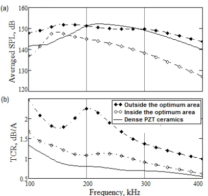
For from th tains p last set made o (Young side the the Pare For ponses the Fig The g optimal uneven cases o porosity level in (1), (2) The so range i base of on 10%
ure 5(b
utmost are take device taining the wh TCR d respons
6. Con
Ten dep
Table 1 lated pr
Stu des
Insid optimu Outsi optimu Dens
AL.
y is greater th e Young’s mo
influences on y response; the
ues greater th he Young’s m w layers does
clarity, we pre ponses obtaine variables that the first set a he obtained op arameters bein t corresponds t of dense piezoe g’s modulus o
e optimum are eto frontier. each set of d
for SPL and
ures 5(a) and graphs shown l set of design nness of sound of active eleme y. The maxim n the investiga ), and (3) are ound pressure s the best. It e f dense cerami %. The peak ob
b)) shows tha resonance pr en from the op
has a sufficien a constant am hole frequency does not worse se for the soun
nclusion
pendencies of
1. Design varia rojectors.
udied sign
aw E ,
GPa de the um area 2.5 ide the um area 0.5 se PZT 0.5
han 0.25. It’s o
odulus of aco n the uniform e optimum qu han or equal to moduli of a pr s not impact
esent below thr d for the three is contained in all the design
ptimum areas. ng outside the to a transduce electric cerami of acoustic win ea, the other fo
design variabl TCR are calc
5(b), respectiv in Figure5, a n parameters d pressure leve ent with dense mum deviation ated frequency 8.5 dB/21 dB
level inside exceeds the SP ics on 5%, and
bserved in the at a transducer roperties when ptimal area. If nt performanc mplitude of th y range, the r en the uniform nd pressure.
f material cons
ables for the th
f E ,
MPa m E ,
GPa
30 16
5 20
30 16
obvious (Figu oustic window ity of the SP uantities corres o 2 GPa. At t rotective and
on TCR in o
ree groups of e sets of value n Table 1.
variables we . The second e Pareto front er with an acti ics; the first pa ndow) was tak our variables b
es the frequen culated and pl
vely.
a clearly shows provides a m el as comparin
ceramics (3) a of the sound y range for the
B/12 dB, resp the whole fr PL of projecto d SPL for desig e TCR graph ( r (1) demonstr n the design v the electronic ce that allows he applied pot resonance fea mity of the fr
tants on poros
hree examples
1 7 10
R
2 7 10
R
1.5 0.6
2.3 1.2
1.5 0.6
JAMP 93
ure 4(b)) w
signifi-PL’s fre-spond to the same acoustic optimum
frequen-es of the
re taken set con-tier. The ive layer arameter ken out-belong to
ncy res-lotted on
s that the much less
ng to the and 20% pressure e designs ectively. requency or on the gn (2)— (see
Fig-rates the variables exciting to main-tential in atures of requency
sity were
of
simu-7 por
0.4
0.2
[image:5.595.310.536.656.736.2]Figure 5. The frequency responses of SPL (a) and TCR (b).
successfully obtained for the porous piezocomposite ma-terials of different connectivity in order to optimize the hydroacoustic performance of multilayered projector based on the active PZT layer with varied porosity. These effective modules were calculated using the FE method at the assumption of homogeneous and inhomo-geneous polarization field. The last dependencies were used at the statement and solving the optimization prob-lem due to the best agreement with the experimental data. Obtained dependencies allowed to reduce the number of design variables to six (porosity of an active layer; Young’s modules of an acoustic window layer, protec-tive and matching layers; mass and stiffness damping parameters of layers). On the base of the Pareto optimal-ity the set of feasible designs in a six dimensional design space was reconstructed using three objectives: averaged sound pressure level, transmitting current response and the standard deviation of the SPL in a frequency range from 100 to 400 kHz. A comparative analysis of three examples of the simulated designs has been performed. It showed the best performance of a projector with porosity near 40% and elastic modules of intermediate layers tuned to achieve the best acoustic impedances matching between the structure and acoustic medium.
7. Acknowledgements
This work is partially supported by the Russian Founda-tion for the Basic Researches (Grant 12-08-31350) and by National Science Council of Taiwan (Project NSC99- 2923-E-022-001-MY3).
REFERENCES
[1] R. Sathishkumar, “Micro Size Ultrasonic Transducer for
Marine Applications,” Indian Journal of Science and Technology, Vol. 4, No. 1, 2010, pp. 8-13.
[2] I. Getman and S. Lopatin, “Theoretical and Experimental Investigation of the Porous PZT Ceramics,” Ferroelec- trics, Vol. 186, 1996, pp. 301-304.
http://dx.doi.org/10.1080/00150199608218088
[3] R. Ramesh, H. Kara and C. R. Bowen, “Finite Element Modelling of Dense and Porous Piezoceramic Disc Hy- drophones,” Ultrasonics, Vol. 43, No. 3, 2005, pp. 173- 181. http://dx.doi.org/10.1016/j.ultras.2004.05.001 [4] A. N. Rybyanets, “Porous Piezoceramics: Theory, Tech-
nology, and Properties,” IEEE Transactions on Ultrason- ics, Ferroelectrics, and Frequency Control, Vol. 58, No. 7, 2011, pp. 1492-1507.
http://dx.doi.org/10.1109/TUFFC.2011.1968
[5] V. Yu. Topolov and C. R. Bowen, “Electromechanical Properties in Composites Based on Ferroelectrics,” Sprin- ger, London, 2009.
[6] A. V. Nasedkin and M. S. Shevtsova, “Improved Finite Element Approaches for Modeling of Porous Piezocom- posite Materials with Different Connectivity,” Ferroelec- trics and Superconductors: Properties and Applications, Nova Science Publishers, Parinov, 2011, pp. 231-254. [7] A. V. Nasedkin and M. S. Shevtsova, “Multiscale Com-
puter Simulation of Piezoelectric Devices with Elements from Porous Piezoceramics,” Physics and Mechanics of New Materials and Their Applications, Nova Science Publishers, Parinov, 2013, pp. 185-202.
[8] L. P. Khoroshun, B. P. Maslov and P. V. Leshchenko, “Prediction of Effective Properties of Piezoactive Com- posite Materials,” Kiev, Nauk Dumka, 1989.
[9] T. A. Witten and L. M. Sander, “Diffusion-Limited Ag- gregation: A Kinetic Critical Phenomenon,” Physical Re- view Letters, Vol. 47, No. 19, 1981, pp. 1400-1403. http://dx.doi.org/10.1103/PhysRevLett.47.1400
[10] R. Guo and C.-A. Wang, “Enhanced Piezoelectric Prop- erty of Porous Lead Zirconate Titanate Ceramics with One Dimensional Ordered Pore Structure,” Journal of Applied Physics, No. 108, 2010, pp. 1-4.
[11] B. Jadidian and A. Winder, “Porous Piezoelectric Ceram- ics with 0 - 3 Connectivity,” 2013.
http://www.jwmed.com/docs.htm
[12] J. F. Li, K. Takagi, M. Ono, W. Pan and R. Watanabe, “Fabrication and Evaluation of Porous Piezoelectric Ce- ramics and Porosity-Graded Piezoelectric Actuators,” Journal of the American Ceramic Society, Vol. 86, No. 7, 2003, pp. 1094-1098.
shttp://dx.doi.org/10.1111/j.1151-2916.2003.tb03430.x [13] A. N. Rybyanets and A. A. Rybyanets, “Ceramic Piezo-