National Power and Energy Conference (PECon) 2003 Proceedings, Bangi, Malaysia 22
Object Oriented Sparse Linear Solver
Component for Power System Analysis
Hazlie Mokhlis, and K
halid Mohamed Nor, Senior Memher, IEEEAhstract--Thls paper describes the develvpment of a sparse linear solver component for solving linear equation In power system analysis. The solver Is developed Into a component by using Object Oriented Programming and Component Based Development methodologies. This component Is then Integrated
with the load flow and fault analysis components as power system analysis software. By developing the solver and the power system analyses Into a different component, the engineering analysis becomes Independent from the sparse linear solver. Therefore, the solver can be replaced with other solver, whlth may be proprietary code, or when better or Improved solver becomes available In future. The replacement will not cause any need to modify the load flow and fault analysls·components. By using Component OilSI'd Development, the software becomes flexible to be updated alad extended.
Keywords--Llnear solver, component, object-oriented Ilower
syslem· model, component-based system devl'lopment, Nomenclature
I. INTRODUCTION
In any to solve matrix equation such as inversion is the core type of power system analyses, a sparse linear solver part of such analysis. Without this solver, power system analys
e
s cantlot be solved. The solver will determine the accuracy of the solution and also the analysis solution time, whether slow or fast. Thus, it is very" important to have a reliable solver, which can solve matrix equation involving various types of large scale sparse matrices in power systemanalysis. The solution time taken in solving matrix equation also needs to be fast especially for realtime application.
For along time, it has been a practice in power system analysis software development to combine the electrical analysis together with the matrix solver such as in load flow application [3, 4]. This approach made the electrical analysis
and
the
solver analysis in the program being coupled together. Modification on particular variable or function may propagate to the whole source codes of both parts, which lead to a massive modification. Due to this problem, software maintenance became difficult, time consuming and costly. This problem can be avoided by developing the solver separately from the engineering analysis before cO"1-bining,them together. In order to develop power system analysis software from different part, an Object Oriented Programming (OOP) and Component based devel
opment(CBD) methodologies can be applied.
This work was supported in part by Ihe University of Malaya, KUDla Lumpur Malaysia, under JRPA grant projett.
Hazlie Mokhlis is with the Department of Electrical Engineering, University of Malaya, (e-mail: [email protected]·llu.Il1Y).
Khalid Mohamed Nor is with the Department of EICCIrical Enginecri"ll. University of Malaya (e.mail: [email protected]).
0-7803-8208-0/03/$17.00 ©2003 IEEE.
By using' OOP, the problem of upgrading can be reduced. There are many reports on the application of OOP for power system application [5-7]. Although OOP has shown 10 help in maintaining software, this is only at Ihe source
codes level
since the codes still have ,10 be recompiled whenever their runclionalities need to be extended. These limitations can be solved by using CBD, where application is built in whole or in part from existing pieces [8]. Component provides many .advantageous to software development such as it allow cross language, simpler to understand and use, and support visual programming. These advantageous have lead to its usage in developing power system analysis such as in [7], where OOP and CBD were both applied. By using CBD, the software became reusable since each of components inside the application is independent between each other. Changing on any component will not affect the rests. The functionality of the component can also be extended wilhout recompiling it.Since the COO methodology pro
vide
s a wily of developing software from various components, power system an<llysis and sparse lincnr solver c<ln be developed into different components. The engineering analysis will be able to use the this solver component to solve linear equation involve in il. However, 10 build from scratch thc solver is time consuming since it involves complex mathematical analysis, which may 1I0t be easy to understand and develop in a short time. Therefore, it is an advantage to lise an existing solver(
source codes) that available in the market or public domain rather than developing it from scratch. This solver can be prepared into a component before integrated itwith power system analysis component to be power system analysis sollwarc.
There are few examples of public domain solvers such as 'SpooJes', 'SuperLU' and 'Boeing'
(I,
2,3].
These solvers have been tested and proven to work in solving various type of sparse matrix. By using such existing solv
er, cost and time of power system software development can be reduced. Furthermore, the electrical analysis will be beller design since the developer can concentrate in the engineering part . and leave the detail of mathematic 10 the mathematicians.In this project, 'SuperLU' is used as
the solver
and has been developed into a component. Although it i§ !I, p.!�blic domain code, it still has the same capabilityCOir.;:;lc''d
to other in solving sparse linear equation. It lIses many latest techniques, such as graph reduction technique in matrix factorization. Furthennore, it can also solve very unsymmetrical matrices. The package comes with real and complex matrices solver, in both single and double precision versions.II.
INTRODUCTION TO SUPERt..U
SuperLU is a general purpose library for the direct solution of large, sparse, non-symmetric systems of linear equations on high performance machines. It was developed by the University of California, through Lawrence Berkeley National Laboratory. It is a license free, which can be used for research with particular conditions. The library is written in ANSI C lind is callable from either C or FORTRAN. Since it is implemented in ANSI C, it need to be compiled with standard ANSI C compilers.
SuperLU contains a set of subroutines libraries for solving sparse linear system of
A-X = B
(I)
where A is a square, nonsingular, n x n sparse matrix and X and B are dense 11 x nrhs matrices, where nrhs is the number of right-hand sides and also the solution vectors. SuperLU provides functionality to solve equation I for both real and complex matrices, in both single and double precision.
Basically, SuperLU uses LU decomposition technique in solving linear equation. The library routines perfonn LU decomposition with partial pivoting. Matrix A is factorized to decompose into Land U matrices as follow,
A . X
= (L . U) . X = B
(2)by first solving for vector y such that
L· Y = B
(3)
and then solving
U· X = Y
(4)
to get the solution of X. Equation 3 and 4 are solved using forward and back substitution. The LU factorization routines can handle non-square matrices of A but the solution for equation 3 and 4 are performed only for square matrices. Matrix A can be in a symmetrical or very unsymmetrical structure.
SuperLU also provides routines to improve backward stability, equilibrate the system, estimate the condition number, calculate the relative backward error, and estimate error bounds for the refined solutions.
III. CLASSES fOR SPARSE LINEAR SOLVER
In this pro
je
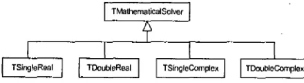
ct, the SuperLU source codes are rewritten into OOp since the original codes are based on ANSI C with a structural programming. There are also some modification in the codes such as changing the maximum number of precision that allowed for a double data type. This is because the library was built under UNIX system, which is different from a PC (Personal computer).The source codes in the SuperLU package are grouped into partiCUlar classes. This grouping is based on the data type of the matrices, whether complex number or real number and also the type of accuracy required for the analysis, whether s.ingle or double precision. The classes and it relationship is shown in Figure 1.
23 Four types of classes that are TSingleReal, TDoubleReal, TSingleComplex, and TDoubleComplex are derived from the base class, which is the TMathemathicalSolver class. This relationship between the base class and derived classes is called inheritance. The base class contains common attributes of data and methods (functions) for the derived classes such as the type of number for data, whether real or complex number. Therefore, the same methods that required in the derived classes do not need to be rewritten again in those classes.
The derived classes are defined with polymorphism relationship with the base class. By doing so, user can access a same method with different operation depending on the defined object, whether single or double precision. Besides the existing functions in the solver, other bask operations such as multiplication and addition involve one-dimensional sparse matrix were also added into this solver classes. As an example fragment of C++ code (header file) for single real solver. is presented as follows,
class PACKAGE TSingleReal : public TMathematicalSolver
{
private: protected: public:
void sCreate_CompCol_Matrix ( .. .); void sCreate_Dense_Matrix ( ...
);
void sCreate_SuperNode_Matrix ( ... );The above header file shows some examples of the methods (functions) inside the Single Real class. These methods have it own task in solving the equation. The
method of sCreate_CompCol_Matrix and
sCreate_Del1se_Matrix for instance are called to set up matrices A and B, respectively, in the data structure internally used by SuperLU. Since the Single Real class is derived from the base class of the Mathematical Solver class, all the data and methods, which was defined as a public or protected type. in the base class can be accessed directly by it. This also applied for other derived classes i.e Double Real, Single Complex and Double Complex. By using classes, the solver becomes reusable that can be extended with other functionility.
IV.
COMPONENT DEVELOPMENT AND INTEGRATION
The discussed mathematical solver classes are packed into a package. In C++ Builder, a package is a special dynamic link library used by C++ application and the Integrated Development Environment (IDE), or both. This package consists of files with the extension type' of BPL, BPI, OB1, and LIB. This package is then installed so as it will be registered in the IDE component palette. The same procedures were applied in developing load flow and fault analysis components. The component palettes are now ready to be used. [image:2.612.85.305.618.678.2]members are taken out. The reason is to hide members that are not accessible in the derived classes from misused.
In order to integrate the components, all the required components need to be installed first. Then, a main program
application is created and all the required functions of the components ate called in the main program. Besides the usual application under DOS environment, the load flow and
fault component also have been successfully integrated with
Graphical User Interface (GU1) components and other component as user-friendly Visual Power System Analysis
Tool software [8]. This tool is built by architecting
componcnt systcms that piny the lItain role in dl'llwing OIlC line diagram, capturing database, and performing analysis
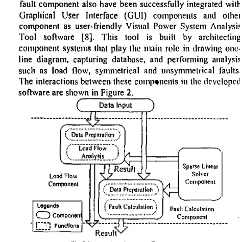
such as load flow, symmetrical and unsymmetrical faults. The interactions between these components in the developed
software are shown in Figure 2.
Lond Flaw
Component
legends
OCompono"
[::1 FunctJc;ms
-Sp.rs<
Un ... SolverComponent
[image:3.612.67.302.136.372.2]Fault C.lcul,tion Component
Fig 2 Interactions between Components
In the above figure, the load flow and fault components
use sparse linear solver component. The functions of the
solver can used to solve equation by calling them in the load flow and fault components. In order to do this, the solver is defined in both component. For fault component, it can receives analysis result from the load flow component such
as the voltage on buses
,
or it can also analyze data directly from the data input.The data for analysis are supplied by user through the data input component. This component could be a database or a group of functions to read text files. In our data input component, user has the choice to provide data by reading text files in the fonnat of IEEE or from database. The supplied data will be processed first in the Data preparation function inside the load flow and fault component. These data will be prepared according to the data structure uses in
load flow and fault analysis. By having these function, load flow and fault analyses components are independent from the structure of the data supplied to it. Thus, any data with different data structure can be supplied as long as it is the right data. The functions can also be considered as an interfac''1..l�er for other application or components to communicate with the load flow and fault components.
The interaction between components shows independency between components. Modification in any of the analysis
components or the solver component inside this application will not affect each other. The solver component call also be replaced with other suitable one without affectillg the load flow and fault analysis components. Therefore, at any time a better solver could be chosen to replace the existing component in the application.
24 By developing application based on components, adding
,
changing or modifying any componenl in the application is possible without affecting other components. Because of this, other data input component based on other data fonnat likes PSSE or other types of' analysis such as stabilityanalysis components can also be integrated into this application. Another important advantage of Ilsing component is that it can be added with other derived classes without need to recompile the existing component. For an example, if we want to create a new function such as to get an inversion matrix, what we need to do is to create a new componcnt
�Ia"
by deriving
it fml\llhe base cluss. Only this component is compiled and not the base class.V. TIlE i\1'1'1.1Ci\TIUN OF MATRIX SOI.VER COMI'ONENl In order to lISC SuperLU
solver, the
involve matrices in load flow and fault analyses need to be prepared according to the matrix storage format use in SuperLU. The storage format is called compressed column format. Basically,
the matrix A in the equation 1 needs to be stored in three different one dimensional arrays. The arrays are referred to asII[], asub[]
and Xlln, which stores the nonzero coefficients of matrix A, their row indices, and the indices indicating the beginning of each column in the coefficient and row index arrays. The total number of the nonzero element of the matrix A also needs to be specified.A. Fault Analysis Application
In fault analysis, matrix inversion is required to get a bus impedance matrix. This matrix is obtained by inversing bus admittance matrix of the power system network. The diagonal elements of the bus impedance matrix, which are the Thevenin impedances of the network is used to calculate the fault current at various buses.
Unfortunately, the SuperLU package does not p
rovid
e aninversion operation since it uses the LU decomposition
technique in solving equation I, which not involving any inversion process. However, we can manipulate the functions provided in SuperLU to develop a function for inversion purpose. Using the LU decomposition provided by
SuperLU and baek substitution routines, it is possible to find the inverse of a matrix column by column. To explain this, consider a linear set of system of equation I with matrix A has dimensional of n x n. The developed inversion function will factorize matrix A once to develop Land U matrices. Matrix B is supplied with a value of 1 in the first row and the rest of the elements are zero. These matrices then are supplied into a SuperLU solving routine to get the
X matrix
. of the equation. The result of this X matrix is the elements of the first column of the inverse of matrix A. The same process is repeated by changing �he value one of matrix B into the second row to get the second column of the inverse matrix A. These processes are continued ulltil all the
columns ofth(l. inverse matrix A are obtained
.
B. Load Flow Application
(6)
whereas for Fast Decoupled (FD) method, it has the same form of equation as in NR but with two decoupled equations
[10]:
(7)
[L\QIV)=
[B"][L\V)(8)
Where,C!P,6.Q
: active and reactive power mismatch vectors /), V,/)' e : voltage magnitude and angle correction vectorsB;�
= 11 Xi�B;�
=Xik I(Rj;
+Xi�)
(9)
B;j=-LIIXik
B;;=-L.B;�+SjkI2
(10)
jEIc jet
(R
and X are the resistance and reactance of transmission line)In order to solve equation 6, 7 and 8 of the NR and FD methods using the sparse linear solver solver component, the Jacobian matrix ofNR and FD methods need to be prepared first according to the SuperLU format. A function called Constrllct structure is developed in both component to prepare the asub[J and
xa[)
arrays, Functions to develop one dimensional arrays forJacobiall[], B'[]
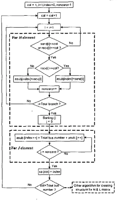
and B"[] are also developed in the load flow component.The process of developing the data structure according to SuperLU format for NR method is shown in the flow chart of Figure 3. The flow chart. shows how data structure for H and J matrices of the Jacobian matrix are determined. The process is starts by setting three variables to their initial value. These variables are col, which represented the column number of matrices Hand J, the index indicates the index number of
asub,
and the nonzero variable indicates for the total number of non-zero elements in the Jacobian matrix. Then, the connections between two busses (send bus and receive bus) are checked whether they are equal to the col value or not. If one of them is equal to the col, the receive bus is then checked whether equal to color not, and then theaSlib
is taken value accordingly as shown in the flow chart and the nonzero value is increased by one. This process is repeated until all the branch data have been checked (i is equal to the total number of branch). After this, a sorting process is done to rearrange theaSllb
array according to the order of row number of the matrix. This is because the connections data between two busses usually not in appropriate order.Y---<.. i:=:Tota1 branch? I
I I I
�---.. --- ---1
I I
I I
I I
I For J elemen t I
I
>-'N"'o---�
II I
�---25
No
c:oI;:;Tolal bus
'---<:...numb@r ')
r---.I Other algorUthm f(){ creat,lng
:
L2t::'�u��_N!.:_���_1
Fig 3 Data structure development in NR method
The next process is to develop the structure of the matrix J. For this the
asub
of the H matrix, which has been found are used. After all theaSllb of
the nonzero element of the J matrix have been found, t�e xa indicates the total number of non zero values in one column of the Jacobian matrix is taken the index value. The process is end when all the col value is equal to the total bus number of the system.For the Nand L matrices, the data structure development is by manipulating all the result obtained from Hand J matrices. Similar process is also taken in developing bus admittance matrix in fault analysis to fulfill the storage format of SuperLU.
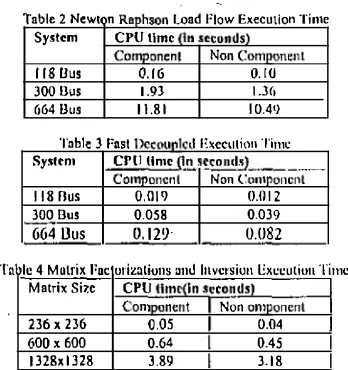
[image:4.612.333.544.42.387.2]Table 2 Newton Raphson Load Flow Execution Time
System CPU time (in seconds) Component Non Component
118 Bus 0.16 0.10
300 Uus 1.93 \.3(, 664 Bus 11.81 10.49
Tn bl e 3 Fasl Decolll'Jco ExeCUlion Timc
System CPU lime (In s!.col1d� ___ ._._�
Componenl Non Component
118 flus 0.01') 0.012
300 Uus 0.058 0.039
664 !Jus 0.129 0.082
Tnbl� 4 Mutrix I'ncturizatiuns �nd hlYcl'siun Exeeutiun Time
M.trix Sile CPU IIme(ln Seconds) Component Non on]lonent
236 x 236 0,05 0.04
600 x 600 0.64 0.45 J328x13Z8 3.89 3.18
All the load flow analysis tests show convergence creteria, which prove the ability of SuperLU in solving matrix equation involving large scale sparse matrices, The execution time of solution is presented in table 2,3 and 4. Its clear that execution time of application based on component
requires more time compared to the non-component. The extra execution time is caused by the overhead given by object oriented classes, where a lot of passing massages are involved, As the number of busses increase, the difference in execution time became smaller. Moreover if the test is run under a more powerful processor, the execution time can be reduced.
VII, CONCLUSION
This paper has presented the application of publ ie domain Source co
d
e, which was del/eloped into a sparse linear solver component. The integration of the component with load flow and fault components has been explained. Although the perfonnance test shows an extra execution time, it not so significant compared with the benefits offered by CBD, Writing more efficient codes or using more powerfulcomputer can reduce the extra time. Since computer processor speed continu
e
s to increase, execution time willnot be a major handicap in using CBD approach.
By developing the power system software based on
component, maintenance is easier as any change in any component does not propagate and affect other components. This development also shows the potential of CBD in developing power system analysis components as off-the shelf products, Power system software developer can therefore maximize time and energy in developing high quality components of his expertise, letting other experts, the. non-power system components developers, develop and
extend functionalities of other components. This will
minimize the cosl of developing and maintaining high quality software.
VIII. ACKNOWLElJOMENT
The authors gratefully acknowledge the assistance rendered
by the Department of Electrical Engineering and the Faculty of Engineering, University of Ma laya in the work reported in this paper,
IX. REFERENCES
[I] "SPOOLES 2.2: Sparse Object Oriented Linear Equations Solver", which i� avail"hle al
hllp:II\\-ww .nell ih,org./hnalg./�r(1oksJsp{\11 h.!;:;�,2. hlml.
26
121 Jmllcs W.lkl1lmcl, J"lmIUiilbcl( mId Xiuoyc S.Li, "SupcrUJ tlscr (,uide", wldch is �vail"ble at
hllp:I/"''''II".lIrr,r,[!.",f,· � ia"yr/Stll'l"11 I!,
IJI
A,F.
Neyer, F.F. W" un" K> hllh".-, "Ohjcct Oticnled I'mllroml11insIbr Flc,ihlc sonwarc: EX:lIl1l'lc or A Loml Flow", IEEE TnmslIctio" 0" I'"wer Sy.lc"", Vut. 5, No. J, A"gu'l 1 '190.
14 j E.i':. ZhllU, "Objcct-oricnlnl I'l1Igr�ll1ll1ing, (' I' lIml I'llwer SY�lcm
Simulation", IEEE Trnn,"ctinll nn Power Systems, Vnl.ll. No, I. hbruUlY 1')%.
151 Il. lIaka'vik, A.Tllolen, "Power Sy'tem MOdeling and Spnrse Matrix
Opcruliulls Usillg Objccl·Oriclltcu 1'1'\Jgl�lllIl,illg", IEEE Tmll. On
Power System, Vol. 9, No.2, May, 1994.
161 Fuley M., Uose A., Mitchell W, unu !'austini A.: "An
Object Based
Graphical User Interface for Power Syslems", IEEE Transactions onPower Systems, Vol. 8, No.
I,
February 1')')1171 Khalid M. Nor, Tnufiq A. Oalli, Hazlie Moknlis, "The Applicalion of Component Based Methodology in Developing Visual I'ower Syslem Analysis Tool", Proceeding of the 22M conference on IEEE I'ES PICA, Sydney, 2000.
{SI Chappel, David, "The Next Wave: Coml'0nent Software Enlers the
Mainstream", White Papers, which is availabte at htlr:(/\\"\\"w.18tional.cmll.
[91 W.F Tinney and CE lIarl,"Power now solution by Newton's method", IEEE Trans. (Power App. Sys). vol. PAS-86, pp.1449-1456, Nov. 1967.
(101 B. Stott and o. Asae, "F.st Oecoupled Load Flow", IEEE Trans.
[image:5.612.108.282.54.239.2]