Numerical Simulation and Flow Behaviors of Taylor Flow in
Co-Axial Rotating Cylinder
Sheng Chung Tzeng
1, *, Tzer Ming Jeng
1, Wei Ping Ma
21
Department of Mechanical Engineering, Chien Kuo Technology University, Changhua 500, Taiwan, ROC.
2 Department of Computer Application Engineering, Lan Yang Institute of Technology, Ilan 261, Taiwan, ROC.
Received 09 July 2013; received in revised form 19 October 2013; accepted 20 December 2013
Abstract
This work uses the incense as the trace of flow to perform flow visualization of Taylor-Couette flow. The
test section was made of a rotational inner cylinder and a stationary outer cylinder. Two modes of inner cylinder
were employed. One had a smooth wall, and the other had an annular ribbed wall. Clear and complete Taylor
vortices were investigated in both smooth and ribbed wall of co-axial rotating cylinder. Besides, a steady-state,
axis-symmetrical numerical model was provided to simulate the present flow field. The Taylor vortices could be
also successfully predicted. However, the assumption of steady-state flow might reduce some flow perturbations,
resulting in an over-predicted critical Taylor number. A transient simulation is suggested to be performed in the
future.
Keyword: Flow visualization, Taylor-Couette flow, Taylor vortices, numerical model
1.
Introduction
Many engineering applications involve rotating machinery components whose basic configurations are usually the
coaxial cylinders with an inner rotating cylinder and outer stationary cylinder. They include rotating membrane filters, rotary
blade coupling of four-wheel-drive vehicle, cylindrical bearings, co-axial rotating heat pipes, rotating extractors, or even
manufacturing and design of semi-conductor units. If the cooling design is poor, overly high temperature will lead to the
deformation, inaccuracy and even damage of the rotating machinery components. To avoid these breakages, the heat must be
removed effectively. Therefore, the issue of heat transfer and fluid flow characteristics in such specific model has attracted
many attentions.
The fluid flow in the annulus of two rotating cylinders was proposed by Taylor [1]. Taylor found that the flow in such
an annulus evolves a series of vortices when the rotational speed exceeds a critical value. Such flow, therefore, is named
Taylor-Couette flow. After the pioneering work by Taylor on the flow stability in the annulus of a co-axial cylindrical
system with an inner rotating cylinder, many scholars showed a keen interest in the study of such rotating flow field, such as
Refs. [2-5].
This work uses the incense as the trace of flow to perform flow visualization of Taylor-Couette flow in both smooth
and ribbed annuluses. Besides, a steady-state, axis-symmetrical numerical model was provided to simulate the present flow
field. The results can be regarded as the base of further study.
*Corresponding author. E-mail address: tsc@ctu.edu.tw
2.
Experimental Apparatus of Flow Visualization
The experimental system presented in Fig. 1 was designed for the flow visualization in a co-axial rotating cylinder.
The apparatus comprised four main parts: 1. rotating system; 2. smoke generator; 3. test section, and 4. image capture system.
The rotating system employed a 5 HP AC induction motor that drove the rotating shaft using a belt pulley system. The rate
of rotation could be adjusted using an inverter to a maximum of 2000 rpm. Rates of rotation of 21, 260, and 442 rpm were
tested. The rate of rotation was measured using a photo-electronic tachometer. The assembly of the rotating system and the
test section was dynamically balanced. The smoke was obtained by burning the joss stick and collected in a box, and then
blown into the test section by the compressor before performing experiments. The test section with a rotational inner
cylinder and a stationary outer housing was made of Plexiglas. The inner cylinder had a length of 240 mm and a diameter of
240 mm. The outer housing was also 240 mm long and had an inner diameter of 268 mm. The inner-cylinder configuration
had two test modes. Mode A involved an inner cylinder with a smooth outer surface. In modes B, 11 annular ribs were
periodically mounted on the surface of the inner cylinder with equalled space (=10 mm). Each annular rib had a width of 10
mm and a height of 6 mm. The image capture system included a 60 mW He-Ne laser light-sheet illumination, a CCD camera
and a computer. After passing through a 5 mm cylindrical glass rod, the laser beam became a light sheet. As the light sheet
illuminated the annular test section, the smoke reflected the laser light and the flow field in the rotating annular channel
could be easily observed. By adjusting the aperture and exposure time properly, one could capture the images of smoke
traces. All data of images were recorded by the computer.
(a)
(b)
3.
Model of Numerical Simulations
3.1. Governing equations and boundary conditions
In order to simplify the present problem, some assumptions were made as follows: (1) the fluid flow is in the steady
state, laminar and incompressible; (2) the properties of the fluid are constant, and (3) the flow field is axial symmetric (i.e.
/=0). The following dimensionless groups are introduced to facilitate the dimensionless transformation of these equations.
r
R
,
z
Z
, i r r r u U , i r u U ,
i z z r u U ,
r
iRe
, Pr , o i o T T T T (1)Besides, the stream function () and vorticity () are introduced.
Z R Ur
1 ,
R R Uz
1 ,
Z U R Uz r
(2)Then the dimensionless governing equations can be obtained as follows.
2 2 2 2 Z R
(3)
} )] ( 1 [ { Re 1 2 ) ( ) ( 2 2 Z R R R R Z U R U Z U R
Ur z
(4)
] ) ( 1 [ Re 1 2 2 2 R U Z U R U R R R R U U Z U U R U U r z r (5) ] ) ( 1 [ Pr Re 1 ) ( 2 2 Z R R R R Z U R
Ur z
(6)
Boundary conditions [6] are as follows. At Z=0 and Z=L/ri,
0 Z U
, 2
2 1 Z R (7)
At R=ri/,
1
U ,0, R R R 1 (8)
At R=ro/,
0
U ,
R R R 1 (9)
3.2. Numerical procedure
The governing equations were discretized according to the power-law scheme proposed by Patankar [7]. All
velocity components Ur and Uz were determined from the stream function. When the velocity components had been
determined, the energy equation was solved to yield the temperature distribution. The solutions were verified by varying the
grid spacing and the convergence criterion. A high density grid node was used near the walls to predict the flow fields
accurately. The number of grid-cells in the flow direction was 1001, and that perpendicular to the flow was 61. The
convergence criterion is
( )
5min ) ( max ) 1 ( )
(n
F
n/
F
n
F
n
1
10
F
Max
(10)
where F is , , U or .
4.
Results and Discussion
4.1. Results of experiments
The present flow visualization focused in an annular channel between co-axial cylinders. The external cylinder was
stationary and the inner cylinder was rotating. For this type of flow field, the fluid was subjected to interactive effects of
Coriolis force, boundary tangential velocity, outward centrifugal force, and fluid viscosity. When the rotational speed of the
inner cylinder was small, the flow field was mainly affected by the boundary tangential velocity and the fluid viscosity, and
the fluid flow was stable Couette flow at that moment, which only had circumferential velocity distribution. The
circumferential velocity field of the stable Couette flow was distributed linearly along radial direction, which could be
regarded as the basic flow field of the co-axial rotating cylinder. When the rotational speed of the inner cylinder exceeded a
critical value, the fluid flow was simultaneously affected by Coriolis force, boundary tangential velocity, outward centrifugal
force, and fluid viscosity, it would generate centrifugal instability. The flow field began to show changes from the two end
sides of the annular channel, and then scrolled toward the central part of the annular channel, thus, to generate numerous
pairs of vortices. This is the famous Taylor vortex.
The measured rotational speeds are used to determine the Taylor numbers (Ta), using
2
3 2
) ]( 2 / ) [(
o i
i
o r r r
r
Ta
(11)
where ro is the radius of the outer cylinder; ri is the radius of the inner cylinder; is the rotational speed of the inner cylinder,
and represents the kinematic viscosity of air in the annulus.
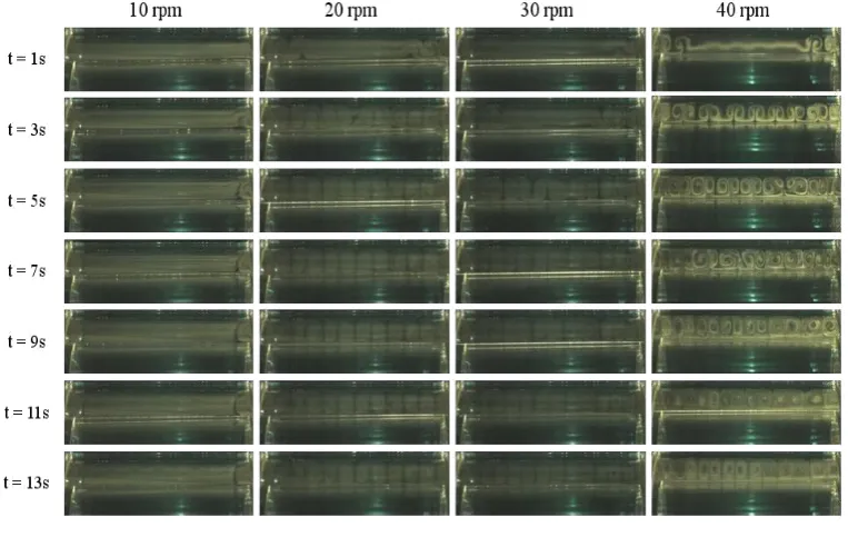
Flow visualizations with various rotating speeds in smooth wall are shown in Fig. 2. Figure 3(a) shows the flow in
Mode A (with smooth wall) at Ta=6583 and t=11 sec after rotating. As shown, it has generated clear and complete Taylor
vortices in the 240mm long test channel. Taylor vortices would generate unstable leftward and rightward fluctuations with
time. Figure 3(b) shows the flow in Mode A (with smooth wall) at the Ta=1009146 and t=1 sec after rotating. Under this
Fig. 2 Flow visualizations with various rotating speeds in smooth wall
(a) Ta=6583 (t=11 sec)
(b) Ta=1009146 (t=1 sec)
Fig. 3 Flow visualizations in mode A (with smooth wall)
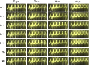
Figure 4 displays the flow visualizations with various rotating speeds in ribbed wall. Figure 5 shows the close-up view
of the flow visualization in Mode B (with ribbed wall) at Ta=6583 and Ta=1009146. As shown, a complete pair of vortex could be formed between adjacent ribs, and the space over the ribs could allow vortices to be formed as well. The flow
visualization of Taylor-Couette flow in both smooth and ribbed annuluses was successful performed. However, the vortices
would became chaos and unidentified when time marched or rotational speed increased (such as 442 rpm). It can be
explained as follows. The flow is laminar at the lower rotational speed, while the transition to turbulence can be possible as
the higher rotational speed with complex geometry being applied. Besides, it also meets the investigations [1–5], which
demonstrated the effects of the centrifugal force and the Coriolis force on the flow characteristics and showed that the
following five dynamical transitions occur in the following order, as the rotational speed is slowly increased; laminar
Fig. 4 Flow visualizations with various rotating speeds in ribbed wall
(a) Ta=6583 (t=9 sec)
(b) Ta=1009146 (t=1 sec)
Fig. 5 Flow visualizations in mode B (with ribbed wall)
4.2. Results of simulation
Figure 6 shows the streamlines in mode A (with smooth wall). The results depicts that the vortices began to occur at
the two end sides of the annular channel as Ta=6583. When Taylor number equals 1009146, 7 pairs of vortices clearly
appeared. The vortices became 10 pairs as Taylor number increased to be 2916431. The present numerical model seems to
successfully predict Taylor vortices. However, the assumption of steady-state flow might reduce some flow perturbations,
resulting in an over-predicted critical Taylor number (Theoretical critical Ta=1708). Figure 7 displays the streamlines in
Mode B (with ribbed wall). As shown, a complete pair of vortex could be found between adjacent ribs, but the vortices did
not obviously occur at the space over the ribs. It may be also attributed to the assumption of steady-state flow. Figures 8 and
9 depicts the isothermal lines in Mode A (with smooth wall) and in Mode B (with ribbed wall), respectively. As shown in
Mode A (with smooth wall), the temperature gradient near wall became sharp when Taylor number increased. However, in
Mode B (with ribbed wall), the contours of temperature had little change with various Taylor numbers. It might be because
International Journal of Engineering and Technology Innovation, vol. 4, no. 2, 2014, pp. 69-76 75
0 2 4 6 8 10 12 14 16
Z 8 10 12 14 16 18 20 22 24 R Ta=6583, Pr=0.7
0 2 4 6 8 10 12 14 16
Z 8 10 12 14 16 18 20 22 24 R Ta=1009146, Pr=0.7
0 2 4 6 8 10 12 14 16
Z 8 10 12 14 16 18 20 22 24 R Ta=2916431, Pr=0.7
Fig. 7 Streamlines for Taylor-Couette flow in mode B (with ribbed wall)
0 2 4 6 8 10 12 14 16
Z 8 10 12 14 16 18 20 22 24
0.07 0.13 0.20 0.27 0.33 0.40 0.47 0.53 0.60 0.67 0.73 0.80 0.87 0.93
R
Ta=6583, Pr=0.7
0 2 4 6 8 10 12 14 16
Z 8 10 12 14 16 18 20 22 24 R Ta=6583, Pr=0.7
0 2 4 6 8 10 12 14 16
Z 8 10 12 14 16 18 20 22 24 R Ta=1009146, Pr=0.7
0 2 4 6 8 10 12 14 16
Z 8 10 12 14 16 18 20 22 24 R Ta=2916431, Pr=0.7
Fig. 8 Isothermal lines for Taylor-Couette flow in mode A (with smooth wall) 0 2 4 6 8 10 12 14 16
Z 8 10 12 14 16 18 20 22 R Ta=6583, Pr=0.7
0 2 4 6 8 10 12 14 16
Z 8 10 12 14 16 18 20 22 24 R Ta=1009146, Pr=0.7
0 2 4 6 8 10 12 14 16
Z 8 10 12 14 16 18 20 22 24 R Ta=2916431, Pr=0.7
76 International Journal of Engineering and Technology Innovation, vol. 4, no. 2, 2014, pp. 69-76
0 2 4 6 8 10 12 14 16
Z
8 10 12 14 16 18 20 22
0.07 0.13 0.20 0.27 0.33 0.40 0.47 0.53 0.60 0.67 0.73 0.80 0.87 0.93
R
Ta=6583, Pr=0.7
0 2 4 6 8 10 12 14 16
Z
8 10 12 14 16 18 20 22 24
R
Ta=6583, Pr=0.7 Ribs
0 2 4 6 8 10 12 14 16
Z
8 10 12 14 16 18 20 22 24
R
Ta=1009146, Pr=0.7 Ribs
0 2 4 6 8 10 12 14 16
Z
8 10 12 14 16 18 20 22 24
R
Ta=2916431, Pr=0.7 Ribs
Fig. 9 Isothermal lines for Taylor-Couette flow in mode B (with ribbed wall)
5. Conclusions
The flow visualization of Taylor-Couette flow in both smooth and ribbed annuluses was successful performed. Besides,
a steady-state, axis-symmetrical numerical model was provided to simulate the present flow field. The Taylor vortices could
be also successfully predicted. However, the assumption of steady-state flow might reduce some flow perturbations,
resulting in an over-predicted critical Taylor number. A transient simulation is suggested to be performed in the future. In
addition, the acceleration of a rotational speed is important. That is, it takes much time to arrive the high rotational speed. It
should be noted in the transient investigation.
References
[1] G. I. Taylor, “Stability of a viscous fluid between two rotating cylinders,” Phil. Trans. Series A, vol. 223, pp. 289-343, 1923.
[2] D. Coles, “Transition in circular Couette flow,” Journal of Fluid Mechanics, vol. 21, pp. 385-425, 1965.
[3] P. R. Fenstermacher, H. L. Swinney, and J. P. Gollub, “Dynamical instability and the transition to chaotic Taylor vortex flow”, Journal of Fluid Mechanics, vol. 94, pp. 103-128, 1979.
[4] R. C. Di Prima and H. L. Swinney, “Instability and transition in flow between concentric rotating cylinders,” in: Swinney, H. L., Gollub, J. P. (Eds.), Hydrodynamic Instabilities and the Transition to Turbulence, Springer-Verlag, Berlin Heidelberg, pp. 139-180, 1981.
[5] G. P. King, Y. Li, W. Lee, H. L. Swinney, and P. S. Marcus, “Wave speeds in wavy Taylor-vortex flow,” Journal of Fluid Mechanics, vol. 141, pp. 365-390, 1984.
[6] P. J. Roache, Computational fluid dynamics. Hermosa, Albuquerque, New Mexico, 1972.
[7] S. V. Patankar, Numerical heat transfer and fluid flow. McGraw Hill-Hemisphere, New York, 1980.