http://www.sciencepublishinggroup.com/j/ijfmts doi: 10.11648/j.ijfmts.20170306.11
ISSN: 2469-8105 (Print); ISSN: 2469-8113 (Online)
Experimental Study on a Line-Axis Concentrating Solar
Energy Collector for Water Heating
Frederick Ikpakwu
1, Anthony Okoronkwo
1, Modestus Okwu
2, Emmanuel Anyanwu
11Department of Mechanical Engineering, Federal University of Technology, Owerri, Nigeria 2
Department of Mechanical Engineering, Federal University of Petroleum Resources, Effurun, Nigeria
Email address:
Ikpakwo_fredrick@yahoo.com (F. Ikpakwu), mechanicalmodestus@yahoo.com (M. Okwu)
To cite this article:
Fredrick Ikpakwu, Anthony Okoronkwo, Modestus Okwu, Emmanuel Anyanwu. Experimental Study on a Line-Axis Concentrating Solar Energy Collector for Water Heating. International Journal of Fluid Mechanics & Thermal Sciences. Vol. 3, No. 6, 2017, pp. 62-69. doi: 10.11648/j.ijfmts.20170306.11
Received: March 29, 2017; Accepted: June 6, 2017; Published: November 28, 2017
Abstract:
This paper examines the experimental study on a line axis concentrating solar energy collector for water heating. The system considered consists of cylindrical solar radiation concentrator with a black coated tubular absorber positioned along its axis. A cold water tank is placed above the collector and a hot water tank positioned below it such that fluid flows in and out of the set up. Solar radiation absorber inlet header is connected to the cold water tank while its outlet header is connected to the hot water tank. These major components are supported by angle iron raised at a distance from the ground that depends on the location and function. Valves are used at strategic points on the connecting pipe lines to isolate the flow of water. When water is poured into the cold water chamber, and the control valve turned on, the water flows under gravity into the receiver/absorber tube. At the absorber section, heat is transferred from the steel tube to the circulating water and is consequently heated. The heated water, then flows into the returning tube against gravity, thereby restricting the heated water from flowing into the storage tank. At this stage, thermo-siphoning effect comes into play. As the temperature of the water increases, its density reduces while the mass remains constant in order to balance the effect of the reduction in density. Thus, there is a resultant increase in volume which consequently pushes the water level further along the returning pipe. Further increase in temperature reduces the water density and increases the volume of the water, thereby causing the heated water to flow into the insulated tank. Several experimental tests were carried out under meteorological condition at the Federal University of Technology Owerri, Nigeria at three different mass flow rates of 0.001kg/s, 0.002kg/s and 0.003kg/s. The solar water heater was tested while oriented in the East–West and North –South directions in order to determine the effects of orientation on the performance. Results obtained showed that a maximum temperature of 69.5°C, corresponding to 34.5°C increase in water temperature and a maximum instantaneous efficiency of 51.01% is possible. The aim of the study is to design a cheaper solar energy system capable of reducing energy bill within the developing countries of the world.Keywords:
Cylindrical Solar Water Heater, Solar Intensity, Mass Flow Rate1. Introduction
Solar energy has been described as the most promising energy of the future [1]. It is the energy transmitted from the sun in form of electromagnetic radiation which requires no medium for its transmission. The earth receives about two hundred billion megawatts (200 x 109 mW) of the total solar output of hundred billion megawatts [2]. This form of energy is finite, abundant, cheap and environmentally friendly. The demand for energy continues to grow by the day. The
International Energy Agency, predicted that the world energy consumption if left unchecked would rise by 53% between 2006 and 2030 with over 70% of the increase coming from the developing countries [3].
estimated that Nigeria receives 5.08 X 10¹² K/Wh of energy per day from the sun, and if solar appliances with 5% efficiency are used to cover 1% of the country’s surface area, then, 2.54 X 10⁶ MWh of electricity will be produced. This huge amount of electricity is equivalent to 4.556 million barrels of oil per day. Thus, solar energy if properly harnessed will in no doubt contribute significantly to the development of Nigeria.
In view of Nigeria’s current shortage in power supply, it is appropriate to design a solar collectors system which will reduce over- dependent on fossil fuel. It is an obvious fact that 80% of the energy utilized in Nigeria is obtained mainly from the fossil fuels with its adverse environmental effect. To address this, it is very appropriate to design systems that will reduce pollution from hazardous gaseous emission. These harmful hazardous gas products pose a great threat to the existence of man on earth. The aim of this study is to design a cheaper solar energy system capable of reducing energy bill within the developing countries of the world.
2. Previous Solar Collector Designs
Several publications are available on solar water heating systems especially on compound parabolic type. Some of the reported works on compound parabolic concentrator (CPC) design include the works of [5], [6], [7]. [5] investigated the performance of new parabolic trough collector hot water storage tank. The storage tank water temperature is increased from 35°C at 9.30h to 73.84°C at 16.00h when no energy is withdrawn from the storage tank. The average beam radiation during the collection period is 699 W/m2. The useful heat gain, the collector instantaneous efficiency, the energy gained by the storage tank water and the efficiency of the system as a whole are found to follow the variation of incident beam radiation as these parameters are strongly influenced by the incident beam radiation. The value of each of those parameters is observed to be maximum around noon at which the incident beam radiation is maximum. Another integrated solar water heater was designed and constructed by [6]. The test unit has an absorber area of 1.3 m2 and a capacity of 178 liters. During the experimental test, they extracted 100 liters of water with peak temperature ranging between 45°C to 50°C. Day time collector efficiency of 60% and overall efficiency of 40% were computed for the system. They found out that night radiation losses were reduced by screen insulation. Similarly, [7] presented results on a simple low cost integrated collector storage solar water heater. The system takes the form of a rectangular shaped tank incorporating the solar collector and storage tank into a single unit. Experimental and numerical study on the integral system was undertaken in order to compare the results with a newly developed macro model. Numerical results obtained were found to be in close agreement with the experimental data.
[8] reported an experimental study on the performance of a compound parabolic collector thermo syphon solar water heater at the Federal University of Technology, Owerri. The result of the experiment gave a temperature of 65°C and
collector efficiency of about 51%. However, their work did not evaluate the effect of mass flow rate and orientation on the performance of the system designed. Similarly, [9] reported a simulation on the performance of a thermo siphon solar water heater. The system consists of flat plate absorber area of 3.0m2. A total heat gain of 63.36MJ was recorded while 50.86MJ was absorbed and only 37.35MJ came out as useful heat giving collector efficiency of 56.51%. It was concluded that simulation work has shown that with a good design configuration of solar water heating system, a reasonable amount of energy can be collected for heating purpose. Similar designs have been reported by several authors like [10], [11]; under meteorological condition of Nigeria. [12] researched on the experimental behavior of a solar water heating system combined with floating covers and photovoltaic cells by using two similar ponds for holding water, one was heated with coil containing an enclosed circulating fluid and the other unheated. To minimize water evaporation the exposed surfaces of the two ponds were covered by floating elements with photovoltaic cells on top to supply energy for water pumping and to power auxiliary devices of the system. The daily average water temperature values was estimated using experimental meteorological data over eight months. The pond with floating covers water evaporation reduction was greater than 90% with respect to an uncovered pond. Also the photovoltaic cells placed on the floating cover generated up to 68 Wp/m2 equivalent to electric power. [13] used Monte Carlo analysis to estimate the techno-economic benefits and reliabilities of solar water heaters. The study focuses on a product range manufactured by a local company in Australia, using the historical data provided by the company The results show that solar water heaters can offer significantly better long-term economic viability compared to conventional systems at moderate auxiliary energy consumptions. [14] reported the basic components of solar water heating system (SWHS) and their advancements. Also, [15] conducted an experimental investigation of an evacuated tube solar air collector coupled to a latent thermal energy and water was used as the working fluid transferring solar gain to the air being heated. The maximum measured temperature differential between the heated air and the ambient air was 37°C and 20.2°C during conditions of incident and non-incident solar radiation, respectively. This occurred using a circular fin configuration at a flow rate of 0.018 kg s−1. The efficiency at low (0.018 kg s−1) air flow rates was 0.05–0.50 times less as compared to high (0.035 kg s−1) air flow rates. This system has advantages over systems using sensible storage as it can be used after sunset due to better heat storing capacity of the PCM. Similarly, Kumar and Yadav (2016) conducted a research by investigating experimentally air heating system using solar collector with evacuated tube incorporated with heat exchangers. However, several publications are available on CPC collector. This paper takes into cognizance the effects of orientation and mass flow rate of fluid on the system
System Configuration
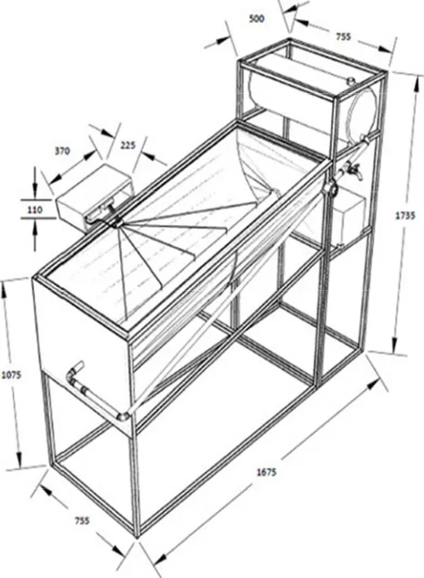
configuration of the cylindrical parabolic concentrating solar water heater. While Figure 2 shows the pictorial views of the system. The system investigated is consists of cylindrical solar radiation concentrator with a black coated tubular absorber positioned along its axis, a cold water tank positioned above the collector and a hot water tank below it such that fluid flows into and out of them by gravity. The solar radiation absorber inlet header is connected to the cold water tank while its outlet header is connected to the hot water tank. These major components are supported by angle iron raised at a distance from the ground that depends on the location and function. Valves are used at strategic points on the connecting pipe lines to isolate the flow of water.
Figure 1. Sketch diagram of Cylindrical Solar Water Heater.
Figure 2. Pictorial view of experimental set-up.
The CPC has a compound parabolic reflecting surface whose line focuses on a cylindrical steel receiver/absorber. The receiver is used to receive incident radiant energy and is
covered with a selective surface of high solar absorptance (αr) and low emittance (εr), whilst the reflector is highly reflective aluminum folded into cylindrical shape. The absorber pipe is made of a steel tube painted black with inner and outer diameters of 9.5mm and 12.7mm respectively. The location of the absorber is at the focal point of the CPC collector. This is to facilitate the heat transfer between incident solar radiation and the absorber material. To further enhance the heat transfer from the concentrated ray to the receiver, the receiver was covered with a thick black coating which is insulated at the edges to minimize heat conduction to the receiver and the reflector. The Water used as heat transfer medium flows through the receiver tube and the tank. To suppress convection losses from the receiver a glass envelope is placed around it. A transparent cover is fitted to protect the reflector surface from deterioration; and also it reduces the rates of heat loss from the receiver envelope configuration. On the other hand to reduce heat losses to the ambient the underside of the reflector is covered with an insulator.
The present system operation is very simple, when water is poured into the cold water chamber, and the control valve turned on, the water flows under gravity into the receiver/absorber tube. At the absorber section, heat is transferred from the steel tube to the circulating water and is consequently heated. The heated water, then flows into the returning tube against gravity, thereby restricting the heated water from flowing into the storage tank. In this section the thermo-syphoning effect comes into play. As the temperature of the water increases, its density reduces while the mass remains constant in order to balance the effect of the reduction in density; thus, there is a resultant increase in volume which consequently pushes the water level further along the returning pipe. Further increase in temperature reduces the water density and increases the volume of the water, thereby causing the heated water to flow into the insulated tank.
At the beginning of the experiment, the valve at the outlet end of the cold water reservoir was opened to allow water flow into the steel pipe and consequently, the initial water temperature was measured and the second valve at the inlet of the hot water tank was shut to allow the water in the absorber tube to heat for about 30 minutes. The readings at the five thermocouple points were taken at the end of the 30 minutes before which the inlet valve at the hot water tank was opened and the temperature of the hot water tank was measured andrecorded.
This exercise was repeated at 30 minutes intervals starting from 8:00 am to 5 pm on daily basis. The atmospheric temperature and the solar radiation were also recorded at each interval of 30 minutes before the temperature of the solar heated water was taken. The Solar Water heater is made of a transparent glass-cover material which houses a stainless steel tube (receiver). The cylindrical parabolic concentrator is sealed at both ends with 2mm mild steel plate in other to allow maximum possible solar radiation that will reach the stainless steel tube which serves as the absorber.
spaced equally along the length of the stainless steel tube. The transparent glass-cover serves the same purpose as glazing in conventional solar water collector. It choice as a glazing material is its ability to transmit maximum possible solar radiation; it also reduces heat loss by convention and radiation, there by acting as a heat trap. It is cheap, availability and transparent. Figure 1 shows the picture of the solar water heater. The complete view of the experimental rig set-up is shown in Figure 2. It consist of a 40 liters mild steel cold water tank insulated with fiber glass and wrapped in aluminum foil to reduce heat transfer into the cold water content of the tank from the ambient air. The tank which serves as the cold water tank was placed on a 1 inch pipe square cross –sectioned stand 1.735m height in order to create enough head to achieve water flow from the cold water tank through the solar water heater. The tank which serves as the hot water tank was placed below the cold water tank. Water flows from the cold water tank through the absorber pipe under gravity but enters into the hot water tank through thermo syphon effect.
Three manual valves were installed: Two to the tanks and one to the water supply pipe. A wedge gate valve (first valve) at the outlet end of the cold water reservoir, and a parallel gate valve (second valve), outlet valve on the cold water supply pipe and allow water to run at required flow rate into the absorber tube. Another, wedge gate value (third valve) is located at the right hand side of the storage tank below the cold water tank, the storage tank below the cold water tank. The supply pipe was insulated using fiber glass and wrapped with aluminum foil to ensure relatively constant water temperature between the cold water tank and inlet of the solar water heater.
3. Experimental Observation
Data were collected at intervals of 30 mins. The most important parameters measured are the ambient temperature, temperature of the cold water storage tank, water temperature variation along the length of the stainless steel tube, the temperature of hot water storage tank and solar intensity. K-type thermocouple insulated with Teflon and metal gauze wire with maximum insulation temperature of 260°C was used. The probe accuracy of the thermocouple is ± 2.2°C or +0.7.5% of reading from 0°C to 800°C. Two types of thermometers were used for measuring temperature, the Patos 305 digital thermometer which has a temperature measurement range of minus 50°C to plus 1300°C and a high resolution of 0.1°C was used to measure the ambient temperature, temperature of cold and hot water storage tank. While the other type of thermometer was a temperature monitoring device system which has temperature measurement ranges of 0°C to 390°C. This system was used to measure temperature variation along the length of the stainless steel tube as the five thermocouple installed to the length of the stainless steel tube were connected to five of the temperature monitoring device systems at the same time throughout the day. The Temperature was measured by simply switching from one input to the other, which made the
time interval after taking temperature reading along the length of the stainless steel tube very small, thus reducing error. The Daystar solar meter which uses a polycrystalline silicon PV cell as sensor was used to measure solar intensity. It provides an accurate reading of 3% from 0.0 to 1200 watts and has a resolution of 1 W/m2.
4. Results And Discussion
Series of performance testing of the cylindrical solar water heater were carried out from 11th January, to 13th February 2013 under meteorological condition at the Federal University of Technology Owerri. It was operated on three different mass flow rates of 0.001kg/s, 0.002 kg/s and 0.003kg/s respectively; In order to ascertain it performance when operated at these mass flow rates. This was done while the solar water heater was orientated in two different directions, the East-west and north-south directions. The cylindrical solar water heater was operated on the design mass flow rate of 0.002kg/s from 11th – 13th and 17th – 22nd January while orientated in the east-west direction respectively. From 23rd-25th January and 1st, 4th and 5th February, it was orientated north-south direction and east-west direction respectively and was operated at a mass flow rate of 0.003kg/s. Finally, at a mass flow rate of 0.001kgs, it was orientated in the east-west direction and north-south direction, respectively on the -8th and 11th, 12th and 13th February, 2013. Seven temperature data points were measured and recorded accordingly.
Table 1 is the design specification of the system. The values were obtained from design calculations using the governing equations. Results obtained from the measurements are presented in figures 3 - 10. These results present similar pattern showing a rise and fall in the water temperature as the insolation changes.
Table 1. Design Specification of the System.
Design Specification
Glazing Material Transparent Glass
Thickness of Glazing Material 0.004m
Length Of Glazing Material 1.98m
Absorber Tube Steel
Outer Diameter of Tube 0.0127m
Length of Tube 1.98m
Tilt Angle 0.99°
Rim Angle 45°
Overall Heat Transfer Coefficient 0.7541w/M2k
Concentration Ratio 1.98
Reflecting Material Aluminum Sheet
Figure 3. Measured solar insolations from 11th January to 18th January 2013.
Figure 4. Experimental result on 11th, 14th and 15th Jan., 2013 at 0.002kg /s east – west orientations.
Figure 4 shows the temperature variation with time of the day for the mass flow rate of 0.02kg/s at north-south orientation. Similarly, it can be seen from figure 4 that the same trend as observed in figure 3 is repeated. it was also noted that the temperature distributions along the absorber tube followed the same pattern irrespective of the fact that it was carried out on a different day.
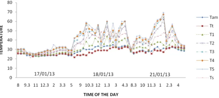
Figure 5. Experimental result on 17th, 18thand 21th Jan., 2013 at 0.002kg /s north –south orientations.
Figure 6. Experimental result on 23rd, 24thand 25th Jan., 2013 at 0.003kg /s north –south orientations.
Figure 7. Experimental result on 1st, 4th and 5th Feb., 2013 at 0.003kg /s east – west orientations.
Figure 8. Experimental result on 7th, 8th and 11thFebruary, 2013 at 0.001kg /s east – west orientations.
Figure 6 presented the poorest performance recorded during the experimental period. Thus, could be attributed to heavily overcast weather condition observed for the day (17/01/2013). The solar intensity recorded during this day was very low, the minimum value being 23W/m2. On this particular day it rained, leading to a maximum out let water temperature of 33°C which corresponds to a water temperature increase of 6.5°C. When a high insolation level at 1027W/m2 was recorded, a maximum outlet water temperature of 69.5°C, corresponding to a 34.5°C increase in water temperature was achieved. This is shown in figure 5. This is an expected trend since high insolation level brings about an increase in energy input into the water. As a result of this, the energy input into the water becomes directly proportional to water temperature. The experimental data presented in these figures 4-9 show constant rise and fall in water temperature as water flows through the solar water heater during the days test were carried out. This same water temperature fluctuation is observed for the solar intensity during the experimentation period. Thus, the behavior of the solar water heater as the insulation level changes reveals that the solar water heater responds quite fast to changing solar
intensity. For instance comparing the temperature and solar insolation profile on Figures 3 and 4. between the hours of 8 am-10:30 am the solar intensity was low and the corresponding exit water temperature was 35°C.
When the solar intensity increased to 180W/m2, within 30 mins, exit water temperature rose to 39°C. A close look at Figures 4 – 9, reveals similar trend in temperature and solar intensity profiles. The cylindrical solar water heater was operated on different mass flow rate of 0.002 kg/s a maximum outlet water of 69.5°C was obtained at a solar intensity of 1027W/m2 on 21/01/2013..
Collector Efficiency
The collector efficiency is parameter used to compare the performance of various collector types. It can either be overall or hourly. The hourly efficiency is reported by [18] as in Eq. 1.
/ .
Q A I
η
=Equation 1 was applied to the experimental data collected for the purpose of analysis. Results of the analysis are presented in Figures 10 and 11.
Figure 10. Efficiency against time.
Figure 11. Efficiency against time.
The solar radiation data used in this analysis is presented in figure 3. It was observed that on days when poor solar
these days. (See Figure 10 and figure 11) while on clear days with high solar intensity the efficiency was high. The best efficiencies obtained were 44.9% (Figure 10) on 21/01/2013, when a mass flow rate of 0.002 kg/s was used, and 51.10% figure 11 at a mass flow rate of 0.003kg/s on 4/02/2013. Thus, best efficiency was recorded at a mass flow rate of 0.003kg/s which ranged between 10-51% with those for overcast days generally not exceeding 35%.
5. Conclusions
Arising from the foregoing results of the test carried out, the conclusion of the study therefore is:
i. the cylindrical solar water heater performed satisfactorily, and is capable of generating hot water at 69.5°C. However, the maximum achievable temperature is dependent on solar intensity and mass flow rate, with operation at a low mass flow rate capable of yielding the hottest water;
ii. the efficiency of the solar water heater ranged from 12.13% to 51.10%, with the best efficiency of 51% occurring at a mass flow rate of 0.003kg/s;
iii. the cylindrical solar water heater responds to change in weather condition and functions more effectively on a sunny weather;
iv. the performance of the solar water heater does not vary when positioned at different orientations due to its cylindrical parabolic shape which allows maximum possible concentration of solar radiation to reach the absorber tube from all directions.
References
[1] Lunder P. J. (1980): Solar thermal Engineering, space heating and Hot water system. John Wiley and Sons in. NY.
[2] Anderson B. and Michael R. (1983): the solar Home Book Chesire Books, Harrisville NH. USA.
[3] IEA (2006), Angola: Towards an Energy Strategy, OECD/IEA, Paris.
[4] Sambo A. S. (2005). “Renewable Energy for Rural Development: The Nigerian Perspective.” ISESCO Science and Technology Vision 1(May, 2005): 12-22.
[5] Arasu A. V. and Sornakumer S. T(2006)., Performance characteristics of solar parabolic Trouhg collector Hot Water Generation System. Thermal science year 2006, volume 10, issue 2, pages (167-174).
[6] Dharuman, C.; Arakeri, J. H.; Srinivasan, K. (2006) Performance evaluation of an integrated solar water heater as
an option for building energy conservation Energy and Buildings, 38 (3). pp. 214-219. ISSN 0378-7788.
[7] Cuurie, J. I, Garnier C., Muneer T., grassie T. and Henderson D. (2008): Modeling Bulk Water Temperature Integrated Collector Storage System. Building Services Engineering Research and Technology 29(3): 203-218.
[8] Okoronkwo. (2014) Experimental study on the performance of a compound parabolic collector thermo syphon solar water heater’ Project Conducted at the Federal University of Technology, Owerri, Imo State, Nigeria.
[9] Adeyemo S. B. (2000): Simulation of the Performance of Solar Energy for Domestic Heating. Global Journal of Mechanical Engineering 3: 14 – 23.
[10] Agbo S. N. and G. O. Unachukwu (2007): Design and performance feature of a Domestic thermosyphonsolar water for an Average-Size family in Nuskka. Trends in Applied Sciences Research 2(3): 224-230.
[11] Egbo G. I (2004): Simulation and validation of the Thermal performance of a solar parabokic – trough concentrating collector in Bauchi, PhD thesis, Abubakar Tafawa Balewa University, Bauchi.
[12] Taboada, M. E., Caceres L., Graber, T. A., Cabeza L. F., Rojas R. (2017) Solar water heating system and photovoltaic floating cover to reduce evaporation: Experimental results and modeling, Journal of Renewable Energy Volume 105 (1-798). [13] Resvani S., Bahri P. A., Urmee T., G. F. Baverstock (2017).
Techno-economic and reliability assessment of solar water heaters in Australia based on Monte Carlo analysis. Journal of Renewable Energy 105 (774-785).
[14] Gautam A., Chamoli S., Kumar A., Singh S. (2016) A review on technical improvements, economic feasibility and world scenario of solar water heating system. Renewable and Sustainable Energy Reviews. 68 (541–562).
[15] Mehla N., Avadhesh Yadav. (2016) Experimental investigation of a desiccant dehumidifier based on evacuated tube solar collector with a PCM storage unit. Drying Technology 1-16. [16] Amit Kumar, Avadhesh Yadav. (2017) Experimental
investigation of an air heating system using different types of heat exchangers incorporated with an evacuated tube solar collector. Environmental Progress & Sustainable Energy 36: 1, pages 232-247.
[17] Hallstrom O. (2016) Design Optimization of a Sorption Integrated Sydney Type Vacumm Tube Collector. ASME. Journal of Solar Energy. 139(2).