http://www.sciencepublishinggroup.com/j/ogce doi: 10.11648/j.ogce.20200801.11
ISSN: 2376-7669 (Print); ISSN: 2376-7677(Online)
Evaluation of Wave Characteristics in Annular Flow in
Horizontal Pipes
Osokogwu Uche
School of Energy, Environment and Agrifood, Cranfield University, Bedfordshire, UK
Email address:
To cite this article:
Osokogwu Uche. Evaluation of Wave Characteristics in Annular Flow in Horizontal Pipes. International Journal of Oil, Gas and Coal Engineering. Vol. 8, No. 1, 2020, pp. 1-9. doi: 10.11648/j.ogce.20200801.11
Received: November 9, 2019; Accepted: December 2, 2019; Published: January 10, 2020
Abstract:
Annular flow experiments in horizontal flow in pipes were conducted with emphasis on wave characteristics (wave velocity, wave frequency) and liquid film thickness. The experiments were conducted using water/air in a 0.0504m pipe diameter with a total flow loop length of 28.68m. Liquid film thickness in all the flow matrix in this study, were observed to be decreasing with increase in gas velocity while increasing with increase in liquid velocity. The decreasing tendency with superficial gas velocity was because of liquid entrainments which were accounted. Pan and Hanratty correlation for liquid entrainment was chosen because it gave the most realistic results among other correlations from the experimental data. Wave velocity and wave frequency were presented to be increasing with increase in superficial gas velocity in annular flow. For wave frequency, it was observed that both superficial liquid and gas velocities have great impact on it. In annular flow in horizontal pipe, it was also observed that the lower the superficial liquid velocity, the lower the amplitude and the higher the wave frequency. This indicates that at low liquid velocity, more ripple waves occurred and at this time more energy were dissipated which resulted to the high frequency observed in this study. However, several correlations where compared with the obtained wave frequency in this study, but [2] preferably matched better as the superficial liquid velocity increases from 0.0903m/s to 0.1851m/s.Keywords:
Annular Flow, Horizontal Pipe, Wave Velocity, Frequency, Film Thickness1. Introduction
Annular flow is a complex flow regime, encountered in petroleum production systems, nuclear power plants, chemical and refining processes (reactors, heat exchangers). Annular flow in horizontal pipes, flow with high gas velocity at the core center of the pipe with much impact of gravity leaving the circumferential liquid film at the internal walls of the pipe which drains to the bottom of the pipe. Annular flow, represents a thick liquid film at the bottom that moves slowly on the internal pipe walls than the gas phase [13]. It is also characterized by asymmetry distributions, depending on the mass flow rate of the liquid and gas [27].
In evaluating annular flow behaviors in pipes: annular flow characteristics like liquid film thickness, wave characteristics (wave velocity, wave frequency), interfacial friction factor and pressure gradient were investigated.
On film thickness, there are several scholarly reports on liquid film thickness investigated in annular flow. [3]
Presented film thickness at the upper part of the walls of the pipe, while [5] conducted experiments on film thickness with respect to axial flow. Also, [6, 29, 15, 24] presented their results on film thickness.
Through experiments, liquid film thickness in annular flow could be determined using these methods:
1. Optical method: e.g. pin, high speed cameras/Laser for detecting interface, etc.
2.Electrical method: capacitance, conductance method (flush-mounted, parallel-wire)
3.Acoustic method: e.g. ultrasonic in which the reflected signals of time interval emitted from gas-liquid interface are converted to film thickness.
4.Radiological method: e.g. X-ray, neutrons and gamma-ray. The different attenuations are used to measure liquid film thickness.
result analysis and method of installation (intrusive or non-intrusively mounted).
1.1. Wave Characteristics in Annular Flow
Wave characteristics could be grouped into: wave velocity and wave frequency in annular flow. However, wave is an oscillation with a transfer of energy that travels through a medium, while frequency is the time-dependent for wave transfer. In annular flow, a non-uniform liquid-film thickness exists circumferentially across the pipes. This liquid film thickness, exhibits an interfacial wave behaviour due to high superficial gas velocities and low liquid velocities attributed to annular flow in pipes. More so, the interfacial wave behaviour reveals, a wavy structure that could be grouped into: ripple and disturbance waves.
1.1.1. Ripple Waves
They are low amplitude and high frequency waves that contribute to the interfacial shear stress in the pipes, [14]. Also, they are characterized by low velocity, short-life time and non-coherent wave that creates interfacial roughness and promote pressure drop in annular flow, [27].
1.1.2. Disturbance Waves
The wave travels with higher velocities, higher film thickness, higher amplitude, and longer-life time, which are responsible for liquid entrainment in the gas core, [27]. The disturbance wave forms a complete ring structures in the pipe.
1.2. Wave Frequency Correlation
Wave frequency in multiphase flow, is obtained from a
corresponding frequency of the largest peak of the “power
spectral density” (PSD) function. In annular flow, several investigations exist to show the effects of superficial liquid and gas velocities on wave frequency. Among these are: [8, 12, 23, 20, 26, 28] who reported that increase in superficial gas velocity, increases wave frequency in annular flow in horizontal pipes. [28] Further presented, that wave frequency decreases with increase in the pipe internal diameter and lastly, that superficial liquid velocity has negligible effect on wave frequency.
Apart from power spectral density in determining wave frequency, there are correlations like: [20] correlation, was also part of the experimental works carried out while developing the wave frequency correlation. However, the same flow conditions and pipe internal diameters used in wave velocity correlation exists in the wave frequency correlation which is expressed as:
= 0.066 . (1)
[26] Developed correlation for wave frequency was based on the experiments conducted with pipe internal diameters of 8.8mm and 15.1mm.
= 0.005 √ (2)
Also, a second wave frequency correlation was developed based on the subsequent experiments, conducted with a pipe internal diameter of 26.3mm.
= 0.035 √ (3)
Experiments on liquid entrainment from gas-liquid flow in 2-inch horizontal pipe with an internal diameter of 0.0486mm and 6-inch pipe also were conducted by [16]. Based on his investigations, liquid entrainment correlation and wave frequency correlation were proposed. On wave frequency, he used Strouhal number and Lockhart-Martinelli X parameter to develop wave frequency as:
= 0.25!" .# (4)
where,
! = $%&'
%(
( &')+
(&()+ (5)
[2] Carried out experiments on wave characteristics from horizontal pipe with an in internal diameter of 0.0762m and inclination angles of 10°, 20°, 45°, 60°, 75° and 90°. The experiments were used to investigate the effects of liquid viscosity, pipe diameter, Reynold number (Liquid) and surface tension. At the end, a dimensionless wave frequency correlation was developed based on Strouhal Number with Lockhart-Martinelli X parameter as:
= 1.1!"-../ (6)
! = $%'
%(
( &')+
( &()+ (7)
The correlation of [26] was studied and improved on by [28], using pipes with internal diameters of 16mm and 26mm. The correlation is as follows:
= 0.035 0 &'1.1+ &(1.2 3451.+61.7 1.+6 8 (8)
From the experimental results, [28] reported that the superficial liquid velocity has negligible impact on wave frequency compared to superficial gas velocity on wave frequency.
Also, two-phase (gas-liquid) annular flow experiments in horizontal pipe with internal diameters of 16mm and 26mm were conducted by [27]. The aim was to investigate effect of fluid flow properties on wave characteristics (wave velocity and wave frequency). In course of conducting the experiments, they developed a wave frequency correlation as:
= 0.258 0%'
%(8
-.:;< 0='
=(8
" . <
>' ?3
" . < @A @B
"-.
In a recent study, [21] conducted experiments to evaluate wave frequency correlations in annular flow in horizontal pipe. The experimental results were extended into a dimensionless correlation based on Strouhal Number with Lockhart-Martinelli X parameter as:
=2.21!"-./.-: (10)
Where X, is taken as Lockhart-Martinelli X parameter, as shown as:
! $%'
%(
) &'*+
)&(*+ (11)
2. Experiments Setup
The experiments were conducted using a 2-inch (0.0504m) horizontal pipe. The pipeline was a 28.68m closed-loop system with water inlet pipe connected to a water storage tank and the outlet pipe connected back to the same water storage tank. The plastic fibre water storage tank with a
capacity of 4.4m3, was designed with double chambers:
suction chamber that acts as water source to the experimental test flow loop and returning chamber that retains the returning water. The flow loop had 2-pairs of pressure transducers installed at 2.13m apart, light emission diode infrared sensors (LED), two double pairs of conductivity rings sensors installed at 0.07m apart, pairs of conductance probes installed at 0.20m apart and the temperature sensors. The gas (air) was delivered using a 2-inch (0.0504m) air pipe
from a compressor with a capacity of 400m3/h and a
maximum discharge pressure of 10bar. The air was metered using a gas flowmeter (vortex) with temperature and pressure sensors installed on the air flow line as presented in Figure 1.
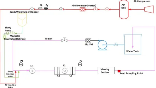
On the sketch of the experimental 2-inch flow loop facility in Figure 1, the red flow line represents the air supply pipe, green line is for sand/water slurry pipe, the blue shows the water pipe flow and the pink represents multiphase flow to the delivery water tank.
Figure 1. A Sketch of Experimental 2-inch Flow Loop Facility used.
3. Results and Discussions
3.1. Wave Structure -Ripple (Annular Flow)
The graphs of Figure 2 (a) and (b) for superficial liquid and gas velocities of 0.0508m/s and 10.0773m/s and that of 0.0501m/s and 23.2796m/s presents, the magnitude of wavelet signals at a given time and frequency. The dominant
Figure 2. (a). Vsl=0.0508m/s, Vsg=10.0773m/s, (b). Vsl=0.0501m/s, Vsg=23.2796m/s.
Further illustrations from the graph of Figure 3 has proven that, at low superficial liquid velocity, the ripple wave effect is prominent. From Figure 3 (a) and (b), the waves were thickly dominant at an average liquid film thickness of 0.1892mm, while the waves were sparsely presented at an average liquid film thickness of 0.23mm, in all the flow conditions respectively.
Figure 3. (a). Vsl=0.0508m/s vsg=10.0773m/s (b). Vsl=0.0501m/s
Vsg=23.2796m/s.
3.2. Disturbance Waves (Annular Flow)
Figure 4 reveals disturbance waves with high velocities, high film thickness, high amplitude and longer-life time. At
circumferentially across the walls of the pipes.
Figure 4. (a). Vsl=0.1892m/s, Vsg=10.3927m/s (b). Vsl=0.1805m/s,
Vsg=23.7259m/s.
Figure 5 (a) and (b), were graphs of liquid film thickness against high superficial liquid velocities of 0.1892m/s and 0.1805m/s with Vsg of 10.3927m/s and 23.7259m/s respectively. The disturbance wave forms a complete ring structures in the pipe.
Figure 5. (a). Vsl=0.1892m/s, Vsg=10.3927m/s (b). Vsl=0.1805m/s,
Vsg=23.7259m/s.
3.3. Liquid Film Thickness (at Bottom of Pipe Using Probes)
The graph of Figure 6, shows that liquid film thickness, decreases with increase in superficial gas velocity, and increases with increase in superficial liquid velocity. The Vsl=0.0505m/s plot, has the lowest film thickness while the superficial liquid velocity of 0.1851m/s represented the highest film thickness. Again, Figure 6 had also shown that, as the superficial liquid velocity increases, the rate of decrease in film thickness becomes insignificant at the bottom of the pipes. This is the impact of gravity on film across the pipe walls as they fall back to the bottom. This mechanism was also noted by [27-26]. For this reason, the graph of Vsl=0.1851m/s in Figure 6 seems to be a straight line with equal heights across all the superficial gas velocity conditions, but they are not in practical sense.
Figure 6. Film thickness (bottom of pipe) against superficial gas velocity.
Figure 7. Film thickness from ring sensor against superficial gas velocity.
3.4. Liquid Film Thickness (Across Entire Pipe Ring Sensors)
velocity from conductivity ring sensors. It shows that film thickness decreases with increase in superficial gas velocity as presented in Figure 6. The Vsl=0.1355m/s had an upward projection because of increase in superficial liquid velocity in the flow loop. The error bar plot on average Vsl=0.1851m/s was the error propagation of ± 0.0844mm of the film thickness which shows the level of accuracy of the measured values.
3.5. Wave Velocity
The graph of Figure 8 shows that, increase in superficial liquid velocity, increases the wave velocity in annular flow. This is because, as the liquid rate increases, momentum transfer between gas core and liquid film increases to create more waves, as also reported by [27, 8, 12, 1, 23, 16]. Thus, the graph further presented, that the lower the superficial liquid velocity, the lower the wave velocity, while the higher the superficial liquid velocity, the higher the wave velocity in horizontal pipe. Again, increase in superficial gas velocity, increases the wave velocity as presented in Figure 8 and also noted by [9].
In all the superficial liquid velocities in Figure 8, the wave velocity increased till a Vsg=18m/s and became stable across superficial liquid velocities. This is simply because, the wave amplitude had attained its peak both at the crest and trough with more interfacial roughness at superficial gas velocities of 18m/s across the entire flow conditions, that no further changes would impact on it.
Figure 8. Wave velocity against superficial gas velocity.
Figure 9. Film thickness against wave velocity.
The graph of figure 9 is for liquid film thickness against wave velocity. It presents, how the wave velocity increases, with decrease in liquid film thickness in annular flow. It means as the wave increases in the pipe, more liquid droplets were been lifted as entrainments, hence decreasing the liquid film thickness at the bottom of the pipe as superficial gas velocity increases in annular flow.
The reason for the increase in wave velocity against decrease in liquid film thickness is because, as more energy was dissipated from the gas core to keep the wave in motion under high wave amplitude as superficial liquid and gas velocities increases, the more faster the liquid films were displaced in the system. This is with respect to the superficial liquid velocities, hence in Figure 9, Vsl=0.0505m/s presented the lower wave velocities compared to Vsl=0.1851m/s.
3.6. Wave Frequency Analysis on Ring Sensors
Wave frequency analysis was presented using conductivity ring sensors’ data from the experiments. The wave frequency results, from the experimental data were achieved using Matlab 2015 version on PSD against Frequency.
Wave frequency plot against superficial gas velocity in Figure 10, shows that wave frequency increases, with increase in superficial gas velocity as reported also by [27, 20, 23, 26]. However, the experimental results of Figure 7, had refuted [28], whose report presented superficial liquid velocities to have insignificant effect on wave frequency.
Figure 10 illustrates the impact of superficial liquid velocity on wave frequency in line with [23] that says wave frequency decreases with increase in superficial liquid velocity. From Figure 10, the wave frequency of Vsl=0.0505m/s was presented to be higher than of wave frequency of Vsl=0.1851m/s. Meaning, wave frequency decreases with increase in superficial liquid velocity in annular flow in horizontal pipe.
Figure 10. Wave frequency against superficial gas velocity.
3.7. Comparing Wave Frequency from Experiments with Correlations
The results from the entire superficial liquid velocities were compared also with different existing wave frequency correlations as follows:
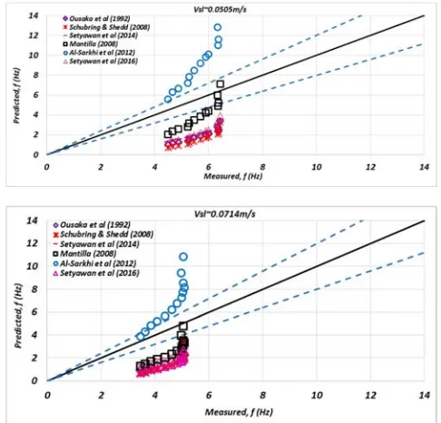
frequency results in the case of superficial velocity of 0.0505m/s. Again, Figure 12 has presented an under-estimation of wave frequency from correlation of [20, 28, 26, 27], while over-estimation of wave frequency from correlation of [2]. The wave frequency from the experiment was between 3.4712Hz to 5.058Hz.
Figure 11. Wave frequency Vs Superficial Gas Velocity (Vsl~0.0505m/s).
Figure 12. Wave frequency Vs Superficial gas velocity (Vsl~0.0714m/s).
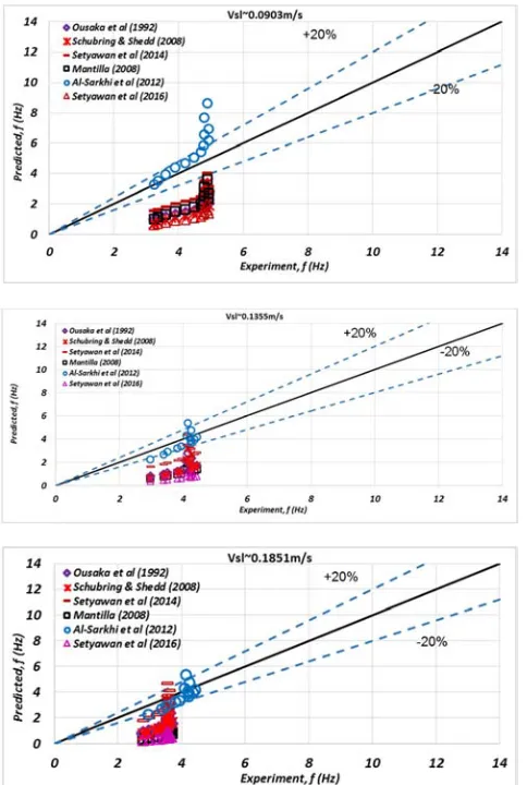
Figure 13. Wave frequency Vs Superficial gas velocity (Vsl~0.0903m/s).
Figure 13 has also shown similar trend with Figure 12, though with the wave frequency from the experiments being in close range with [2], on superficial gas velocities of 8m/s to 14m/s. The wave frequency from the experiments were between 3.2413Hz to 4.8847Hz while [2] correlation wave frequency were between 3.271Hz to 8.638Hz.
Interestingly, Figure 14 has shown a close range among the correlations with the wave frequency from the experiments, and with [2] matching preferably than others. Wave frequency from Figure 14, were between 2.9654Hz to 4.1405Hz while that of [2] were between 2.334 Hz to 5.361Hz. It is also interesting to note, that as the superficial
liquid velocity increases, the wave frequency decrease. This is because, the wave tendency decreases as the liquid film, circumferentially fills the entire walls of the horizontal pipe.
From Figure 15, shows that the entire plots were already matching the measured wave frequency better. In horizontal pipe, it shows that the higher the superficial liquid velocity, the lower the wave frequency. The wave frequency from the experiments, were between 2.7945Hz to 3.5396Hz while [2] correlation wave frequency results were between 1.597Hz to 4.555Hz).
Figure 14. Wave frequency Vs Superficial gas velocity (Vsl~0.1355m/s).
Figure 16. Plots of Performance to identify Correlation that matched the Experimental (Measured) Wave Frequency.
4. Conclusion
In conclusions, the correlations and the experimental results of wave frequency had proven that superficial liquid velocity has impact on wave frequency. From the superficial liquid velocity of 0.0505m/s, the wave frequency from the experiment were between 4.499Hz to 6.4358Hz with Vsg of 8.3179m/s and 23.2796m/s respectively. While at an average superficial liquid velocity of 0.1851m/s, the wave frequency from the experiments were between 2.7945Hz to 3.5396Hz with Vsg of 8.3042m/s and 23.7259m/s respectively. This has shown, that the higher the superficial liquid velocity, the lower the wave frequency and the higher the amplitude, the more disturbing waves are created which forms ring structures across the pipe. The correlation results of [20, 26, 28, 27] differed because the correlations were derived using small pipe diameters of 8.8mm to 26mm compared to this study with 50mm.
From the performance plot of Figure 16, the [2] was the only correlation that matched closely with the measured wave frequency on average Vsl=0.0903m/s, 0.1355m/s and 0.1851m/s. At low Vsl of 0.0505m/s, it was [16] that was preferable.
Acknowledgements
The author would like to express his gratitude to the Oil and Gas Engineering Centre, Cranfield University, Bedfordshire, UK for their support and for making the required instruments available for this work. Also, I
appreciate Prof Falcone, G and Liyun, L for their good
supervision. Special thanks to the PSE Lab Manager, Mr Stan Collins and Shaun, the Technician for their support. And finally, to TETFUND for the sponsorship and to Prof, J. A. Ajienka, my mentor/academic father.
References
[1] Alamu, M. B. and Azzopardi, B. J. (2011) “Wave and Drop Periodicity in Transient Annular Flow”, Nuc., Eng. Des. 241 (12), pp. 5079-5092.
[2] Al-Sarkhi, A., Sarica, C. and Magrini, K. (2012) “Inclination Effects on Wave Characteristics in Annular Gas-Liquid Flows” AIChE J. 58 (4), pp. 1018-1029.
[3] Anderson, R. J and Russell, T. W. F., (1970) “Circumferential Variation of Interchange in Horizontal Annular Two-Phase Flow”, Ind. Engrg. Chem. Fundam. 9, 340-344.
[4] Azzopardi, B. J (1986) “Disturbance Wave Frequencies, Velocities and Spacing in Vertical Annular Two-Phase Flow” Nuclear Engineering and Design, Vol. 92, pp. 121-133. [5] Butterworth, D. (1972) “Air-Water Annular Flow in a
Horizontal Tube”, Prog. Heat Mass Transfer, 6, 235-251. [6] Chien, S and Ibele, W., (1964) “Pressure Drop and Liquid
Film Thickness of Two-Phase Annular and Annular-Mist Flows”, ASME J. Heat Transfer, 86, pp. 80-86.
[7] Fukano, F (1998) “Measurement of Time Varying Thickness of Liquid Film Flowing with High Speed Gas Flow by a Constant Electric Current Method” Nucl. Eng. Des. 184, pp. 363-377.
[8] Fukano, T., Ousaka, A., Morimoto, T. and Sekoguchi, K. (1983) “Air-Water Annular Two-Phase Flow in a Horizontal Tube” (2nd Report, Circumferential Variations of Film Thickness Parameters), Bulletin of the JSME, 26 (218). [9] Furukawa, T., Matsuyama, F. and Sadatomi, M. (2010)
“Effects of Reduced Surface Tension on Liquid Film Structure in Vertical Upward Gas-Liquid Annular Flow” J. Power Energy System. 4 (1), pp. 1-11.
[10] Gawas, K., Karami, H., Pereyra, E., Al-Sarkhi, A. and Sarica, C. (2014) “Wave Characteristics in Gas-Oil Two-Phase Flow in Large Pipe Diameter” Int. J. Multiphase Flow, 63, pp. 93-104.
[11] Han, H, Zhu, Z and Gabriel, K (2006) “A Study on the Effect of Gas Flow Rate on the Wave Characteristics in Two-Phase Gas-Liquid Annular Flow” Nuclear Engineering and Design, Vol., 236, pp. 2580-2588.
[13] Kesana, N. R., Throneberry, J. M., Mclaury, B. S., Shirazi, S. A and Rybicki, E. F, (2012) “Effect of Particle Size and Viscosity on Erosion in Annular and Slug Flow” Proceedings of the ASME 2012 International Mechanical Engineering Congress & Exposition IMECE2012, November 9-15, 2012, Houston, Texas, USA.
[14] Kumar, R., Gottmann, M. and Sridhar, K. R. (2002) “Film Thickness and Wave Velocity Measurements in Vertical Duct” Transactions of ASME 124, pp. 634-642.
[15] Lin, P. Y (1985) “Flow Regime Transitions in Horizontal Gas-Liquid Flow”, PhD. Thesis, Univ. of Illinois, Urbana.
[16] Mantilla, I. (2008) “Mechanistic Modelling of Liquid Entrainment in Gas in Horizontal Pipes” PhD thesis, University of Tulsa, Tulsa, Oklahoma.
[17] McClusky, H. L., Holloway, M. V., Beasley, D. E. and Ochterbeck, J. M. (2002) “Continuous Wavelet Transforms of Instantaneous Wall Pressure in Slug and Churn Upward Gas-Liquid Flow” Journal of Fluid Engineering, Vol. 124, pp. 625-633.
[18] Mori, K., Kondo, Y., Kaji, M. and Yagishita, T. (1999) “Effects of Liquid Viscosity on Characteristics of Waves in Gas-Liquid Two-Phase Flow (Characteristics of Huge Waves and Disturbance Waves). JSME Int. J. Ser. B – Fluids Therm. Eng. 42, pp. 658-666.
[19] Ousaka, A, Deendarlianto, Kariyasaki, A and Fukano, T (2006) “Prediction of Flooding Gas Velocity in Gas-Liquid Counter-Current Two-Phase Flow in Inclined Pipes” Nuclear Engineering and Design, Vol., 236, pp. 1282-1292.
[20] Ousaka, A., Morioka, I. and Fukano, T. (1992) “Air-Water Annular Two-Phase Flow in Horizontal and near Horizontal Tubes: Disturbance Wave Characteristics and Liquid Transportation” J. Multiphase Flow, 6 (9), pp. 80-87.
[21] Osokogwu U (2018) “Evaluation of Wave Frequency Correlations in Annular Flow in Horizontal Pipe” Journal of Scientific and Engineering Research, 5 (7), pp. 75-81. [22] Pan, L. and Hanratty, T. J (2002) (b) “Correlation of
Entrainment for Annular Flow in Horizontal Pipes” Int. J. Multiphase Flow, Vol. 28 (3), pp. 385-408.
[23] Paras, S. V and Karabelas, A. J (1991) “Droplet Entrainment and Deposition in Horizontal Annular Flow” Int. J. Multiphase Flow, Vol. 17, pp. 455-468.
[24] Pearce, D. L. and Fisher, S. A. (1979) A Theoretical Model for describing Horizontal Annular Flows, In Two-Phase Momentum, Heat and Mass Transfer in Chemical, Process and Energy Engineering Systems, pp. 327-333, Hemisphere/McGraw-Hill, Washington, D. C.
[25] Sawant, P., Ishii, M., Hazuku, T., Takamasa, T., and Mori, M. (2008) “Properties of Disturbance Waves in Vertical Annular Two-Phase Flow” Nuclear Engineering and Design, Vol., 238, pp. 3528-3541.
[26] Schubring D. and Shedd, T. A., (2008) “Wave Behaviour in Horizontal Annular Air-Water Flow”, International Journal of Multiphase Flow, 34, pp. 636-646.
[27] Setyawan, A., Indarto and Deendarlianto (2016) “The Effect of the Fluid Properties on the Wave Velocity and Wave Frequency of Gas-Liquid Annular Two-Phase Flow in a Horizontal Pipe” Experimental Thermal and Fluid Science, ELSEVIER, Vol. 71, pp 25-41.
[28] Setyawan, A., Indarto, Deendarlianto. And Prasetyo (2014) “Effects of Surface Tension on the Liquid Holdup and Wave Characteristics in Horizontal Annular Two-Phase Flow” Appl. Mech. Mater. 771, pp. 248-251.
[29] Tellas, A. S and Dukler, A. E., (1970) “Statistical Characteristics of Thin, Vertical, Wavy Liquid Films” Ind. Eng. Chem. Fundam., 9 (3), pp. 412-421.
[30] Weidong, L., Fangde, Z., Rongxian, L., Lixing, Z. (1999) “Experimental Study on the Characteristics of Liquid Layer and Disturbance Waves in Horizontal Annular Flow” J. Therm. Sci. 8 (4), pp. 235-242.
[31] Wilkes, N. S., Azzopardi, B. J and Thompson, C. P. (1983) “Wave Coalescence and Entrainment in Vertical Annular Two-Phase Flow” International Journal of Multiphase Flow, 9 (4), pp. 383-398.