INTRODUCTION
The thermal control system must maintain temperatures of satellite components within their allowable limits throughout the satellite mission. Active and passive methods are used for satellite thermal control. A passive system uses suitable passive thermal hardware, structural material properties, and satellite spin at an appropriate rate to achieve the required thermal control action1.
Satellite structural designs use different materials, which are chosen based on their thermal performance, properties, manufacturing ease and cost2.
Aluminum alloys are the most widely used metallic materials in spacecraft manufacturing. The advantages include high strength to weight ratios, high ductility and ease of machining. The disadvantages include low hardness and a high
Materials Science Research india Vol. 4(1), 25-34 (2007)
Aluminum and composite materials for satellite structures
-A comparison of thermal performance
K.S. NIAKI, A. ANVARI and F. FARHANI
Mechanical Engineering Department, I.R.O.S.T., P.O. Box 15815 - 3538, Tehran (Iran)
(Received: March 20, 2007; Accepted: April 10, 2007)
ABSTRACT
The satellite thermal control maintains temperatures of all satellite components within their allowable operational temperature limits, throughout the satellite mission. Aluminum and composite materials are used for satellite structures. Thermal control performance, structural properties and manufacturing cost are important factors in selection of satellite structures. In this paper, we present the comparison of thermal performance of aluminum and composites, used as structural materials for a small satellite. We have also studied the effect of thermal contact resistance, between the satellite main components and the structural elements, on the overall thermal performance of these satellite structures. The temperature results, for major satellite components in the two types of structures considered in this paper, show the improvement in the overall thermal performance of composite satellite structures over the aluminum satellite structure.
Keywords: Satellite thermal control, aluminum, composite, thermal contact resistance, structural elements, solar panels, batteries, electronic-box.
coefficient of thermal expansion (CTE). The alloys are typically tempered to increase the material strengths. Two typical alloys used in manufacturing are 6061-T6 and 7075-T7.
Composite packaging and structural materials have been used in the development of a variety of spacecraft components, such as thermal doublers, electronic circuit-board heat sinks, advanced battery components, and nonstructural satellite radiators3-5. The use of Carbon-Carbon
(C-C) results in components with thermal conductivities greater than twice that of pure aluminum with a 20 to 40% decrease in weight6,7. These composites
provide excellent paths for the removal of excess heat from electronic devices, resulting in a significant reduction in the overall costs associated with the satellite thermal control8. The New Millennium
radiator and a load bearing structure9. Composite
material was used to manufacture the structure of FORTE satellite10,11.
Fig. -1 shows the thermal conductivity of various carbon composite mater ials and
conventional metals. K1100 fiber12, which has been
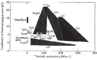
developed specifically for thermal management applications, has a thermal conductivity three times that of copper, and a density one-fourth that of copper. The carbon-composite conductivity values in Fig. -2 are for one-dimensional fibers only.
Fig. -1: Thermal conductivity of carbon composites2.
Fig. -2: Thermal conductivity and coefficient of thermal expansion2.
In this work, three models of the same satellite (a small LEO satellite) have been considered. The first satellite model has an aluminum alloy 7075 structure, while the other two models have composite structures (carbon composites with K1100, and P-140 fibers). The thermal conductivities of the two composite structures, namely composite structure-1 and composite structure-2 are 500 and 700 (W/m-K), respectively. We have used thermal modeling to compare the thermal performance of the three satellite models. To make the comparison possible, other factors such as orbital parameters, internal heat dissipations, components layout and configuration, have been kept identical. The analysis also studies the effect of thermal contact resistance between the satellite main components and the structural elements.
Thermal modeling
The satellite thermal control subsystem design is driven by the design of two passive structural radiators, situated on the top and bottom sides of the satellite (TOP and BASE plates). Our thermal control philosophy is based on control of the thermo-optical properties of all surfaces by means of paints and/or materials with well-known
characteristics. Therefore, the radiators have been painted white (ε > 0.8, ε < 0.2). Solar cells placed on CFRP honeycomb panels with an aluminum core are attached on all lateral sides of the satellite, on top of the structural walls (aluminum or composite). Fig. -3 shows the satellite in β = 60° orbit, where β is the angle between the solar vector and the orbit plane2. The other important orbital parameters are:
• Orbit inclination = 87°
• Orbit Eccentricity = 0 (Circular Orbit) • Orbit Height = 1200 km
• Orbit Period = 120 Min. (7200 Sec)
A simplified model of the satellite has been used for determination of the orbital worst hot and cold cases. The satellite considered is a cube, in which the bottom surface faces the Earth, and the top surface, which acts as satellite radiator, faces
the deep space. The lateral sides are covered with solar panels. The satellite has a slow spin about its Z-axis. Table 1, shows the minimum and maximum values of orbital constants, used for cold and hot cases calculations, respectively [2].
Table-1: Minimum and maximum values of orbital constants used in this analysis
Orbital Constant Minimum Value Maximum Value
Solar constant 1309 W/m2 1400 W/m2
Albedo constant 0.3 0.46
Earth IR 195.6 W/m2 246.1 W/m2
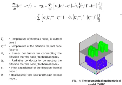
The modeling involves construction of two mathematical models; a Geometrical Mathematical Model (GMM) (Fig.4), and a Thermal Mathematical Model (TMM). The GMM, which consists of submodels such as Electronic Box (E-Box), Telemetry Units, Batteries, Structural elements and Solar panels, is used to calculate the view factors
and the environmental heat fluxes. The TMM is used to calculate the satellite temperatures. The system under consideration is transient, and hence, a transient thermal analysis, based on numerical implicit Forward-Backward method, has been used. The heat balance for a diffusive node is given as13:
(
)
(
)
{
( ) ( )
}
(
)
{
( ) ( )
}
∑
∑
= + + ∧ + + ∧ = +⎥⎦
⎤
⎢⎣
⎡
−
+
−
+
⎥⎦
⎤
⎢⎣
⎡
−
+
−
+
=
−
Δ
N j n i n j ji n i n j ji n i n j ji n i n j ji N j i n i n i iT
T
G
T
T
G
T
T
G
T
T
G
Q
T
T
t
C
1 4 1 4 1 1 1 4 4 1 12
2
...(1) jT = Temperature of thermals node j at current time t,
1
+ n j
T = Temperature of the diffusion thermal node j at t+Δt
ji
G = Linear conductor for connecting the diffusion thermal node j to thermal node i
ji
G
∧
= Radiative conductor for connecting the diffusion thermal node j to thermal node i
i
C = Heat capacitance of the diffusion thermal node i
i
Q = Heat Source/Heat Sink for diffusion thermal node i.
Fig. -4: The geometrical mathematical model (GMM)
Table- 2 presents the allowable temperature limits and Table- 3 shows the heat dissipations of the main components. Batteries have the tightest temperature limits, and the telemetry units have high heat dissipation at transmission time.
In this analysis, two possible operation modes have been considered; the nominal operational mode, in which all components dissipate their maximum heat, and the safe mode, in which one of the telemetry units will be off and hence has no heat dissipation.
Table -2: The allowable temperature limits of main satellite components Main Components Operative Range (°C) Non-Operative Range (°C)
Solar Panels -50 ,+120
-Battery Pack -10 ,+25 -20,+40
Electronic Box (E-Box) -10 ,+50 -40,+80
Telemetry Units -5 ,+50 -50,+50
Structure -80,+80
-Table -3: Heat dissipation of satellite components in the two operational modes
Main Dissipating Power Dissipation in Nominal mode (W)
Components Hot case Cold case
Battery (two packs) 5.5 x 2 0
Telemetry Unit 1 22.5 0
Telemetry Unit 2 22.5 22.5
Electronic Box (E-Box) 12 12
RESULTS AND DISCUSSION
Due to the conductive and radiative links between the main satellite components and structural elements, any variation in temperature of structural elements results in corresponding variations in temperatures of satellite components. In some cases, these variations result in decrease in satellite components, which creates more suitable working conditions for these components.
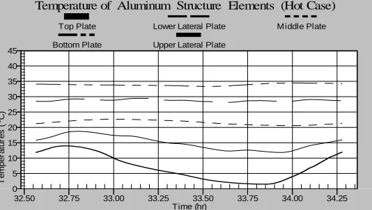
Figure 5 presents the temperature results for the elements of the aluminum satellite structure, consisting of the bottom plate (BASE plate), lower and upper lateral plates, middle plate, and top plate (TOP plate). The top plate acts as the satellite radiator, therefore, it has the lowest temperature. The top plate temperature also follows the fluctuation in the environmental heating absorbed
by the satellite. On the other hand, the bottom plate has the maximum temperature because it has been isolated from the effects of the space environment, using multilayer insulation (MLI), and it supports the high dissipation electronic components (E-Box, UHF/VHF boxes). Fig. -5 shows that for the aluminum structure, the minimum and maximum temperature gradients are 15°C and 27°C, respectively.
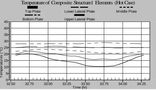
Temperature results for the composite structures are shown in Figs.-6 and 7. The minimum and maximum temperature gradients of satellite components for the composite structure-1 are 8°C and 19ºC, respectively. The minimum and maximum temperature gradients of satellite components for the composite structure-2 are 7°C and 17°C, respectively. Comparison of the temperature results for the structural elements in Figs.-5 through 7 shows that usage of composite structure has Niaki et al., Mat. Sci. Res. Ind., Vol. 4(1), 25-34 (2007)
resulted in a more uniform temperature distribution in the satellite structure, and that the structure elements have temperatures close to each other.
Some of the structure elements show increase in temperature, while the temperatures of some other elements have decreased.
Fig. -5: Temperature of the aluminum structure elements
0 5 10 15 20 25 30 35 40 45
32.50 32.75 33.00 33.25 33.50 33.75 34.00 34.25
Temperature of Aluminum Structure Elements (Hot Case)
T
e
m
p
er
a
tur
e
s
(
°C
)
Time (hr)
Top Plate Lower Lateral Plate M iddle Plate Bottom Plate Upper Lateral Plate
Fig. -6: Temperature of the elements of composite structure-1 (K=500)
Fig. -7: Temperature of the elements of composite structure-2 (K=700)
0 5 10 15 20 25 30 35 40 45
32.50 32.75 33.00 33.25 33.50 33.75 34.00 34.25
Temperature of Composite Structure1 Elements (Hot Case)
T
e
m
p
er
a
tur
es
(
°C
)
Time (hr)
Top Plate Lower Lateral Plate M iddle Plate Bottom Plate Upper Lateral Plate
0 5 10 15 20 25 30 35 40 45
32.50 32.75 33.00 33.25 33.50 33.75 34.00 34.25
Temperature of Composite Structure2 Elements (Hot Case)
T
e
m
per
a
tu
res
(
°C
)
Time (hr)
Top Plate Lower Lateral Plate M iddle Plate Bottom Plate Upper Lateral Plate
Comparison of temperature results for the top plate in the three structures under consideration is shown in Fig. -8. Use of composite structures has resulted in an increase in the temperature of the satellite radiator. However, since the heat radiated to space by a radiator (QR) is proportional to the fourth power of its surface temperature (QRα T4),
the radiative power of the composite satellite radiator has increased in comparison to the aluminum satellite radiator. Also, the decrease in temperatures of some structural elements has resulted in corresponding decrease in temperatures of some main components. This will provide more suitable working conditions for these components.
2.5 5.0 7.5 10.0 12.5 15.0 17.5 20.0 22.5
32.50 32.75 33.00 33.25 33.50 33.75 34.00 34.25
Temperature of Top Plate (Hot Case)
T
e
m
p
er
at
ur
es
(
°C
)
Time (hr)
Aluminum Structure Composite Structure1 Composite Structure2
Fig. -8: Comparison of temperatures for the top plate in the three structures
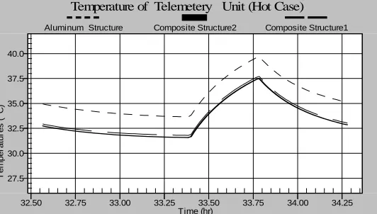
Fig. -9 shows the temperature results for the E-box in the three structures under consideration. Comparison of results shows decrease in E-box temperature for the composite structures, compared to the aluminum structure, mainly due to the decrease in the temperature of the bottom plate (BASE plate) in the composite structure. The same
decrease can be seen in the temperature of the telemetry unit as shown in Fig. -10. The peaks in the temperatures of E-box and telemetry unit, seen for all the three structures (Figs. -9 and 10), are due to the maximum heat dissipations for these units, which occur at the time of data transmission.
Fig. -9: Temperatures of the E-Box in the three structures
26 27 28 29 30 31 32 33 34 35 36 37
32.50 32.75 33.00 33.25 33.50 33.75 34.00 34.25
Temperature of Electronic Box (Hot Case)
T
e
m
per
at
u
re
s
(
°C
)
Time (hr)
Aluminum Structure Composite Structure2 Composite Structure1
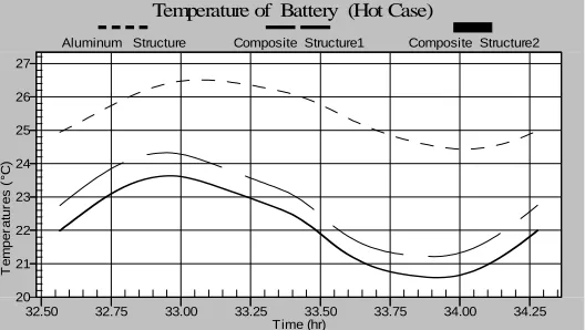
Fig. -11 shows the temperatures of the satellite battery in the three structures. As the battery is placed on the middle plate in the upper section of the satellite structure, and because of the decrease in the middle plate temperature in composite
structures, the battery experiences a temperature fall of about 4°C. This is a significant decrease in the actual operational temperature of the satellite battery, considering the tight temperature limit as shown in Table -2.
Fig. -10: Temperatures of the telemetry unit in the three structures
20 21 22 23 24 25 26 27
32.50 32.75 33.00 33.25 33.50 33.75 34.00 34.25
Temperature of Battery (Hot Case)
T
e
m
p
e
rat
ur
es
(
°C
)
Time (hr)
Aluminum Structure Composite Structure1 Composite Structure2
Fig. -11: Temperatures of the battery in the three structures
Effect of reduced thermal contact resistance Magnitude of the ther mal contact resistance between the satellite main components and structural elements has a strong influence on conduction of the satellite heat dissipations to the satellite radiator. Thermal fillers have been used in all the three models to reduce the contact resistance. However, to demonstrate the effect of thermal contact resistance of bare surfaces, we have re-modeled the structures, by eliminating the ther mal fillers at contact points for all the components. Figs. 12 through 14 show the results
for this analysis case. The temperature results for the structural elements of aluminum and composite structure-2, without the thermal fillers, are shown in Figs. 12 and 13. Due to the reduced heat conduction from the dissipating satellite components to the structural elements, and consequently reduced heat transfer to the satellite radiator, temperatures of structural elements with the exception of the radiator, have increased and the thermal gradient along the structural elements show an increase compared to the structures with thermal fillers.
27.5 30.0 32.5 35.0 37.5 40.0
32.50 32.75 33.00 33.25 33.50 33.75 34.00 34.25
Temperature of Telemetery Unit (Hot Case)
T
e
mp
er
a
tur
e
s
(
°C
)
Time (hr)
Aluminum Structure Composite Structure1 Composite Structure2
Figs 14 and 15 show the temperatures of E-Box and telemetry units, respectively, for the three satellite structures and for the case of increased thermal contact resistance. The slight decrease in the temperature of the bottom plate (Base plate) in the composite structure as compared to the aluminum structure has resulted in corresponding decrease in temperature of E-Box and the telemetry units. Hence, from thermal point of view, the effect of material of satellite structure on temperature of
main components decreases with the increase in thermal contact resistance.
Comparison of temperature results in Figs. 15 and 10 shows that an increase in thermal contact resistance causes a corresponding increase in temperature peak for the telemetry units at time of data transmission. This increase is mainly due to the decreased heat conduction from the telemetry units to the bottom plate.
Fig. -12: Temperatures of aluminum structural elements (without thermal filler)
Fig. -13: Temperatures of composite structure-2 (without thermal filler)
0 5 10 15 20 25 30 35 40 45
32.50 32.75 33.00 33.25 33.50 33.75 34.00 34.25
Temperature of Aluminum Structure Elements (Hot Case)
T
e
m
per
at
ur
es
(
°C
)
Time (hr)
Top Plate Lower Lateral Plate M iddle Plate Bottom Plate Upper Lateral Plate
0 5 10 15 20 25 30 35 40 45
32.50 32.75 33.00 33.25 33.50 33.75 34.00 34.25
Temperature of Composite Structure2 Elements (Hot Case)
T
e
mpe
rat
ur
e
s
(
°C
)
Time (hr)
Top Plate Lower Lateral Plate M iddle Plate
Bottom Plate Upper Lateral Plate
CONCLUSIONS
1. Use of composite structures for a satellite, having the particular design and configuration studied in this work, and a passive thermal control, has resulted in reduction in the temperature gradients along the satellite structure (about 10°C), which is not very significant as far as the structural elements are concerned.
2. Temperature of the satellite radiator in the composite structures is higher as compared to the aluminum structure, which is due to the higher conductivity and hence better transfer of the heat dissipations from various satellite components.
3. Considering the conductive and radiative links between the satellite main components and structural elements, the variations in
structural elements in the composite structures compared to the aluminum structure, have resulted in changes in temperatures of the main components in such a way that the E-box and telemetry units have experienced reduction in temperature. These reduced temperatures have improved the working conditions of the satellite battery which is very important.
4. As far as the satellite thermal control is concerned, the temperature results for main components and structural elements show that the effect of reduced thermal contact resistance is more pronounce than the effect of the materials used in the satellite structure. 5. An increase in the thermal contact resistance has resulted in an increase in the temperature peaks for the telemetry units. Fig. -14: Temperature of the E-box (the case of increased thermal contact resistance)
Fig. -15: Temperature of the telemetry unit (the case of increased thermal contact resistance)
26 27 28 29 30 31 32 33 34 35 36 37
32.50 32.75 33.00 33.25 33.50 33.75 34.00 34.25
Temperature of Electronic Box (Hot Case)
T
e
m
p
er
at
ur
es
(
°C
)
Time (hr)
Aluminum Structure Composite Structure2 Composite Structure1
27.5 30.0 32.5 35.0 37.5 40.0
32.50 32.75 33.00 33.25 33.50 33.75 34.00 34.25
Temperature of Telemetery Unit (Hot Case)
T
e
m
per
at
ur
es
(
°C
)
Time (hr)
Aluminum Structure Composite Structure2 Composite Structure1
1. Farhani, F, A. Anvari, A. and K.S. Niaki, “Investigation on The Effect of Satellite Spin Rate on Satellite Components Temperatures”, 3rd BSME-ASME Inter national Conference on Ther mal Engineering, Dhaka, Bangladesh, 20-22 December, (2006)
2. Gilmore, D.G.: Spacecraft Thermal Control Handbook, Vol. I: Fundamental Techniques, The Aerospace Corporation Press, (2002) 3. Lamm, T.T, “Study of Advanced Satellite
Thermal Management Technology,” The Aerospace Corporation, TOR-98 (1057)-2, (1998).
4. Kibler, J. and Davis, W.E., “Advanced Thermal Application for Carbon-Carbon Composites,” Final report prepared for the Naval Surface Warfare Center, under contract No. N60921-91-D-0020/004 (1992) 5. Maruyama, B. “Progress and Promise in Aluminum Metal Matrix Composites”, Advanced Mater ials and Process Technology, The AMPTIAC Newsletter, Fall, (1998).
6 Glatz, J., Beavers, F., and Vrable, D., “Application of Advanced Composites for Electronic Component Thermal Management in Satellites,” (Written Communication from
REFERENCES
SPARTA, Inc., San Diego, (1994).
7. Kuhn, J., Benner, S., Butler, D., and Silk, E., “Thermal and Mechanical Performance of a Carbon/Carbon Composite Spacecraft Radiator”, NASA/Goddard Space Flight Center, Greenbelt, (1999).
8. “Carbon-carbon for satellite radiator”, Advanced Composites Bulletin, October, (2002).
9. Nicholas, M. T., “EO-1 Technology Validation Report for the Carbon/Carbon Radiator”, Swales Aerospace, Beltsville, Maryland, July 27, (2001).
10. Thompson, T., Butler, T., Knox, S. and Tremblay, G., “FORTE: The All-Composite Satellite”, (1997).
11. Grastataro, C., Butler, T., Smith, B.G., and Thomson, T. C., “Development of a Composite Satellite Structure For FORTE”, Los Alamos National Laborator y, Los Alamos, New Mexico, (1997).
12. Silver man, E.M. and Kagohara, R., “Advanced Composites for Ther mal Management Applications,” report prepared for the NASA Langley Research Center under Contract No. NAS1-19291 (1994). 13. Introduction to SINDA - Version 4.4,
Cullimore and Ring Technologies, (2001). Niaki et al., Mat. Sci. Res. Ind., Vol. 4(1), 25-34 (2007)