_____________________________________________________________________________________________________ *Corresponding author: Email: [email protected];
8(3): 1-10, 2019; Article no.JERR.52804
ISSN: 2582-2926
New Standard Floor Assemble Simulation Approach
for Abaqus Building Structures
Dongyue Wu
1and Wei Chen
1*1
School of Architecture and Civil Engineering, Jiangsu University of Science and Technology, Zhenjiang, 212000, China.
Authors’ contributions
This work was carried out in collaboration between both authors. Author DW designed the study, performed the statistical analysis, wrote the protocol and managed the analyses of the study. Author WC wrote the first draft of the manuscript and accomplished the edit of figures. Both authors read and approved the final manuscript.
Article Information
DOI: 10.9734/JERR/2019/v8i316994 Editor(s): (1)Dr. Hamdy Mohy El-Din Afefy, Professor, Department of Structural Engineering, Faculty of Engineering, Tanta University,
Smouha, Alexandria, Egypt. Reviewers: (1)J. Dario Aristizabal-Ochoa, National University of Colombia at Medellín (Universidad National de Colombia Sede Medellín), Colombia. (2)Tajini Reda, Morocco. (3)Pasupuleti Venkata Siva Kumar, Vallurupalli Nageswara Rao Vignana Jyothi Institute of Engineering & Technology, India. Complete Peer review History:http://www.sdiarticle4.com/review-history/52804
Received 20 September 2019 Accepted 25 November 2019 Published 30 November 2019
ABSTRACT
The mechanical analysis of integral building structure needs the proper ABAQUS finite element analysis, but due to the ABAQUS software function limits the building structure modelling is a great workload and how to model integral structure more quickly and efficiently become a difficult problem. To reduce the workloads in ABAQUS analysis of integral structure models, the new ABAQUS standard floor assemble modelling approach and the program computational algorithm were proposed based on ABAQUS model data structure, nodes geometry transformation and horizontal surface coordinate value distinguish rule. Afterward one example engineering structure model using this standard floor assemble approach and the linear perturbation analysis were completed. The lateral displacement distribution from analysis indicated that each floor lateral displacements distributed continuously without any significant mutation and the standard floor assemble model can successfully achieve the continuous connection of the upper and the lower floors. By comparing the results of ABAQUS standard floor assemble model with that from PKPM SATWE analysis, it is proved that the ABAQUS standard floor assemble modelling is more accurate and can be applied in structure analysis.
Keywords: Standard floor; assemble modelling approach element.
1. INTRODUCTION
With the development of the computer simulation technology in civil engineering, ABAQUS finite element software have been widely used in building structure analysis. While in the application of ABAQUS CAE module, the structural components, including beams, columns, slabs and walls which are usually simulated by shell and beam element, cannot be replicated in large scales [1]. Many scholars studied the model data conversion algorithms between ABAQUS and SAP2000, PKPM SATWE or other finite element simulation software, and based on their study results some reliable model data conversion programs were developed [2,3,4]. While those programs still require modelling process using SAP2000 or PKPM-SATWE to form integral structure model and do nothing to reduce the workload i structure modelling. Apart from the modelling efficiency, the simulation accuracy and stability are usually limited due to the element differences between different software. So, improving the efficiency of the modelling approach of building is very necessary.
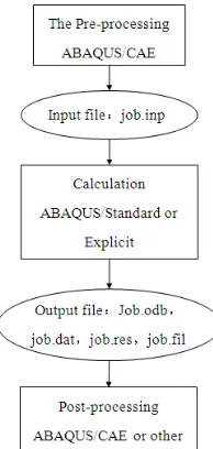
The standard floor drawing method in some software such as Auto CAD, Revit and PKPMA gives a very efficient and operational approach to achieve clear expression of structure components relationship. Therefore, the standard floor expression approach can play as a more efficient and convenient modelling approach under the condition that the ABAQUS finite element software is able to apply the standard floor expression approach. To achieve the successful application of standard floor approach into ABAQUS, the simulation processes and data structure in ABAQUS finite element simulation software should be considered firstly. In a common simulation in ABAQUS software using the CAE model contains three processes of pre processing, calculation and post-process
the relationship and data transfer files are shown in Fig. 1. As the data transfer files, the job.inp is the bridge between pre-processing and calculation, which also contains all the structure data including geometry, material and mechanic. As a basic characteristic of the ABAQUS user interactive CAE model, it is very difficult to accomplish the whole building structure modelling such as that shown in Fig. 2 because the components in building internal space is unable to be reached by CAE operation
assemble modelling approach; building structures; ABAQUS
development of the computer simulation technology in civil engineering, ABAQUS finite element software have been widely used in building structure analysis. While in the application of ABAQUS CAE module, the structural components, including beams, slabs and walls which are usually simulated by shell and beam element, cannot be ]. Many scholars studied the model data conversion algorithms between ABAQUS and SAP2000, PKPM-SATWE or other finite element simulation
and based on their study results some reliable model data conversion programs were developed [2,3,4]. While those programs still require modelling process using SAP2000 or SATWE to form integral structure model and do nothing to reduce the workload in structure modelling. Apart from the modelling efficiency, the simulation accuracy and stability are usually limited due to the element differences between different software. So, improving the efficiency of the modelling approach of building is
The standard floor drawing method in some software such as Auto CAD, Revit and PKPMA gives a very efficient and operational approach to achieve clear expression of structure components relationship. Therefore, the standard can play as a more efficient and convenient modelling approach under the condition that the ABAQUS finite element software is able to apply the standard floor expression approach. To achieve the successful application of standard floor approach S, the simulation processes and data structure in ABAQUS finite element simulation software should be considered firstly. In a common simulation in ABAQUS software using the CAE model contains three processes of
pre-processing, and the relationship and data transfer files are shown in Fig. 1. As the data transfer files, the job.inp is processing and calculation, which also contains all the structure data including geometry, material and mechanic. basic characteristic of the ABAQUS user interactive CAE model, it is very difficult to accomplish the whole building structure modelling such as that shown in Fig. 2 because the components in building internal space is unable to be reached by CAE operation, but it is
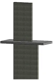
much easier to edit single standard floor model because nearly no internal space was generated in single standard floor, such as that inverted standard floor model shown in Fig. 3. So, the new standard floor-assemble
approach based on ABAQUS can be achieved by using the CAE model only to develop standard floor models and assembling those single standard floor models by editing the .inp files generated into one whole building structure model.
Fig. 1. Step relationships and data fil ABAQUS simulation
Fig. 2. Whole building structure model
ABAQUS; finite
much easier to edit single standard floor model because nearly no internal space was generated in single standard floor, such as that inverted standard floor model shown in Fig. 3. So, the assemble-simulation n ABAQUS can be achieved by using the CAE model only to develop standard floor models and assembling those single standard floor models by editing the .inp files generated into one whole building structure
Fig. 1. Step relationships and data files in ABAQUS simulation
Fig. 3
2. STANDARD FLOOR ASSEMBLE
ALGORITHM
2.1 Geometry transformation of nodes
Nodes geometry transformation is the basic process to achieve the supervision of upper standard floor onto lower standard floor and the connection between different floors. To achieve the geometry transformation of nodes which belong to two different standard fl
marked as A model and B model, the following conditions are proposed:
1) The total node and element quantity in the lower standard floor model A are
respectively.
2) The total node and element quantity in the upper superposed standard floor model B are N′
and M′
, respectively.
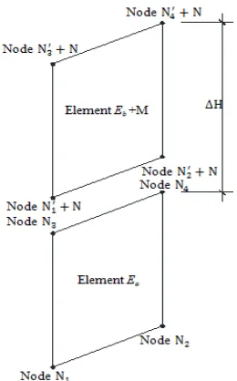
3) Elements in the lower and upper standard floor models are the four-node rectangle element which is widely used as shell element for shear wall and slab. Two four node rectangle elements marked as ‘ ‘Eb’ in the A and B model respectively are shown in Fig. 4.
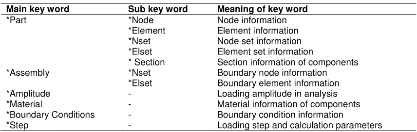
Table 1. Key
Main key word Sub key word
*Part *Node
*Element *Nset *Elset * Section *Assembly *Nset
*Elset *Amplitude - *Material - *Boundary Conditions -
*Step -
Wu and Chen; JERR, 8(3): 1-10, 2019; Article no.
. 3. Inverted single standard floor model
STANDARD FLOOR ASSEMBLE
2.1 Geometry transformation of nodes
geometry transformation is the basic process to achieve the supervision of upper standard floor onto lower standard floor and the connection between different floors. To achieve the geometry transformation of nodes which belong to two different standard floor models marked as A model and B model, the following
The total node and element quantity in the lower standard floor model A are N and M
The total node and element quantity in the upper superposed standard floor model B
Elements in the lower and upper standard node rectangle element which is widely used as shell nd slab. Two four-node rectangle elements marked as ‘Ea’ and
’ in the A and B model respectively are
It contains two sub processes to assemble the two separate elements of ‘Ea’ and ‘
continues element in same model: firstly, superposing the two elements into the condition shown in Fig. 5; and secondly, connecting the two separated elements into continues elements shown in Fig. 6. The two sub processes can be achieved by the following transformation:
(1) Integrate the .inp files of A and B model into one new .inp data file marked as the C model and increase the vertical height coordinate value of all nodes in the upper superposed model B. After the files integration, any node with number
N and element with number M
should be modified into N and M
NN N
MM M
where N and M are the total node and element quantity in model A.
Within the transformation of node vertical height coordinate, all the node vertical height coordinate value in model B will be increased from the initial value of Z into:
Key-words and meaning in ABAQUS .inp file
Sub key word Meaning of key word *Node Node information *Element Element information *Nset Node set information *Elset Element set information
* Section Section information of components *Nset Boundary node information *Elset Boundary element information
Loading amplitude in analysis Material information of components Boundary condition information
Loading step and calculation parameters
; Article no.JERR.52804
It contains two sub processes to assemble the ’ and ‘Eb’ into two continues element in same model: firstly, superposing the two elements into the condition 5; and secondly, connecting the two separated elements into continues elements 6. The two sub processes can be achieved by the following transformation:
les of A and B model into one new .inp data file marked as the C model and increase the vertical height coordinate value of all nodes in the upper superposed model B. After the files integration, any node with number
M in model B
as:
(1)
(2)
where N and M are the total node and element
Within the transformation of node vertical height coordinate, all the node vertical height coordinate value in model B will be increased from the initial
Section information of components
Material information of components
Z Z ∆H (3)
where ∆H is the floor height of the lower standard floor in A model.
After this sub process the relationship of two elements in the new Integrate C model is shown in Fig. 5.
(2) To achieve the connection of the two separated elements shown in Fig. 5 into two continuous elements shown in Fig. 6, the nodes of N′ N and N
′ N shown in Fig. 5 will be
removed and the N and N nodes will be used to replace the N′ N and the N
′ N in the
composition of rectangle element M.
Fig. 4. Element Ea in model A.inp and element Eb in model B.inp
The two sub processes are simple method to achieve superposition and connection for two separated four-nodes rectangle shell elements. While in real building structure, the four-nodes shell element is usually used for vertical shear wall and horizontal slab, and beam element is used for column and beam components. The structure model superposition and connection needs to apply the new proposed ‘horizontal surface coordinate value distinguish rule’.
2.2 Horizontal Surface Coordinate Value Distinguish Rule
For buildings without section change in vertical shear wall and column along the whole building height, when assume that the vertical direction is the z coordinate and the horizontal surface is the x-y surface, all the nodes in vertical continues shear wall or column component should be identical in the x- and y-coordinate values. So, the identical x- and y-coordinate value can be used as distinguish parameter to achieve accurate connections between upper and lower floor models. This new proposed method using identical x- and y- coordinate values as
distinguish parameter to achieve accurate connections is called as the ‘horizontal surface coordinate value distinguish rule’.
Fig. 5. Elements in C.inp model before connection
Fig. 6. Element in C.inp model after connection
section reduction in separated standard floor models should be divided according to reduced shear wall section sizes as the common divisor, as examples shown in Figs.7 and 8.
Fig. 7. Section reduction in vertical shear wall
Horizontal surface coordinate values distinguish rules contain Eqs. (4)-(6) and can be described as following:
1) Nodes in lower standard floor model, of which the z coordinate value matches Eq. (4), will be marked as the replacing nodes set, and all nodes in the upper standard floor model, of which the z coordinate value matches Eq. (5), will be marked as the replaced nodes set.
2) all nodes in the replaced nodes set will be replaced by partial nodes in the replacing nodes set, as all the nodes in replaced nodes set are the vertical components base nodes and all should be replaced to achieve element connection while the nodes in replacing nodes set are same in the z- coordinate and contains floor nodes and are partially used.
3) When the node ‘N0’ in the replacing nodes set and the node ‘Ni’ in replaced nodes set matched Equation (6), the ‘Ni’ nodes will be replaced by the ‘N0’ node.
i 0
i H
Where i is the z coordinate value of any node
and H is the floor height.
Ni N0
Ni N0
Ni ∆H
where ∆H is the floor height of the lower standard floor.
Wu and Chen; JERR, 8(3): 1-10, 2019; Article no.
section reduction in separated standard floor models should be divided according to reduced ar wall section sizes as the common divisor, as examples shown in Figs.7 and 8.
Fig. 7. Section reduction in vertical
Horizontal surface coordinate values distinguish (6) and can be described
lower standard floor model, of which the z coordinate value matches Eq. (4), will be marked as the replacing nodes set, and all nodes in the upper standard floor model, of which the z coordinate value matches Eq. (5), will be marked as
all nodes in the replaced nodes set will be replaced by partial nodes in the replacing nodes set, as all the nodes in replaced nodes set are the vertical components base nodes and all should be replaced to achieve element connection while the replacing nodes set are same in coordinate and contains floor nodes
When the node ‘N0’ in the replacing nodes set and the node ‘Ni’ in replaced nodes set matched Equation (6), the ‘Ni’ nodes will be replaced by the ‘N0’ node.
(4)
(5)
is the z coordinate value of any node
(6)
is the floor height of the lower standard
Fig. 8. Adjustment in two standard floor shear wall with vertical section reduction
Fig. 9. Adjustment in three standard floor shear wall with vertical section
reduction
2.3 Standard Floor Assemble
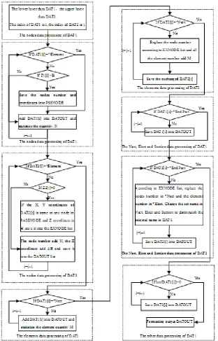
As the basic model information file in ABAQUS software, the .inp file contains all the model information of nodes, elements, sections, materials and calculation parameters, which can be easily edited and indexed by the key words shown in Table 1 [5,6]. According to the geometry transformation of nodes and horizontal surface coordinate value distinguish rules described above, the standard floor assemble algorithm was put forward to form a new integral structure model .inp file by integrating sever separated standard floor model. Fig. 10 is the block diagram of the standard floor assemble algorithm. The algorithm contains eight steps as following:
; Article no.JERR.52804
Fig. 8. Adjustment in two standard floor shear wall with vertical section reduction
Fig. 9. Adjustment in three standard floor shear wall with vertical section
2.3 Standard Floor Assemble Algorithm
Fig. 10. The block diagram of the standard
Fig. 11. Two floors assembled model
Fig. 10. The block diagram of the standard-layer-assemble-modeling algo
Fig. 11. Two floors assembled model
Wu and Chen; JERR, 8(3): 1-10, 2019; Article no.JERR.52804
1) The initial data reading: read the .inp file data and save them into the DAT1 and DAT2 sets shown in Fig. 10 respectively. DAT1 and DAT2 sets are the data storage matrixes, of which the rows are indexed by i and j coordinates, respectively.
2) The lower floor nodes data processing: including four steps of finding the nodes of which the z coordinate equals to the floor height in DAT1, saving those nodes into the PASSNODE list, counting the nodes quantity in DAT1 and formatted outputting the nodes data in DAT1 into the string data list: DATOUT.
3) The upper floor nodes data processing: including four steps of saving the nodes matching Eq. (5) in DAT2 into the EXNODE list, transforming nodes data which do not match Eq. (5) according to Eqs. (1)-(3) and adding the transformed nodes data formatting into DATOUT list.
4) The lower floor elements data processing: counting the total element quantity in DAT1 and formatted adding all the elements data in DAT1 into the DATOUT list.
5) The upper floor elements data processing: requiring all the nodes in DAT2 using EXNODE as the require list, converting the nodes both in DAT2 and EXNODE according to Eqs. (1)-(3) and adding the converted nodes data into DATOUT. 6) The main function of lower floor sets and
sections data processing: directly formatted adding the sets and sections data in DAT1 into DATOUT.
7) The main function of upper layer sets and sections data processing: requiring all the nodes in DAT2 using the EXNODE list as the require list, converting all those nodes both in DAT2 and EXNODE according to Eqs. (1)-(3) and formatted adding the transformed nodes data into DATOUT. 8) The main function of subsequent model
data processing: directly exchanging the ‘Assembly’ and ‘Step’ data of DAT1 and formatted adding to DATOUT.
9) The main function of formatted output: creating a new INP file and formatted outputting the DATOUT into the new .inp file.
By circularly apply the algorithm shown in Fig. 10, the rapid standard floor assemble modelling of integral structure can be achieved and Fig. 11 shows the two-floor assembled model generated by singly apply the algorithm.
3. VERIFICATION EXAMPLE
3.1 Engineering example introduction
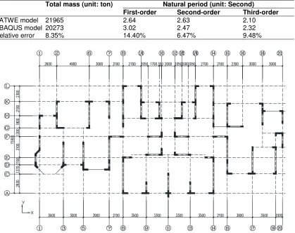
To verify the effectiveness of standard-floor-assemble modelling algorithm, a high-rise structure from actual engineering was selected to model and the linear perturbation analysis was carried out [7]. The example engineering is a residential building contains 32 floors belonging to 11 standard floors. The structure plan of shear walls is shown in Fig. 12. The building is 26.3×15.9 m in plot dimensions and the structure height is 102.7 m. The seismic fortification intensity is the 7th grade, with a 0.15 g earthquake ground motion acceleration, where g is the gravity acceleration of 9.8 m/s2. The concrete strength grade in the example engineering was C35 and the main steel bars were the HRB400 grade, which was the Hot-rolled Ribbed-steel Bar with the yielding strength of 400MPa. All the design parameters of this example engineering structure were determined according to the current design codes in China.
3.2 The Finite Element Structure Model
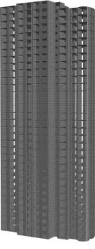
In the first step of the standard floor assemble modelling approach, standard floor models were finished by using the ABAQUS CAE module. The standard floor assemble algorithm applied the file data treatments to the .inp files of single standard floor model. As a result, the basic parameters of the whole structure model and the single standard floor models are the same. The shear walls and floors in models applied the multi-S4R shell elements [8,9], and the beams applied the B31 element. The property of the concrete shell elements is the ABAQUS concrete damage plastic. The property of beams is the PQ-fiber plastic model [10,11]. The whole model generated from 11 single standard floor models are shown in Fig. 13.
3.3 Linear Perturbation Analysis Results
The linear perturbation analysis can easily obtain vibration modes of structure, which can directly reflect structure mechanical properties and be easily compared with results from other structure analysis software. Therefore, the linear perturbation analysis results can be used to verify the accurate of standard floor assemble modelling approach.
Table 2. Calculation results of ABAQUS standard floor assemble model and the SATWE model
Total mass (unit: ton) Natural period (unit: Second)
First-order Second-order Third-order SATWE model 21965 2.64 2.63 2.10 ABAQUS model 20273 3.02 2.47 2.32 Relative error 8.35% 14.40% 6.47% 9.48%
Y
X
Fig. 12. Structure plan of shear walls
translational, the second-order translational and the third-order rotational vibration mode, are sequentially shown in Fig. 14. It can be found that the lateral displacement of each floor distributed continuously without any significant mutation, which means that the standard floor assemble model can achieve the continuous connection of the upper and the lower floors.
To obtain comparable results, the SATWE elastic analysis was also carried out using the PKPM software, which is widely used as design analysis software in China. The main parameters from modes calculation results both of the ABAQUS linear perturbation and the SATWE elastic analysis are shown in Table 2. It can be found from Table 2 that:
1. The total mass of the standard floor assemble structure model is lower than that of the SATWE model with 8.35%. The
reason is that only the dead weight of structural components while the gravitational representative value of uniform constant and live loads are not considered in the ABAQUS linear perturbation calculation. But the relevant error of total mass is very limited with only 8.35% and can be easily controlled by applying uniform constant and live loads through gravitational representative value in further analysis.
assumed to be a rigid floor without any out plane deformation. The stiffness value of standard floor assemble ABAQUS model is lower but more close to real value than that of SATWE model, especially for the stiffness in the x- direction shown in Fig. 14 because the size of x-direction is larger than the size of y direction and the stiffness amplification effect from membrane elements floor is also larger in the x- direction. As a result, the ABAQUS standard floor assemble model is more flexible in the x- direction than that of t SATWE model and the first translational period is larger even with a relative lower total mass. This phenomenon of structural stiffness enlargement from membrane element can also be proved by comparing the 6.47% relevant error of second-order tran
period with the first-order translational period. As the size of y direction is relevant low and the structural stiffness enlargement from membrane element is limited, the second-order translational periods of standard floor assemble ABAQUS model and SATWE model are close. Apart from the membrane elements floor influence, the finite quantity of freedom degrees, which is used to replace an unlimited quantity of freedom degrees to approximate real structure and leads the calculated stiffness larger
structure stiffness, also contributes the calculation error: The maximum element control size of the SATWE model is 1
Fig. 14 a. The first-order translational mode b. c. The
Wu and Chen; JERR, 8(3): 1-10, 2019; Article no.
floor without any out-plane deformation. The stiffness value of standard floor assemble ABAQUS model is lower but more close to real value than that of SATWE model, especially for the direction shown in Fig. 14 rection is larger than the size of y direction and the stiffness amplification effect from membrane elements floor is also larger in direction. As a result, the ABAQUS standard floor assemble model is more direction than that of the SATWE model and the first-order translational period is larger even with a relative lower total mass. This phenomenon of structural stiffness enlargement from membrane element can also be proved by comparing the 6.47% order translational order translational period. As the size of y direction is relevant low and the structural stiffness enlargement from membrane element is order translational periods of standard floor assemble and SATWE model are close. Apart from the membrane elements floor influence, the finite quantity of freedom degrees, which is used to replace an unlimited quantity of freedom degrees to approximate real structure and leads the calculated stiffness larger than real structure stiffness, also contributes the maximum element control size of the SATWE model is 1
meter, while the maximum element control size of the ABAQUS standard floor assemble model is 0.75 meter. Lower element control size means more accurate results.
Fig. 13. The whole structure model
Overall by summarizing the parameters characteristic above, the calculation results of the ABAQUS standard floor assemble model is more accurate and more efficient than that of the SATWE structure model. So the ABAQUS standard floor assemble model is more precise and reasonable. But it should also be noticed that the comparing software case quantity was limited and further verifications should be carried out by other structure simulation software.
order translational mode b. The second-order translational mode The third-order rotational mode
; Article no.JERR.52804
meter, while the maximum element control size of the ABAQUS standard floor assemble model is 0.75 meter. Lower ize means more accurate
Fig. 13. The whole structure model
Overall by summarizing the parameters characteristic above, the calculation results of the ABAQUS standard floor assemble model is more accurate and more efficient than that of the SATWE structure model. So the ABAQUS standard floor assemble model is more precise and reasonable. But it should also be noticed that the comparing software case quantity was limited and further verifications should be carried
tion software.
4. SUMMARIES AND CONCLUSIONS
(1) The ABAQUS standard floor assemble modelling approach can rapidly improve the whole structure modelling efficiency. This approach only requires to use the ABAQUS CAE module to finish the relevant simple single standard floor model and by the afterward algorithmic program, all the individual standard floor models can be assembled into one whole structure model.
(2) The analysis results of the example engineering structure proved that the deformations of floors in the standard floor assemble model distribute continuously with no significant mutation, indicating that the standard floor assemble model approach successfully achieve continuous connection between standard floors and can be applied to structure analysis. (3) Due to the advantages of the ABAQUS
standard floor assemble model in the out-plane deformable shell floor, the elements control size and mesh reasonability, the linear perturbation analysis results from ABAQUS standard floor assemble model are more accurate.
COMPETING INTERESTS
Authors have declared that no competing interests exist.
REFERENCES
1. Lu X, Ye L, Miao Z. Elasto-plastic analysis of buildings against earthquake-theory, model and implementation on ABAQUS, MSC, MARC and SAP2000. (China Architecture & Building Press, Beijing 2009); 2008.
2. Zhang Y, Jiao C, Ding J. Critical issues and software development research on model conversion from SAP2000 to
ABAQUS for complex high-rise structures. Building Structure. 2013;43(6):54-58. 3. Yang X, Fu X, Huang Y. Dynamic
elasto-plastic analysis of the Shenzhen Ping’an Financial Center Tower. Journal of Building Structures. 2011;32(7):40-50.
4. Qiao H, Yang Q, Chen W, Zhang C. Implementation of the Arlequin method in ABAQUS: Basic formulations and applications. Advances in Engineering Software. 2011;42:197-207.
5. Travis T, Hemant P. Analysis of SMA hybrid composite structures in MSC. Nastran and ABAQUS. Journal of intelligent material Systems and Structures. 2007;18:435-449. 6. Faiez G, Ridha H, Tarak B. Optimization of spring back in L-bending process using a coupled Abaqus/Python algorithm. The International Journal of Advanced Manufacturing Technology. 2008;44:61-67. 7. Wu D, Liang S, Shen M, Guo Z, Zhu X,
Sun C, Fu Q. Finite-Element Simulation on NPGCS Precast Shear Wall Spatial Structure Model. Advances in Civil Engineering; 2019.
8. Chen S, Lu X, Ren A, Jiang J. Nonlinear analysis of multi-story concrete frame under fire with fiber beam model. Journal of Building Structures. 2009;30(6):6-16. 9. Ma Q, Ye L, Lu X, Miao Z . Study on lateral
load patterns of pushover analysis using incremental dynamical analysis for RC frame structures. Journal of Building Structures. 2008;29(2):132-140
10. Lin X, Lu X, Miao Z, Ye L, Yu Y, Shen L .Finite element analysis and engineering application of RC core-tube structure based on the multi-layer shell elements. China Civil Engineering Journal. 2008; 42(3):49-55.
11. Zheng M. Inelastic and failure analysis of laminate structure by ABAQUS incorporated with a general constitutive relationship. Journal of reinforced plastics and co; 2007.
© 2019 Wu and Chen; This is an Open Access article distributed under the terms of the Creative Commons Attribution License (http://creativecommons.org/licenses/by/4.0), which permits unrestricted use, distribution, and reproduction in any medium, provided the original work is properly cited.
Peer-review history: