Organized by G. V. S. E. T., Jaipur. Available Online at www.ijpret.com335
INTERNATIONAL JOURNAL OF PURE AND
APPLIED RESEARCH IN ENGINEERING AND
TECHNOLOGY
A PATH FOR HORIZING YOUR INNOVATIVE WORK
GRID CONNECTED SOLAR PV SYSTEM MODELING
PURVI JAIN1, K G SHARMA2, N K GUPTA3
1. Research Scholar, Power System, Govt. Women Engineering College Ajmer, India
2. Associate Professor, Department of Electrical Engineering, Govt. Engineering College Ajmer, India 3. Assistant Professor, Department of Electrical Engineering, Govt. Engineering College Ajmer, India
Accepted Date: 19/03/2018; Published Date: 01/04/2018
Abstract:In this paper a solar PV system is taken for modeling and simulation. Mathematical and electrical models have first been presented. A theoretical background which introduces the topic has been presented. The system's different components have also been described. Then a simulation work of the current voltage (I-V) characteristics and efficiency by using MATLAB/IMULINK has been performed. In order to make the system more flexible for getting maximum power from the power circuit PWM Technique based MPPT is considered. The PWM inverter is used to improve the output current with higher power factor and less variation in load changes. A three pulse PWM inverter is used to design the MPPT which improve the quality of waveform. Finally many disturbances and cases like blackout, load disconnection and islanded system have been investigated. In this work, three test situations have been performed and the corresponding measurements have been recorded. Results that have been obtained showed that the grid connected PV system responds adequately to all the applied disturbances.
Keywords: Solar PV System, PWM, Total Harmonic Distortion
Corresponding Author: PURVI JAIN
Access Online On:
www.ijpret.com
How to Cite This Article:
Purvi Jain, IJPRET, 2018; Volume 6 (8): 335-342 PAPER-QR CODE
SPECIAL ISSUE FOR
NATIONAL LEVEL CONFERENCE
Organized by G. V. S. E. T., Jaipur. Available Online at www.ijpret.com336 INTRODUCTION
With the increase of renewable power, grid connected photovoltaics system are gaining popularity. Due to high cost not many PV system are connected to grid compared to the traditional sources such as coal, wind, nuclear etc. A dropdown in the price of PV system has been seen in recent years due to massive increase in production capacity of PV modules and also due to awareness among the people. Therefore cost reduction has made it more feasible to the use of grid connected PV system.
Solar energy is one of the most important renewable energy sources that have been gaining increased attention in recent years. Solar energy is plentiful; it has the greatest availability compared to other energy sources. It is clean and free of emissions, since it does not produce pollutants or by-products harmful to nature. Conversion of solar energy is done through solar energy collector (stationary and sun tracking concentrating) or photovoltaic panel. The generated current and voltage I-V characteristics are affected by conditions of radiation and temperature [ 1 , 2].
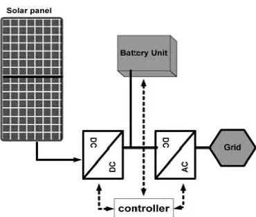
Islanded PV systems are implemented in isolated regions or in places where connection to grid is difficult in less developed countries like India. In contrast, grid connected PV systems are used in developed countries in order to contribute to the electricity share by means of clean non-fossil energy. Measurements for different situations like blackout, load disconnect and islanded have been recorded. The objective is to see the behavior of the system under different possible disturbances. A PV system is composed of the PV solar generator (PV Arrays), the DC-DC converter for the maximum power point tracking and the battery regulation. The batteries unit is used for providing energy on cloudy days and at night and a DC-AC converter for AC loads operation. Basic structure of a PV system is shown in fig. 1. [3-5]
Organized by G. V. S. E. T., Jaipur. Available Online at www.ijpret.com337 The direct conversion of solar energy into electrical power is obtained by solar cells. A PV Generator is composed of many strings of solar cells in series, connected in parallel, in order to provide the desired values of output voltage and current.
In order to improve the efficiency of the grid connected PV system a PWM technique is used to improve the power quality of the output waveform. The PWM inverter is used to produce output current in phase with the voltage for obtaining unity power factor. This technique is more efficient, used to control the output voltage of inverter and reduce the harmonics. The pulse width modulation (PWM) technique mainly consist of single pulse width modulation ,Multiple pulse width modulation, Sinusoidal pulse width modulation, harmonic injection modulation, space vector pulse width modulation, hysteresis (Delta) pulse width modulation. Hysteresis technique is used for current source inverter and rest is used for voltage source inverter. Sinusoidal and space vector technique are used mostly as they reduce the harmonics and control the current.
II. PULSE WIDTH MODULATION TECHNIQUE
PWM technique not only targets Total Harmonic Distortion (THD), but also take care of EMI reduction, lowering the switching loss, better harmonic spectrum. PWM generation technique can be divided as sinusoidal or triangular.
To utilize the present infrastructure of the utility grid for the transmission and distribution, grid tied inverters are required. The DC source will be through PV cell, battery, etc. however the DC input is lower compared to grid voltage, which can be overcome by using DC-DC converter which boost up the voltage to desired level.
Organized by G. V. S. E. T., Jaipur. Available Online at www.ijpret.com338 Fig 2. The following figure shows how pulses are generated for single phase, half bridge three
level converter.
One reference signal is required to generate the four pulses of an arm. A second reference signal is required for single phase full bridge converter to generate the four pulses for the second arm.
These signals are internally generated by phase shifting the original signal by 180 degree. 12 pulses are generated by three Phase Bridge with the use of three reference signals.
III. Grid Connected PV System Modeling
In this study the analysis of grid connected PV array with PWM technique is depicted in fig 2. The system mainly consist of PV module, PWM generator, a high speed step up converter and a system controller connected to utility grid. As the voltage of the PV cell is not very high, due to photovoltaic effect. As PV cell consist of series of cell string all conduct same current, the less efficient cell set the string current, which may cause failure, if any one of the cell will be inactive. Due to this the overall efficiency of the PV array is reduced [1].
PWM full wave bridge inverter consists of four semiconductors and an output inductor, regarded as dc-ac conversion required for the grid connection. As PWM converter is used to produce output current in phase with the utility voltage to obtain the PF.
Organized by G. V. S. E. T., Jaipur. Available Online at www.ijpret.com339 A 250 KV grid is connected to the PV module through an IGBT inverter which is controlled by the PWM generator which generate the firing pulses for the IGBT.
The grid consist of two 25-KV feeders, three loads (2-MW, 250-KW and 30 MW), grounding transformer and equivalent 120- KV transmission system.
The initial input irradiance to the PV array is
1000W/m2 and the operating temperature is 45 degree. C. The system operates at the frequency of 60Hz.
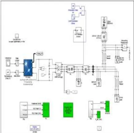
Fig. 3 shows the Simulink diagram of grid connected solar PV system which is being developed in MATLAB Simulink.
Fig 3. 250-KV grid connected PV array with PWM inverter control technique. IV. Simulation results and Discussion
The setup is connected to a 2000W load. Three conditions have been tested on simulation.
Case 1: Blackout by a grid connected PV system:
First, a 4 minutes blackout is applied to the grid connected PV system. The load powers (supplied with the grid or by the PV system) and the frequency have been recorded.
Organized by G. V. S. E. T., Jaipur. Available Online at www.ijpret.com340 Case 2: Grid connected PV system and Load switching
Another test is then performed by switching off the load for l minute and connecting it back when tine PV system is connected to the grid. The recorded measurements are the voltage and the load power and the delivered power by PV panels. One can notice that after a decrease of small voltage, it reaches back to the nominal Voltage level value. The frequency is also goes back to the 50 Hz value after this disturbance of 1 minute. The batteries deliver full power to the load since the PV system gives no power at this time. It was in fact not a sunny day.
Case 3: Islanded PV system and Load switching
The last test is done by switching 'on' and 'off' the load for l minute when the PV system is isolated (not connected to the grid). The recorded quantities are the system output voltage, the frequency and the load powers delivered by the PV system and the storage system. One can notice from results that at time when the load is connected and the voltage decreases to some voltage level then the backup batteries system is activated by the controller and then the voltage is restored back to its nominal value. In the frequency the unbalance between supply and demand happens for I minute then thanks to the batteries system than the 50 Hz is reached again. One can also see that the demand is satisfied through the batteries.
Further Fig. 4 shows the output voltage, output current and PV output power in nominal cases.
Organized by G. V. S. E. T., Jaipur. Available Online at www.ijpret.com341 (b)
(c)
V. CONCLUSION
In this simulation work the behavior of a grid connected PV system under different disturbances has been investigated. The blackout and the load switching during islanding case have been tested. The obtained results showed that the system responds very well in those situations. In fact the nominal (standards) values of the frequency (50 Hz) and the voltage (230 V) are quickly restored. Therefore, a permanent supply of the load is assured either by the PV system or by the grid.
REFERENCES
1. R.J Wai, W.H Wang, “Grid Connected Photovoltaics Generation System”, IEEE Trans.
Circuit & System, vol 55, no. 3, April 2008.
2. H.M kojabadi, B. Yu, I. A Gadoura, L. Chang, M. Ghiribi, “A Novel DSP Based Current
Controlled PWM Strategy for Single Phase grid Connected Inverters”, IEEE Trans. Power Electronics, vol 21, no.4, July 2006.
3. S. Umashanker, Arun Shankar. V.K, G Jain, “Comparative Evaluation of Pulse Width
Organized by G. V. S. E. T., Jaipur. Available Online at www.ijpret.com342
4. S. Jain, V. Agarwal, “A Single Stage grid Connected Inverter Topology for Solar PV Systems
with Maximum Power Point Tracking”, IEEE Trans. Power Electronics, vol. 22, No. 5, September 2007.
5. B. K. Bose, P. M. Szezesny, and R. L. Steigerwald, “Microcontroller control of
residential photovoltaic power conditioning system,” IEEE Trans. Ind. Appl., vol. 21, no. 5, pp. 1182–1191, Sep./Oct. 1985.
6. D. Schekulin, “Grid Connected Photovoltaic System, “Germany patent DE19732218Cl, Mar.
1999.
7. M. Meinhardt, V. Leonavicius, J. Flannery, and S.C.Ó. Mathúna, “Impact of power
electronics packaging on the reliability of grid connected photovoltaic converters for outdoor applications,” Micro electron. Rel., vol. 39, no. 10, pp. 1461–1472, 1999.
8. S. B. Kjaer,J.K.Pedersen,andF.Blaabjerg,“A review of single- phase grid-connected
inverters for photovoltaic Modules,” IEEE Trans. Ind. Appl., vol. 41, no. 5, pp. 1292–1306, Sep./Oct. 2005. [9]. D. G. Holmes and T. A. Lipo. 2003. Pulse Width Modulation for Power Converters: Principles and Practice. M.E. El-Hawary, Ed. New Jersey: IEEE Press, Wiley- Interscience. pp. 215-313.
9. S. J. Huang and F. S. Pai, “Design and operation of grid- connected photovoltaic system