ISSN: 1942-9703 / CC BY-NC-ND Abstract—Drowsy driving is one of the reasons for vehicle
accidents. Recent study found the fact that drowsiness is a bigger risk factor in vehicle accidents than previously thought. This paper proposes a drowsiness alarm which utilizes infrared sensor to detect eyelid position of a driver. The sensor is adequately able to operate in the range of 2-30 cm. After correctly fixed into position, the sensor can evidently detect the left eyelid position of the driver, whether it is closed or open, with the accuracy of above 95%. This eyelid position is taken as the sleepiness symptom of the driver. If a sleepiness symptom is detected, then an alarm is activated. The sound of the alarm is intended to bring the driver back to full consciousness and to prevent possible vehicle crash. The proposed system also consists of a deactivator. The driver must push a correct button sequence in order to deactivate the alarm. Every event of drowsiness is recorded to a smartphone which is connected to the system via Bluetooth connection. This provides time record for further analysis and evaluation. Simulation and testing proved the ability of the sensor to accurately detect eyelid position and confirmed the functionality of the device.
Index Terms—eyelid position detection, deactivator, button sequence, time record.
I. INTRODUCTION
WARENESS of safe driving increases with the development of technology. This increase of awareness led to investigations of factors that may cause vehicle accidents, such as drowsiness [1]. The impact of drowsiness to an accident cannot be neglected since it may cause life loss and material loss. Drowsy drivers are a bigger risk factor in vehicle accidents than previously thought. In 701 crashes within the scope of a research, 8.8-9.5% of them involved drowsiness [2].
Manuscript received June 16, 2018.
Erwin Sitompul is with the Study Program of Electrical Engineering, Faculty of Enginering, President University, Cikarang, 17550, Indonesia. (phone: +62 812 2435 8942; fax: +62 21 8910 9768; e-mail: sitompul@ president.ac.id).
Hamim Maulana was with the Study Program of Electrical Engineering, Faculty of Engineering, President University, Cikarang, (e-mail: [email protected]). July 16, 2018.
Erwin Sitompul is with the Study Program of Electrical Engineering, Faculty of Enginering, Pres, Cikarang, 17550, Indonesia. (phone: +62 812 2435 8942; fax: +62 21 8910 9768; e-mail: sitompul@ president.ac.id).
Hamim Maulana was with the Study Program of Electrical Engineering, Faculty of Engineering, President University, Cikarang, (e-mail: [email protected]).
In complement to studies and implementation of automated systems that help drivers to drive safely such as distance sensor, blind spot assistance, etc., the author is motivated to propose a system that can detect driver’s sleepiness symptom and can give an early warning to prevent probable vehicle accident.
The construction of the prototype started with the study of what type of sensor can be feasibly used to detect sleepiness symptoms. In previous works, a scheme to conduct behavioral measures to the driver was already investigated [3]. A camera was used to monitor yawning, eye closer, eye blinking, and head pose. The use of camera, as mentioned in the report, required the support of daylight and limited the use at night. Besides, head orientation must be maintained in a certain direction. He et al [4] proposed to use sensor of Google glass to monitor eye blink frequency. The frequencies were compared between the state of alertness and drowsiness while driving. In the state of drowsiness, however, the time distribution of eye blinks is as important as the mere count of eye blinks itself. Accurate measurement of low eye blinks frequency also requires a long period of moving average, which may slow down the response of the system.
As the obvious sign of sleepiness is a prolonged eyelid in closed position, the author chose to utilize infrared sensor to detect the condition. Infrared sensor is already known to be able to detect distance accurately within its range of specification. Besides, the sensor module light is adaptable to environment, enabling it to work in low light condition. The utilization of such infrared sensor to detect eyelid position and thereupon deduce the drowsiness of the driver, to the best knowledge of the author, has never been done before and becomes the novelty presented in this paper.
This paper is organized as follows: first an explanation of the system prototype will be presented. The prototype is constrained to be low power and low cost, while compact and portable. This is ensured by the use of radio communication as wireless connection between the deactivator module and the alarm module. Afterwards, each of the components that construct the system will be discussed. The connection using Bluetooth module to send a string of time data to Android device will be discussed in the ensuing section. Finally, simulation and testing results using the prototype are presented.
Drowsiness Alarm Using Infrared Sensor
as Mean of Accident Prevention
Erwin Sitompul and Hamim Maulana
II. BLOCK DIAGRAM OF THE PROPOSED SYSTEM
The connectivity of the drowsiness alarm system is shown in Fig. 1. Each of the alarm module and the deactivator module uses one Arduino Nano as the microcontroller. The FC-51 infrared sensor, real-time clock RTC DS1307, Bluetooth module HC-05, and a buzzer in connected to the microprocessor of the alarm module.
Fig. 1. Block diagram of the drowsiness alarm system
The microprocessor of the deactivator module is connected to a button combination box. One radio frequency module nRF24L01 is attached to each deactivator module (as receiver) and alarm module (as transmitter). This radio frequency connection is chosen so that the deactivator module can be physically separated from the alarm module. This will reduce the burden of having all the system in a bulk. Also, by doing so, the deactivator module can be put within convenient reach of the driver, ready at any time.
The sketch of the alarm module and the deactivator module can be seen in Fig. 2.
(a) (b)
Fig. 2. The modules of the system:
(a) Alarm module, (b) Deactivator module
III. MODULES OF THE SYSTEM
A. Alarm Module
In this module, the infrared sensor will continuously measure the distance between it and the lower part of the driver’s eye. The distance between the sensor and the eye when it is open will be greater than the distance when it is closed. After some initial adjustments, the optimal threshold to differentiate between the states of eye closed and eye open can be determined.
signal is obtained. At the same time, the microcontroller commands the real-time clock to send the time of the event through serial communication via Bluetooth module to a smartphone. This time record can later be used for further analysis and evaluation of driver’s eligibility to drive.
B. Deactivator Module
The activated buzzer can only be deactivated by this module. The driver must prove his resuming alertness by pressing a certain predefined button combination. The deactivator module will be equipped with three buttons. Using the button sequence length of five, for example, 243 different button combinations are available.
By pressing the button combination correctly, the driver proves that he has come back to full consciousness, ready to decide whether to drive further or take rest as precautions.
IV. DESIGN IMPLEMENTATIONS
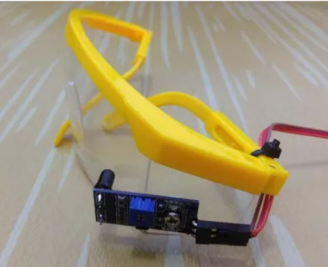
In this phase, the infrared sensor is attached to a commercially available google, as can be seen in Fig. 3. This construction lets the driver to freely move her head while the sensor can still detect the eyelid position. A set of cables connect the sensor to the rest of the alarm module.
Fig. 3. The infrared sensor attached to a google
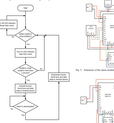
The flowchart of the implemented system is shown in Fig. 4. The drowsiness state is defined to occur when the eyelid is in close position for a period of 1 second. The button sequence chosen to deactivate the alarm is 1-3-2-1-3. This sequence is considered to be simple but adequate to confirm the alertness of the driver.
ISSN: 1942-9703 / CC BY-NC-ND C/C++ language, are divided into setup function which runs
once and loop function which runs repeatedly.
Detect eyelid in close position?
Turn on LED indicator, Start time count
Start
Eyelid in close position more than
1 second?
Activate buzzer, Send time and date data to Android device
Alarm is deactivated?
Deactivate buzzer, Send time and date data to Android device Yes No Yes No No Yes Turn off LED indicator,
Reset time count
Fig. 4. Flowchart of the system
The schematic of the alarm module and the deactivator module are presented in Fig. 5 and Fig. 6. Arduino Nano V3 is used due to small size and completeness. It is based on ATmega328, having 14 digital input/output pins and 8 analog inputs. This board has supported SRAM (Static Random-Access Memory), EEPROM (Electrically Erasable Programmable Read Only Memory), and flash memory. The time record, when needed, can also be stored in EEPROM and later be retrieved. Flash memory is where the program code is stored. D1/TX D0/RX RST GND D2 D3 D4 D5 D6 D7 D8 D9 D10 D11 D12 VIN GND RST 5V A7 A6 A5 A4 A3 A2 A1 A0 AREF 3V3
D13 GND MOSI 5V RST SCK MISO LED Indicator MISO SCK CE GND IRQ MOSI CSN VCC GN D
5V SDA SCL RXD TXD GND VCC
OU T GN D VC C RTC DS1307 ARDUINO NANO V3 IR SENSOR BUZZER BLUETOOTH HC-05 nRF24L01 +
-9V 220Ω
Fig. 5. Schematic of the alarm module
D1/TX D0/RX RST GND D2 D3 D4 D5 D6 D7 D8 D9 D10 D11 D12 VIN GND RST 5V A7 A6 A5 A4 A3 A2 A1 A0 AREF 3V3 D13 GND MOSI 5V RST
SC
K
MI
SO
ARDUINO
NANO V3 10kΩ 10kΩ 10kΩ
MISO SCK CE GND IRQ MOSI CSN VCC nRF24L01 + -9V LED Indicator 220Ω
Fig. 6. Schematic of the deactivator module
V. SIMULATION AND TESTING RESULTS
Fig. 7. The author wearing google with installed infrared sensor
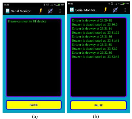
Bluetooth connection between the alarm module and a smartphone is to be initiated first. Afterwards, the time when drowsiness occurs will be recorded and the signal to activate the buzzer was sent, simultaneously. A piezoelectric buzzer is selected to be able to generate awaking sound with low power consumption [6]. When the alarm is successfully deactivated, the time will also be recorded and the buzzer is deactivated. All this can be seen in Fig. 8.
(a) (b)
Fig. 8. The display of Android application interface; (a) Initialization; (b) Time record of drowsiness events
The time delay in the running system is negligible due to short distance between the alarm module, the deactivator module, and the smartphone. Except the google, which is worn by the driver, all other devices are within reach of the driver.
higher than the required distance in the implementation, which is approximately 50 cm.
VI. CONCLUSIONS
An innovative solution to prevent driving accidents due to drowsiness is proposed in this paper. The novel use of infrared sensor to detect the eyelid position was tested and proved to be feasible with high accuracy of 95%. Furthermore, since the sensor is attached to a google, it still can detect the eyelid position in various head orientation. The alarm module and the activator module communicate via radio frequency, which allows the compact and concise construction of the system. The drowsiness alarm system is equipped with real-time clock module and Bluetooth module, which provide time record of the drowsiness events and deactivation events. These data can further be used for analysis and evaluation whether the driver is fit and proper to drive.
The deactivation of the alarm is accomplished by pressing a correct sequence of three buttons on the deactivator module. This ensures the driver’s true state of alertness, since the probability of coincidence is virtually zero, in this case 1/35 or
4.12×10⁻³. The author claims that this approach has never
been done before and completes the uniqueness of the overall system. The resulting prototype was created with a cost of as low as USD 20 and is highly improbable. Thus, if intended for the same purpose of detecting drowsiness by observing eye behavior, the proposed prototype can easily contend similar devices such as Google glass, which is far more expensive.
The current system still uses the duration 1 second of eyelid in close position, in order to change the state from alertness to drowsiness. This duration is constant for all driving speed. Further development will be the use of GPS module which enables measurement of driving speed. The duration that will change the state can then be adjusted to the speed, i.e., to be lower in higher speed.
The proposed system indeed needs more elaborate experiments, not only in simulations which are already conducted, but also in real situation while driving. Further feature that can be implemented is additional scheme to identify and differentiate blinking abnormalities as a mean to detect drowsiness of the driver.
REFERENCES
[1] Torbjorn Akerstedt etal., “Sleepiness at the Wheel,” (White Paper),
Autoroutes & Ouvrages Concedes, France, June 2013.
[2] J. M. Owens, T. A. Dingus, F. Guo, Y. Fang, M. Perez, J. McClafferty, B. Tefft, “Prevalence of Drowsy-Driving Crashes: Estimates for a Large-Scale Naturalistic Driving Study,” (Research Brief), AAA Foundation, Washington, D.C., 2018
[3] A. Sahayadhas, K. Sundaraj, M. Murugappan, “Detecting Driver Drowsiness Based on Sensors: A Review, Sensors (Basel), Dec 2012, pp.16937-53.
ISSN: 1942-9703 / CC BY-NC-ND [6] M. S. Vijaya, “Piezoelectric Materials and Device Applications in
Engineering and Medical Sciences,” Boca Raton, Florida: CRC Press, pp. 94-99, 2016.
Erwin Sitompul was born in Pekanbaru, Indonesia, in 1975. He received the B.E. degree in Engineering Physics from Bandung Institute of Technology, Indonesia in 1998, and M.Sc. and Ph.D. degrees in Electrical Engineering from Technical University Kaiserslautern, Germany, in 2000 and 2005, respectively.
In 2007, he joined the Study Program of Electrical Engineering, President University, Indonesia, as a lecturer. His current research interests include neural networks, fuzzy logics, system modeling and identification, and robotics.