0 INTRODUCTION
Abrasive water jet (AWJ) technology utilizes a high velocity stream of water to accelerate abrasive particles, which then erode a narrow kerf in the material. The main advantages of this technology are the ability to cut virtually all materials without a heat affected zone, while disadvantages are mainly related to relatively poor accuracy, which is usually between 0.05 mm and 0.1 mm [1]. The source of rather poor accuracy lies in the geometrically non-defined and flexible tool which bends as it cuts and starts breaking up as it enters the air. The common result of jet break-up is a tapered and striated cut, which can only be partially solved by tilting the cutting head. Another issue to address in order to achieve high accuracy is determining tool offset, which is currently set to the radius of a new nozzle. This means that parts cut with a new nozzle can achieve accuracies of ±0.08 mm, but as the nozzle wears and diameter increases, the accuracy drops. The other method for determining offset is by cutting a test piece and measuring the dimensions of that piece. The new offset is then calculated from the measured dimensions and the set one [2]. This method is both time consuming and produces waste material. Another problem in the
process is uneven nozzle wear [3], which means that at some point the offset can no longer be adjusted and the nozzle has to be replaced.
Regarding research on AWJ process several simulations were developed [4] which mostly relay on the diameter of the focusing tube as a jet diameter, while reliable measured jet diameter would provide better results.
For industrial applications, a quick and easy to use instrument for measuring jet diameter is needed. An instrument that measures jet diameter prior to machining and displays correct offset would improve cutting accuracy and provide better quality control. Several instruments for measuring jet diameter have already been developed. Orbanić et al. [5] measured AWJ diameter by passing the cutting head over a load cell while AWJ was active. The device determined the diameter by measuring the force of the jet on the load cell at a constant feed rate. The problem arising with this device is the wear to the measuring probe, which then distorts further measurements on that same spot of the probe. Folkes and Li [6] measured the jet diameter using two optical instruments. One instrument was a non-contact LED micrometre which projected a parallel line on the surface of the jet while a CCD camera then measured the contour it formed on
Determining Focusing Nozzle Wear
by Measuring AWJ Diameter
Prijatelj, M. – Jerman, M. – Orbanić, H. – Sabotin, I. – Valentinčič, J. – Lebar, A.
Miha Prijatelj1 – Marko Jerman1 – Henri Orbanić1 – Izidor Sabotin1 – Joško Valentinčič1 – Andrej Lebar1,2,*
1 University of Ljubljana, Faculty of Mechanical Engineering, Slovenia 2 University of Ljubljana, Faculty of Health Sciences, Slovenia
Abrasive water jet (AWJ) cutting is a versatile technology, but it is limited by relative poor accuracy. The main problem is the unknown diameter of the jet, as there is no device or instrument on the market that would enable a quick and easy measurement of it. With such an instrument the diameter could be regularly measured, nozzle wear monitored and noted offset adjusted. This would greatly improve the quality control of the process and the accuracy of the cut. This paper investigates the usage of a through-beam laser sensor for monitoring jet diameter and nozzle wear. Experiments were performed with five differently worn nozzles, with two different water pressures, with and without abrasive, at different standoff distances and with varying measuring times. Results show that the instrument is capable of monitoring the jet diameter and nozzle wear with an accuracy of ±0.03 mm, but it is very susceptible to the jet’s spray and abrasive sticking to the sensor’s screens. Jet diameter correlated better with the diameter of the focusing nozzle when taking measurements without the abrasive, at high water pressures and at a standoff distance of 1 mm.
Keywords: abrasive waterjet, nozzle diameter, jet diameter, nozzle wear
Highlights
• Built an operational device for measuring jet diameter with an optical instrument. • Analysed the effect of water pressure, abrasive and standoff distance on AWJ diameter. • Analysed the effect of measuring time on standard deviation and measuring uncertainty. • Found the correlation between nozzle diameter and jet diameter.
the surface. The other instrument used a narrow beam laser that detected a change in intensity as the AWJ passed across the beam. The diameter was calculated by using a constant feed rate and a time difference between changes in intensity. It is questionable whether it is possible to measure AWJ diameter using a through beam laser, which is an optical instrument for measuring the solid tool diameter. Such a method could be used to monitor nozzle wear, adjust its offset and determine when the nozzle needs to be replaced.
1 FOCUSING NOZZLE WEAR
Due to the aggressiveness of AWJ, the focusing nozzle wears rather quickly. Lifetime depends on numerous AWJ system and nozzle parameters and is usually between 50 hours and 100 hours [3]. As a result of nozzle wear, the jet diameter increases, which decreases the cutting efficiency and precision while increasing its roughness. The nozzle wear principle is shown in Fig. 1. We can see that abrasive appears to erode the nozzle randomly, but eventually a typical wave-like pattern is formed. Wear also depends on orifice and focusing nozzle alignment. Any misalignment causes faster and more uneven wear and may even cause a blowout to occur, i.e. a critical failure in which the AWJ erodes through the side of the focusing nozzle [7]. Uneven wear causes significantly faster jet disintegration and makes the cut wavy, which makes reaching set tolerances impossible.
2 EXPERIMENTAL SETUP
The experimental setup was designed to enable the analysis of AWJ diameter and its correlation to nozzle diameter. In the experiments we analysed the difference between measured jet diameter while using abrasive (AWJ) and while cutting with pure water (WJ). The rationale behind this is that the jet formation mechanism is different. When abrasive is added in the mixing chamber, air is also sucked in, and consequently the jet consists of more than 90 % ambient air [8], which then causes quicker disintegration of the jet. Because of the quick divergence of the jet, it comes into contact with the focusing nozzle earlier and this causes a turbulent flow, which accelerates jet disintegration [9]. When abrasive is not added, the shape of the jet is better maintained, diverging slower, meaning that the jet without abrasive behaves quite differently.
During experiments, the effect of standoff distance on jet diameter was analysed. When the jet
exits the focusing nozzle, it starts to disintegrate; here, the rate of disintegration could hold some important information about nozzle state. Experiments also included analysis of the effect of water pressure on AWJ diameter, as higher water pressures produce a more concentrated jet [10]. The last parameter we analysed was measurement time. Because of AWJ properties such as water pressure oscillations and jet oscillations, a sufficient duration of measurement is important to get a reliable reading, but at the same time it must not be too long to be economical.
Fig. 1. Phenomenological model of focusing nozzle wear
2.1 Measuring Instrument
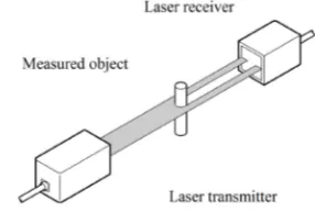
The instrument used for measuring jet diameter was a Keyence digital display compact laser through-beam sensor LX2-V10W series (Keyence, JP). The sensor was designed to measure a diameter or a gap between objects and works using a shadowing method. On one side the line laser emits light and on the other side the receiver measures the amount of light passed through an obstacle. A controller measures the amount of light received and calculates its ratio to the full signal, i.e. the signal in the case there is no obstacle between laser and receiver [11]. The principle of the through-beam sensor is shown in Fig. 2.
The sensor uses a 5 mm wide laser beam with a wave length of 780 nm and repeatability of 10 μm. The controller has an analogue voltage output that was connected to an Arduino Uno microcontroller (Arduino LLC, USA) in order to acquire, process, present and store data.
To avoid water damage it is enclosed in a waterproof casing, as shown in Fig. 3.
Fig. 3. Waterproof casing designed to protect laser sensor from water
2.2 Casing
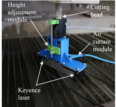
The casing was designed to fit firmly onto the cutting head while enabling height adjustment of the sensor. This is achieved with a threaded rod and a nut. By turning the nut, the sensor is raised or lowered in order to measure the jet diameter at the desired distance from the focusing nozzle.
Both the sensor transmitter and receiver were kept in boxes that are sealed by a transparent screen made from 1 mm thick acrylic glass on one side. The sensor was calibrated using a set of stainless steel gauge blocks. The sensor characteristic is shown in Fig. 4 and shows linear characteristics with correlation coefficient R2 equal to 0.9988.
During the initial tests, some droplets landed on screens of either the laser transmitter or receiver due to the jet spray or its splash back from the catcher tank. As expected, this caused a significant distortion in the measuring results, so a module that creates an air curtain barrier and a splash guard were designed. The air curtain module creates a stream of air at around a 20° angle away from jet to prevent interaction between the jet and air. The splash guard was designed to prevent the splashing of water back
onto the screens while enabling air from air the curtain module to escape. The air curtain module and splash guard are shown in Fig. 5.
Fig. 4. Sensor calibration characteristics
Fig. 5. Cross section of casing showing air curtain and the splash guard
2.3 Measuring the Focusing Nozzle Diameter
the diameter of the nozzles. Positioning accuracy of the microscope table is 0.001 mm.
Nozzles were observed with 30x magnification and illuminated coaxially with microscope objective from above. Nozzle diameter was measured by selecting three points on the inner edge of the nozzle, from which the program then calculated the radius. For every nozzle, the diameter was measured at least four times. The number of measurements depended on the nozzle wear. The more the nozzle was worn, the more times it was measured. Images of nozzle diameters are shown in Fig. 6, and average diameters are shown in Table 1.
Fig. 6. Images of focusing nozzles taken with the Mitutoyo microscope: a) 0.76 mm new, b) 0.76 mm worn, c) 1.02 mm new,
d) 1.02 mm worn, e) 1.02 mm very worn
From the images it can be observed that when the nozzle is new, the hole is almost perfectly round; however, as the wear starts to increase, the roundness
slowly decreases. As a consequence, the jet becomes more unstable and loses its efficiency. For this reason, it is only economical to correct the offset up to a certain point before the nozzle needs to be replaced. Fig. 6e) shows the uneven wear on the focusing nozzle – the reason why, at some point, increasing the offset is no longer an option and the nozzle has to be replaced. That is also the reason why monitoring nozzle wear is of great importance for good quality control.
Table 1. Average focusing nozzle diameter, measured with the microscope
Status Nominal nozzle diam. [mm] Avg. meas. nozzle diam. [mm]
New 0.76 0.832
Worn 0.76 0.904
New 1.02 1.094
Worn 1.02 1.301
Very worn 1.02 1.364
2.4 Experimental Procedure
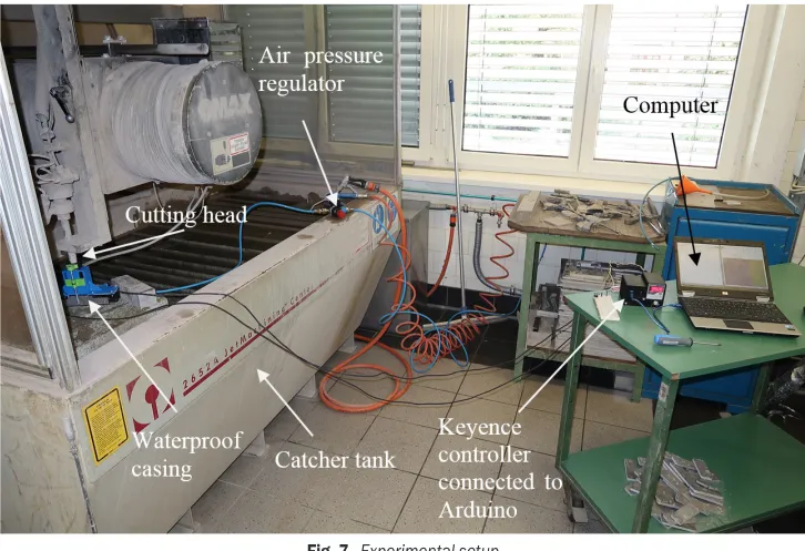
Measurements were conducted on an Omax 2652A machine (Omax, USA), equipped with an Ecotron 403 high pressure water pump (BFT GmbH, Austria) capable of reaching pressures of 400 MPa. Experiments were conducted at water pressures of 200 MPa and 275 MPa using an orifice diameter of
0.3 mm. Measurements were done with and without the abrasive, for which garnet mesh 80# was used. The jet diameter measurements were taken at the exit from the focusing nozzle. The experimental setup is shown in Fig. 7. First, the nozzle was mounted onto the cutting head, and then the casing of the jet diameter measurement system was attached to the cutting head. By turning the nut on the back of the casing, the sensor was raised until it reached the tip of the nozzle. After turning the jet on, the microcontroller started to acquire and interpret the analogue signal from the laser sensor. Collected data was processed offline on a PC. Acquired values were transformed to mm using a calibration equation. Three measurements were taken for each setup combination.
3 RESULTS AND DISCUSSION
3.1 Effect of Water Pressure and Abrasive on Jet Diameter
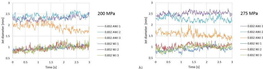
The Arduino program was set to measure the jet diameter for 3 s with a sampling rate of 100 Hz. The purpose of this test was to determine whether it is possible to get a reliable measurement in a short time and to observe the effect of abrasive and water pressure. Fig. 8 shows the measurements obtained by the device. Measurements are labelled according to the new focusing nozzle diameter - type of jet - test number. For example, 0.76 WJ 1 means that particular measurement involves a focusing nozzle 0.76 mm in diameter, without abrasive and is the first repetition. Fig. 8 shows that measurements without abrasive are relatively stable, have a good repeatability and correlate better with measurements taken with the microscope, while measurements with abrasive do not. We assume the reason for the larger jet diameter when using abrasive is that when abrasive mixes with the jet in the mixing chamber, it also sucks in air. This
causes an increase in volume, which, after exiting the focusing nozzle, causes quicker dispersion.
The reason for poor repeatability lies in the spraying of the jet. In cases without abrasive, spraying involves only water, which does not stick to acrylic glass very well and is quickly blown clear by the air curtain module. When using abrasive, the tiniest particles of abrasive dissolved in water droplets tend to stay on the acrylic glass and are not effectively cleared by the air curtain module. As the residue accumulates, measurements become more and more unreliable.
Values of jet diameter labelled with 0.76 AWJ 1 and 0.76 AWJ 2 lie close together, while 0.76 AWJ 3 is notably off. This pattern was also observed in the rest of the measurements, so after preliminary AWJ tests, they were discarded.
In Fig. 8 it can also be observed that jet diameter oscillates rather significantly, which is why these measurements cannot be as accurate as measurements of solid tools.
Results from all measurements are shown in Fig. 9. Blue dots represent measured jet diameter values and orange squares represent measured focusing nozzle diameters. The experiments show that pressure has a significant effect on the correlation between jet diameter and nozzle diameter. Measurements done at 200 MPa are, on average, off by 0.18 mm, while measurements done at 275 MPa are, on average, off by 0.10 mm.
3.2 Determining Optimal Measuring Time
To determine optimal measuring time, results obtained from previous measurements and those measuring only the jet without abrasive and with water pressure of 275 MPa were used. We defined optimal measuring time as the time when either standard deviation or measuring uncertainty significantly decreases. The
a) b)
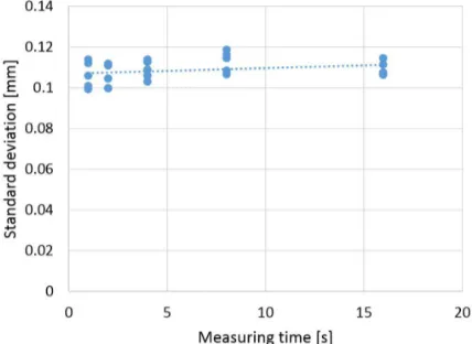
Arduino program was reset to measure jet diameter with a sampling rate of about 3400 Hz for different lengths of time. Measuring times were (1, 2, 4, 8 and 16) s. As the device was measuring diameter, it was also calculating average diameter, standard deviation and measuring uncertainty, where it then displayed these values. Results are shown in Figs. 10 and 11. Results show that measuring time has no effect on standard deviation, so a 1 s measurement would be sufficient. Measuring uncertainty, however, is much more time dependent, as it decreases exponentially. The differences between 1 s, 2 s and 4 s are quite large, while the differences between 4 s, 8 s and 16 s are no longer significant. Another observation showed that repeatability of measurements is also much better after about 4 s compared to those measured at shorter times. Based on these results, we decided the optimal measuring time is 4 s.
Fig. 10. Effect of measuring time on standard deviation of measurement
Fig. 11. Effect of measuring time on measuring the uncertainty of measurement
3.3 Measuring Jet Diameter at Different Standoff Distances
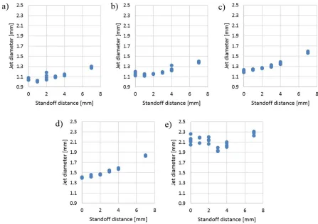
As the jet leaves the focusing nozzle, it starts to disintegrate. Its rate of disintegration depends on numerous parameters, such as condition of the orifice, alignment of the orifice and focusing nozzle, abrasive feed rate and focusing nozzle wear [12] and [13]. In order to measure the rate of jet disintegration below the nozzle exit, the measurement algorithm was adjusted and reloaded in the microcontroller, which acquired and processed data as long as it was needed to achieve the standard uncertainty of the mean value below 0.005 mm. In most of the measurements it took less than a second for the microcontroller to obtain the result with the desired uncertainty. Height adjustment in the present state of the prototype was adjusted manually. Results are shown in Fig. 12. The
a) b)
program was calculating average diameter, standard deviation and measuring uncertainty in real time. Height adjustment was done by turning the nut on the back to raise or lower standoff distance. Results are shown in Fig. 12.
These results show that the jet spreads at a fixed angle; however, for the focusing nozzles with diameters of 0.832 mm and 0.904 mm an interesting phenomenon occurs. Instead of the diameter increasing proportionally with increasing standoff distance, the jet diameter shrinks at the standoff distance of 1 mm. This phenomenon is only present on the small focusing nozzle diameters, and the reason for it remains unknown. It is also possible to see that for the unevenly worn nozzle in Fig. 12e, the jet does not spread at a constant angle, but has almost constant diameter for the first 2 mm, and only afterwards it shrinks and begins to spread at an angle. This type of jet behaviour could lend useful information when determining the uniformity of nozzle wear.
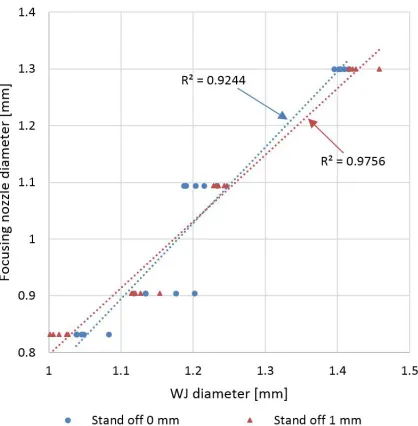
We then compared the correlation between focusing nozzle diameter and WJ diameter at standoff
distances of 0 mm and 1 mm. The nozzle with diameter of 1.364 mm was excluded because it was worn asymmetrically and produced a jet with much greater diameter. Results are shown in Fig. 13.
Results show that there is a much better correlation at standoff distances of 1 mm versus standoff distances of 0 mm. This is likely due to the phenomenon of the jet shrinking at a 1 mm standoff distance. The results also show better repeatability at the standoff distance of 1mm, which makes the measurements more reliable.
Using the linear equation presented in Fig. 13, the program code on the microcontroller was modified in order to calculate jet diameter in real time. With this modification of the program, measurement accuracy improved tremendously. The average difference between the predicted diameter and measured diameter of the focusing nozzle decreases to 0.02 mm, while maximum difference is only 0.07 mm. Most measurements (90 %) are within ±0.03 mm of the corresponding measured nozzle diameter. As expected, however, accuracy significantly decreases
when determining nozzle diameter of the most worn nozzle. The average difference between measured and calculated diameters is 0.80 mm.
Fig. 13. Comparison of measuring WJ diameter at 0 mm and 1 mm standoff distances
4 CONCLUSIONS
In this paper the usage of a through-beam sensor for measuring the jet diameter and determining the focusing nozzle diameter was analysed. The results show much stronger correlation between jet diameter and focusing nozzle diameter at high water pressures, when not using abrasive and at a standoff distance of 1 mm. The main reason for measuring without adding abrasive is that as the jet sprays, residue accumulates on the screens of the instrument and measurements become distorted. Cleanliness in general is the main problem when measuring AWJ diameter. To solve this, we created an air curtain module and a splash guard, which proved to be effective, but not sufficient so as to completely eliminate cleanliness problems. Suggestions for solving this include adding a cleaning module and applying a hydrophobic coating to screens. Before every measurement, screens would be cleaned first, then the instrument calibrated, and only then could the measurement be performed.
With this instrument we managed to determine focusing nozzle diameter to ±0.03 mm. As focusing nozzle diameter is used as a tool offset when setting cutting parameters, knowing the actual diameter would enable a much more accurate cut. This instrument can also be used to monitor nozzle wear,
so that the operator can replace the focusing nozzle as it gets too worn. It was shown that it is also possible to get additional information about the uniformity of nozzle wear from the variation of the measured WJ diameter at different standoff distances; however, this relation has to be researched in greater detail in the future.
The results obtained on the prototype discussed in this paper promise that the concept can be implemented into industrial practice. In order to increase the reliability of the measurement device, a cleaning module should be added and the height adjustment automated. Such an instrument would provide better quality control as well as the possibility to make the cutting process much more automated.
5 ACKNOWLEDGEMENTS
The authors would like to thank to the Slovenian Research Agency for supporting the work in the frame of the Research programme Innovative production systems (P2-0248).
8 REFERENCES
[1] OMAX Corporation (2016). Learn About Waterjets, from
https://www.omax.com/learn/waterjet-cutting, accessed on 2016-11-19..
[2] WaterJets.org (2016). Measuring Kerf and Tool Offset, from
http://www.waterjets.org/index.php?option=com_content&ta sk=view&id=186&Itemid=54, accessed on 2016-11-19. [3] Nanduri, M., Taggart, D.G., Kim, T.J. (2002). The effects of
system and geometric parameters on abrasive water jet nozzle wear. International Journal of Machine Tools and Manufacture, vol. 42, no. 5, p. 615-623, DOI:10.1016/S0890-6955(01)00147-X.
[4] Jerman, M., Valentinčič, J., Lebar, A., Orbanić, A. (2015). The study of abrasive water jet cutting front development using a two-dimensional cellular automata model. Strojniški vestnik - Journal of Mechanical Engineering, vol. 61, no. 5, p. 292-302, DOI:10.5545/sv-jme.2014.2179.
[5] Orbanić, H., Junkar, M., Bajsić, I., Lebar, A. (2009). An instrument for measuring abrasive water jet diameter. International Journal of Machine Tools and Manufacture, vol. 49, no. 11, p. 843-849, DOI:10.1016/j. ijmachtools.2009.05.008.
[6] Folkes, J., Li, Z.J. (2010). Innovative method of water jet diameter measurement for process and quality control. 20th
International Conference on Water Jetting, p. 329-340. [7] Hashish, M. (2003). Inside AWJ Nozzles. WJTA American
Waterjet Conference, p. 1-D.
[9] Agrawal K.S. (2013). Breakup of liquid jets. International Journal of Emerging Technologies in Computational and Applied Sciences, no. 5, p. 487-496.
[10] Birouk, M., Lekic, N. (2009). Liquid jet breakup in quiescent atmosphere: a review. Atomization and Sprays, no. 6, p. 501-528, DOI:10.1615/AtomizSpr.v19.i6.20.
[11] Keyence (2016). Laser Thrubeam Photoelectric Sensor LX2(W) Series. Instruction manual. Keyence, Osaka,
[12] Stevenson, A.N.J., Hutchings, I.M. (1995). The influence of nozzle length on the divergence of the erodent particle stream
in a gas-blast erosion rig. Wear, vol. 189, no. 1-2, p. 66–69, DOI:10.1016/0043-1648(95)06641-1.