ORIGINAL ARTICLE
New Family of 3-DOF UP-Equivalent
Parallel Mechanisms with High Rotational
Capability
Wei Ye, Qin‑Chuan Li
*and Xin‑Xue Chai
Abstract
Parallel mechanisms (PMs) having the same motion characteristic with a UP kinematic chain (U denotes a universal joint, and P denotes a prismatic joint) are called UP‑equivalent PMs. They can be used in many applications, such as machining and milling. However, the existing UP‑equivalent PMs suffer from the disadvantages of strict assembly requirements and limited rotational capability. Type synthesis of UP‑equivalent PMs with high rotational capability is presented. The special 2R1T motion is briefly discussed and the fact that the parallel module of the Exechon robot is not a UP‑equivalent PM is disclosed. Using the Lie group theory, the kinematic bonds of limb chains and their mechanical generators are presented. Structural conditions for constructing such UP‑equivalent PMs are proposed, which results in numerous new architectures of UP‑equivalent PMs. The high rotational capability of the synthesized mechanisms is illustrated by an example. The advantages of no strict assembly requirements and high rotational capability of the newly developed PMs will facilitate their applications in the manufacturing industry.
Keywords: Parallel mechanism, Group theory, Type synthesis, High rotational capability
© The Author(s) 2018. This article is distributed under the terms of the Creative Commons Attribution 4.0 International License (http://creativecommons.org/licenses/by/4.0/), which permits unrestricted use, distribution, and reproduction in any medium, provided you give appropriate credit to the original author(s) and the source, provide a link to the Creative Commons license, and indicate if changes were made.
1 Introduction
Among the various lower mobility parallel mechanisms(PMs), those with two rotational and one translational motion(2R1T) are particularly useful and can be implemented in many applications. The Z3 head [1], whose parallel part is a 2R1T 3-PRS PM(P is a pris-matic pair, R is a revolute pair, and S is a spherical joint), is the most well-known. Another example is the 2-UPR-SPR PM(U denotes a universal joint), which has been successfully used in the development of the Exechon robot [2].
It should be noted that different 2R1T PMs may have distinct motion characteristics. According to the virtual chain method [3], they can be classified into three cat-egories: PU-equivalent PMs, RPR-equivalent PMs, and UP-equivalent PMs.
A PU-equivalent PM can perform three degrees of free-dom (3-DOF) motion that is identical to the end motion
of a PU serial chain. The two axes of rotation always intersect and remain perpendicular. In other words, the rotation center of a PU-equivalent PM is restricted to a line; thus, the so-called parasitic motion [4] is eliminated. There were few PU-equivalent PMs until the authors of this paper systematically investigated their type synthesis [5].
An RPR-equivalent PM can perform 3-DOF motion that is the same as the end motion of an RPR serial chain. The two rotational axes are in different planes and are perpendicular. Li and Hervé [6, 7] disclosed numerous architectures of the RPR-equivalent PMs. This type of mechanism can be used in many applications where high stiffness and dexterity are required, such as in five-axis machining [8], aircraft wing assembly [9], and friction stir welding [10].
A UP-equivalent PM can perform 3-DOF motion that is identical to the end motion of a UP serial chain. One axis of rotation is fixed to the base while intersecting and remaining perpendicular to the other. Such features lead to reduced complexity in kinematic model, control, calibration and are thus preferable in practice. There are
Open Access
*Correspondence: lqchuan@zstu.edu.cn
two ways to construct UP-equivalent PMs. The first is to either add a passive UP serial chain to a 6-DOF 3-UPS PM, like the Tricept robot [11], or add an articulated UP serial chain to a 6-DOF 2-UPS PM, like the TriVariant robot [12, 13]. The passive or articulated UP serial chain constrains the motion of the moving platform, and no strict geometrical condition is required. Thus, the Tricept and TriVariant robots are widely used in manufacturing and assembly.
The second is to use identical limb chains. Kong and Gosselin first studied the type synthesis of UP-equivalent PMs using screw theory [3]. They systematically enumer-ated numerous architectures. However, these architec-tures require strict geometrical conditions, such as the intersection of three or more revolute axes at a common point in space, which is very difficult to implement in practice.
In addition, one may think that the parallel module of the Exechon robot [2], which is a 2-UPR-SPR PM, belongs to the UP-equivalent PMs family. In the follow-ing section, we demonstrate that the mechanism is not a UP-equivalent PM.
Although the UP-equivalent PMs output 2R1T motion, their reachable workspaces are usually of concern since they are used for locating in most applications. However, it should be noted that their reachable workspaces are highly dependent on their rotational capabilities since the position variations of the moving platforms in two direc-tions are generated by the two rotational modirec-tions of the mechanisms. The reachable workspaces of the Tricept and TriVariant robots are not large because their rota-tional capabilities are limited to some extent by spheri-cal joints, particularly with the existence of multiple spherical joints. It is meaningful to expand the rotational capabilities of UP-equivalent PMs to ultimately achieve considerable reachable workspaces.
In this paper, we attempt to invent new architectures of UP-equivalent PMs with high rotational capability and low geometrical condition requirements. That is, the new architectures of UP-equivalent PMs should contain
no spherical joints and should avoid a common point of intersection of several revolute axes in space. Theoreti-cally, type synthesis of PMs with two rotational DOFs is more difficult and complicated than that of PMs with either one or no rotation. Hence, although considerable progress has been made in terms of the general method for type synthesis of lower-mobility PMs [14–27], and some 3T or 3T1R PMs with specified kinematic prop-erties have been proposed [28–32], few architectures of UP-equivalent PMs without spherical joints and strict assembly requirement have been disclosed.
The organization of this paper is as follows. Section 2
presents a brief introduction of notations and proper-ties of the UP-equivalent motion. Section 3 discusses the limb bonds of the UP-equivalent PMs. Section 4 con-structs the UP-equivalent PMs in a special category. Sec-tion 5 illustrates the rotational capability of the proposed mechanisms. Section 6 discusses the application of the proposed PMs. Section 7 summarizes the conclusions.
2 Special 2R1T Motion 2.1 Notations
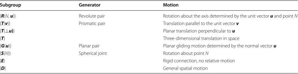
Firstly, a brief introduction of the Lie group theory is given. Some displacement subgroups used in this paper are listed in Table 1. For more details about Lie group theory, please see Refs. [14–20].
Since there are usually some special geometrical con-ditions in lower mobility PMs, superscripts are used in the following sections to indicate the axial direction of the kinematic pairs. For instance, uP represents a pris-matic pair with its axis parallel to vector u; uR denotes a revolute pair whose axis is parallel to vector u; and uvU represents a universal joint whose two rotational axes are parallel to vectors u and v, respectively. In contrast, the spherical joint is denoted by S without superscript since it allows rotation around any axis passing through its center.
In view of practical values, limbs that contain two or more prismatic pairs, helical pairs, and parallelogram are neglected here. However, UP-equivalent PMs with these
Table 1 Displacement subgroups
Subgroup Generator Motion
{R(N, u)} Revolute pair Rotation about the axis determined by the unit vector u and point N
{T(v)} Prismatic pair Translation parallel to the unit vector v
{T(⊥u)} Planar translation perpendicular to u
{T} Three‑dimensional translation in space
{G(u)} Planar pair Planar gliding motion determined by the normal vector u
{S(N)} Spherical joint Rotation about point N
{E} Rigid connection, no relative motion
pairs can also be synthesized following the method raised in this paper.
2.2 Special 2R1T Motion
A special 2R1T motion can be represented by product {R(O, u)}{R(O, v)}{T(w)}. Such a motion can be generated by a uvUwP chain or a uRvRwP chain. The rotation center O is fixed, and thus no parasitic motion exists.
A displacement set of {R(O, u)}{R(O, v)}{T(w)} is obtained by the composition of three displacements. The first displacement is a translation parallel to w:
where the real number t is the translation amplitude. The second displacement is a rotation of angle ψ around axis (O, v):
Since OMT = tw + OM, the transformation of M into
MR1 is expressed by
The third displacement is a rotation of angle φ around axis (O, u). The point MR1 is transformed into the final position M′ as
which expresses the transformation M→M′.
The displacement M→M′ is the product of spheri-cal rotation M→MR = O+exp(φu×)exp(ψv×)(OM), followed by translation MR→M′ = MR + texp(φu×) exp(ψv×)w.
2.3 Special Case: Exechon Robot
Figure 1 shows a 2-UPR-SPR PM that is the parallel mod-ule of the Exechon robot. Intuitively, it is often thought that the 2-UPR-SPR PM is a UP-equivalent PM. However, this is not true.
Limb 1 and limb 3 are UPR chains. Limb 2 is an SPR chain. A1 and A3 denote the central points of the two U-joints in limb 1 and limb 3, respectively. A2 denotes the center of the spherical joint in limb 2. Bi(i = 1, 2, 3) denotes a point on the revolute axes adjacent to the mov-ing platform in limb i. Counting from the base, the first revolute axes of the two U-joints are coincident. The fourth revolute axes in limb 1 and limb 3 are parallel, and perpendicular to the fifth revolute axis in limb 2.
The kinematic bond of limb 1 is {L1} = {R(A1, u)} {R(A1, v)}{T(x1)}{R(B1, v)}, where x1 is a unit vector in the
(1) M→MT=tw+M,∀pointM,
(2)
MT →MR1=O+exp(ψv×)(OMT).
(3) M→MR1=O+exp(ψv×)(OM+tw).
(4) MR1→M′=O+exp(ϕu×)(OMR1)
=O+exp(ϕu×)exp(ϕv×)(OM+tw)
=O+texp(ϕu×)exp(ϕv×)w
+exp(ϕu×)exp(ϕv×)(OM),
uw plane and is perpendicular to v. Using product clo-sure, we have {L1} = {R(A1, u)}{G(v)} = {R(O, u)}{G(v)}, because O is also a point on the first revolute axis.
The kinematic bond of limb 3 is {L3} = {R(A3, u)}{R(A3,
v)}{T(x3)}{R(B3, v)}, where x3 is a unit vector in the uw plane and is perpendicular to v. Through a similar analy-sis to that of limb 1, we have {L3} = {R(O, u)}{G(v)}.
Since {L1} = {L3}, we only need to discuss the intersec-tion of the displacement sets produced by limb 1 and limb 2. The kinematic bond of limb 2 is {L2} = {R(A2, v)} {R(A2, u)}{R(A2, x2)}{T(x2)}{R(B2, u)}, where x2 is a unit vector in the vw plane and is perpendicular to u.
Because {R(A2, v)}{R(A2, u)}{R(A2, x2)} = {S(A2)}, we have
The intersection of limb 1 and limb 2 is given by
It is simple to determine {G(v)}∩{G(u)} = {T(w)}.
Hence, {G(v)}and {G(u)}can be decomposed into prod-ucts, including the factor {T(w)}, as
Substituting Eq. (7) and Eq. (8) into Eq. (6) yields
Because {R(O, u)}{R(O, v)}≠{R(O, v)}{R(O, u)}, {R(O, u)}{R(O, v)}{T(u)}∩{S(A2)}{G(u)} is only a
(5) {L2} = {S(A2)}{T(x2)}{R(B2, u)}
= {S(A2)}{R(A2, u)}{T(x2)}{R(B2, u)} = {S(A2)}{G(u)}.
(6) {L1} ∩ {L2} = {R(O, u)}{G(v)} ∩ {S(A2)}{G(u)}.
(7) {G(v)} = {R(O, v)}{T(u)}{T(w)},
(8) {G(u)} = {R(A2, u)}{T(v)}{T(w)}.
(9) {L1} ∩ {L2}
= {R(O, u)}{R(O, v)}{T(u)}{T(w)} ∩ {S(A2)}{G(u)}{T(w)}
two-dimensional submanifold of {R(O, u)}{R(O, v)} {T(u)}. Hence, although the parallel module of the Exe-chon robot has three DOFs, it is not a UP-equivalent PM.
3 Limb Bond of UP‑Equivalent PMs 3.1 Displacement Set of UP‑Equivalent PMs
The motion generated by a UP chain has three DOF. Hence, three limbs are preferable for the UP-equivalent PMs. Each limb generates a set of feasible displacements (or kinematic bond) denoted by {Li}, (i = 1, 2, 3). {R(O,
u)}{R(O, v)}{T(w)} must be the intersection of all limb kinematic bonds produced by all limb chains. Hence, we can write
3.2 Limb Bond of UP‑Equivalent PMs
Obviously, {R(O, u)}{R(O, v)}{T(w)} should be included in the displacement set {Li} generated by the ith limb chain, that is, {R(O, u)}{R(O, v)}{T(w)}⊂{Li}. If one or two limbs are sufficient to produce a UP motion, one or two genera-tors of {D} can be the second and third limb. For example, one can construct a UP-equivalent PM using two 6-DOF SPS or UPS limbs, and one uvUwP chain. This is straight-forward and is not discussed in this paper. We only focus on the type synthesis of UP-equivalent PMs with lower-mobility limbs.
There are three groups of limb bonds, distinguished by their dimensions (Dim).
Group 1: Dim({Li}) = 3
This corresponds to only one condition, i.e., {Li} = {R(O, u)}{R(O, v)}{T(w)}. The corresponding mechanical generator (MG) is a 3-DOF uvUwP chain. However, one cannot construct a UP-equivalent PM with three identical uvUwP chains.
Group 2: Dim({Li}) = 4
To obtain 4-DOF limbs, one can add {R(O, u)}{R(O,
v)}{T(w)} to a 1-D subgroup. Only results that yield sub-groups of {D} are considered here. A 1-D translational subgroup or rotational subgroup can be selected as the added factor.
Adding {R(O, u)}{R(O, v)}{T(w)} to a 1-D translational subgroup {T(t)} yields
{T2(w, t)} is generated by a serial array of two prismatic pairs. However, it is discarded because limbs with two prismatic pairs are not considered for practical purposes.
With added factor {R(A, w)}, we have
(10) 3
i=1
{Li} = {R(O, u)}{R(O, v)}{T(w)}.
(11) {Li} = {R(O, u)}{R(O, v)}{T(w)}{T(t)}
= {R(O, u)}{R(O, v)}{T2(w, t)}.
Note that the point A does not necessarily belong to axis (O, w). However, if the end-effector motion is con-strained by the other two limbs to be {R(O, u)}{R(O, v)} {T(w)}, then there is no motion in the R pair embodying {R(A, w)}. Hence, combination {R(O, u)}{R(O, v)}{C(A,
w)} is discarded.
If A∈axis(O, w), Eq. (12) becomes
The 3-D group {S(O)} is equal to product{R(O, i)}{R(O,
j)}{R(O, k)} provided that (i, j, k) is a vector base. With
k = w, we have{R(O, i)}{R(O, j)}{R(O, w)}{T(w)} = {R(O,
i)}{R(O, j)}{C(O, w)} and we can use {C(O, w)} = {T(w)} {R(O, w)}, which gives {R(O, i)}{R(O, j)}{T(w)}{R(O, w)}, where i≠u and j≠v.
With added factor {R(A, v)}, we have
The 3-D group {G(v)} is equal to {R(A, v)}{R(B, v)} {T(r)} with generally A≠O and r⊥v≠w. We also have {G(v)} = {R(A, v)}{T(r)}{R(B, v)} = {T(r)}{R(A, v)}{R(B,
v)} = {R(A, v)}{R(B, v)}{R(C, v)}.
In summary, we obtain two types of 4-D products: {S(O)}{T(w)} = {R(O, i)}{R(O, j)}{C(O, w)} with i ≠ u and
j≠v, and {R(O, u)}{G(v)}, in which the cylindrical 2-D group, spherical 3-D group, and planar 3-D group can be decomposed into products of their 1-D subgroups. Table 2 lists the 4-D limb bonds and their MGs of UP-equivalents PMs.
Group 3: Dim({Li}) = 5
With added factor {R(A, k)}{R(B, k)}, we have
Thus, various MGs can be obtained by using product closure in {G(k)}, as listed in Table 3.
Adding a group of translation {T(t)}, and ∀ unit vector
t ≠ w, in the 4-D product {S(O)}{T(w)}, we obtain
{S(O)}{T2(w, t)} is an irreducible representation of the reducible product {S(O)}{G(s)}, with s⊥w (the planes orthogonal to s are parallel to w).
{S(O)}{G(s)} has two main categories of irreducible rep-resentations. One is {R(O, i)}{R(O, j)}{G(s)}, where (i, j, k)
(12) {Li} = {R(O, u)}{R(O, v)}{T(w)}{R(A, w)}
= {R(O, u)}{R(O, v)}{C(A, w)} = {R(O, u)}{R(O, v)}{R(A, w)}{T(w)}.
(13) {Li} = {R(O, u)}{R(O, v)}{R(A, w)}{T(w)}
= {R(O, u)}{R(O, v)}{R(O, w)}{T(w)} = {S(O)}{T(w)}.
(14) {Li} = {R(O, u)}{R(O, v)}{T(w)}{R(A, v)}
= {R(O, u)}{G(v)}
(15) {Li} = {R(O, u)}{R(O, v)}{T(w)}{R(A, k)}{R(B, k)}
= {R(O, u)}{R(O, v)}{G(k)}.
is a vector base (generally, i ≠ u and j ≠ v). The other is {S(O)}{G2(s)}, where {G2(s)} denotes one of the 2-D submanifolds of the 3-D group{G(s)}. We neglect {S(O)} {G2(s)} intentionally because a spherical joint is needed to implement {S(O)}. Table 4 lists the MGs of 5-D limb bond {R(O, i)}{R(O, j)}{G(s)}.
Adding a 2D group of planar translations in product {R(O, u)}{R(O, v)}{T(w)}, we obtain
{X(u)}{X(v)} is called the double Schoenflies motion or X–X motion [18]. It is reducible and includes three translations and two rotations. The axes of the rotations are parallel to vectors u and v, whereas the locations of the axes can be arbitrary. For detailed MGs of the X–X motion, please see Ref. [18].
3.3 Parallel Arrangement of Limbs
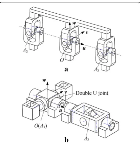
A UP-equivalent PM can be obtained by connecting a moving platform to a fixed base using the three limbs listed in Table 2 or Table 3. Note that the U-joints in the three limbs must be coincident, which causes difficul-ties in fabrication and actuation. Henceforth, we use the first revolute axis to denote the fixed revolute axis of the U-joint and the second axis to denote the moving revo-lute axis of the U-joint.
We set the first revolute axes of the U-joints in limbs 2 and 3 to be coincident with the first revolute axis of (17) {Li} = {R(O, u)}{R(O, v)}{T}
= {X(u)}{X(v)}.
the U-joint in limb 1, as shown in Figure 2(a). Conse-quently, we have {R(O, u)}∩{R(A2, u)}∩{R(A3, u)} = {R(O,
u)} because the three U-joint centers O, A2, and A3 are collinear.
Then, the two U-joints in limb 1 and limb 3 are com-bined into one complex U-joint as shown in Figure 2(b). Note that this condition implies that {L1} = {L3} and the three limbs are set orthogonally. Consequently, the dis-placement set of the moving platform is determined by the intersection of {L1} and {L2}.
For clarity, we denote the type of UP-equivalent PMs by the dimensions of the three limbs, that is, Dim({L1 })-Dim({L2})-Dim({L3}). In this way, we classify the UP-equivalent PMs into three categories: 3-3-X, 4-4-X, and 5-5-X, in which X can be 3, 4, or 5. Here we only focus on subcategory 5-5-4 for practical purposes.
4 UP‑Equivalent PMs in Category5‑5‑4
There are three limb bonds for a 5-5-X UP-equivalent PM, namely, {R(O, u)}{R(O, v)}{G(k)}, {G(u)}{G(v)}, and {S(O)}{G(v)}. One can set any of them to be {L1} and one of the other two to be {L2}. However, for practical rea-sons, we let {L1} = {L3} = {R(O, u)}{R(O, v)}{G(k)}.
When {L2} = {R(O, u)}{G(v)}, the intersection of {L1} and {L2} is {R(O, u)}{R(O, v)}{T(w)}. Using the four MGs of {R(O, u)}{R(O, v)}{G(k)} and the four MGs of {R(O, u)} {G(v)}, one can obtain 16 UP-equivalent PMs, as listed in Table 5. Figure 3 shows three UP-equivalent PMs, in which the first three kinematic pairs, counting from the moving platform in each of the three architectures, are Table 2 4‑D limb bonds of UP‑equivalent PMs
The underline in vPR, vRP, and vRR denotes that they generate 2-D motion in {G(v)}
{Li} MG of {Li}
{S(O)}{T(w)} SwP
{R(O, u)}{G(v)} uvUvPR, uvUvRP, uvUvRR
{R(O,u)}{R(O, v)}{R(O, w)}{T(w)} uvUwRwP, uvUwC
{R(O, u)}{R(O, v)}{T(w)}{R(O, w)} uvUwPwR
Table 3 5‑D limb bonds of UP‑equivalent PMs
The underline in kRRP, kRPR, kPRR, and kRRR denotes that they are MGs of {G(k)}
{Li} MG of {Li}
{R(O, u)}{R(O, v)} {G(k)} uRvRkRRP, uRvRkRPR, uRvRkPRR, uRvRkRRR, uvUkRRP, uvUkRPR, uvUkPRR, uvUkRRR
Table 4 5‑D limb bonds of UP‑equivalent PMs
The underline in sRRP, sRPR, sPRR, and sRRR denotes that they are MGs of {G(s)} {Li} MG of {Li}
{R(O, i)}{R(O, j)}{G(s)} iRjRsRRP, iRjRsRPR, iRjRsPRR, iRjRsRRR, ijUsRRP, ijUsRPR, ijUsPRR, ijUsRRR
identical; this results in a maximum symmetry in the UP-equivalent PMs. Figure 4 shows another six UP-equiva-lent PMs in this group.
Note that {S(A2)}{T(w)} cannot be used as a limb bond in this group. When {L2} = {S(A2)}{T(w)}, the intersec-tion of {L1} and {L2} is
Another option is to let {L1} = {L3} = {G(u)}{G(v)}. When {L2} = {R(O, u)}{G(v)}, the intersection of {L1} and {L2} is {L2} itself. Thus, {R(O, u)}{G(v)} cannot be used as a limb bond in this group.
When {L2} = {S(A2)}{T(w)} and A2∈axis (O, u), the intersection of {L1} and {L2} is
Using the fifteen MGs of {G(u)}{G(v)} and the three MGs of {S(A2)}{T(w)}, one can obtain 45 UP-equivalent (18) {L1} ∩ {L2}
= {R(O, u)}{R(O, v)}{G(k)} ∩ {S(A2)}{T(w)} = {R(O, u)}{T(w)}
(19) {L1} ∩ {L2} = {G(u)}{G(v)} ∩ {S(A2)}{T(w)}
= {R(O, u)}{G(v)} ∩ {S(A2)}{T(w)} = {R(O, u)}{R(A2, v)}{T(w)}.
PMs. However, there is less practical potentials of those architectures due to the difficulties in actuation.
5 Rotational Capability
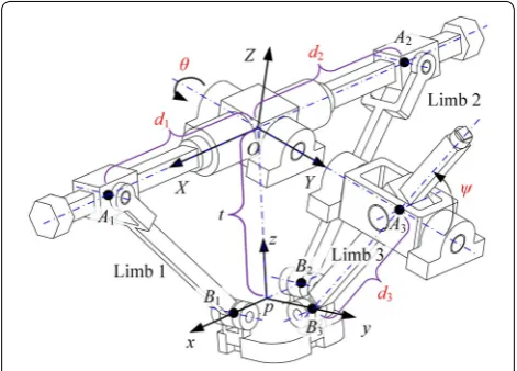
It is obvious that the constructed PMs have unlimited rotational capability around one axis, i.e., the coincident axis of the two U-joints in each mechanism. In contrast, the rotational range around the other axis can also be considerably large, which is proved in this section by taking the 2-UPRR/UPR mechanism as an example. As shown in Figure 5, the mechanism has three limbs; limb 1 and limb 2 are UPRR type limbs and share a common U-joint, and limb 3 is a UPR type limb. The central points of the P pair and the first R pair in limb 1 (limb 2) are coincident, and these points are denoted by A1 (for limb 1) and A2 (for limb 2) hereafter. The center of the U-joint in limb 3 is denoted by A3, and the centers of the three moving platform-connected R pairs are denoted by B1, B2, and B3, respectively.
There are several necessary geometrical conditions in the mechanism. The first rotational axes of the two U-joints (s1, s7) are coincident. In limb 1 and limb 2, the Table 5 UP‑equivalent PMs in group 1 in category5‑5‑4
{L1} = {L3} = {R(O, u)}{R(O, v)}{G(u)},{L2} = {R(O, u)}{G(v)}
2‑uvUkPRR/uvUvPR
2‑uvUkPRR/uvUvRP
2‑uvUkPRR/uvUvRR
2‑uvUkPRR/uRvPRR
2‑uvUkRRR/uvUvPR
2‑uvUkRRR/uRvPRR
2‑uvUkRRP/uvUvPR
2‑uvUkRRP/uvUvRP
2‑uvUkRRP/uvUvRR
2‑uvUkRRP/uRvPRR
2‑uvUkRRR/uvUvRP
2‑uvUkRPR/uvUvPR
2‑uvUkRPR/uvUvRP
2‑uvUkRPR/uvUvRR
2‑uvUkRPR/uRvPRR
2‑uvUkRRR/uvUvRR
Figure 3 Three UP‑equivalent PMs in subcategory 5‑5‑4
R pairs have parallel axes (s3, s4, s5, s6). In limb 3, the R pair has an axis (s9) parallel to line B1B2 and the second rotational axis (s8) of the U-joint within the same limb. The three P pairs (denoted by Pi for limb i) are equipped with motors. In addition, the rotation around axis s1 is also actuated. Thus, there are four inputs in total. In an initial configuration, as shown in Figure 5(a), s1 and s7 are parallel to s3, s4, s5 and s6. s8 and s9 are parallel to line B1B2 and the second rotational axis (s2) of the U-joint in limb 1. From this configuration, if we fix P3 as well as axis s1 of the U-joint and give P1 and P2 with different displace-ments, the mechanism will move to a configuration as in Figure 5(b), in which s2 is no longer parallel to s8, s9, and line B1B2. The mechanism degenerates into a 2-DOF mechanism with one rotational DOF around axis s1(s7) and a translational DOF. This is denoted by 1R1T con-figuration. In contrast, if we fix axis s1, P1, and P2 in the initial configuration, and give a displacement to P3, the mechanism will move to a configuration in Figure 5(c), in which s1 and s7 are not parallel to s3, s4, s5 and s6. The mechanism in this configuration has three DOFs, includ-ing two rotations around axes s1 and s2; this is called the 2R1T configuration. The rotational angle of s1 always equals that of s7, and the displacements of P1 and P2 are the same since limb 1 and limb 2 are designed to have identical dimensions. Therefore, if the mechanism is in the initial configuration, to prevent it from moving to the 1R1T configuration, P1 and P2 should be properly con-trolled to ensure that |OA1| = |OA2| (O is the center of the U-joint in limb 1). Thus, s2 will remain parallel to s8, s9, and line B1B2. The mechanism continues working in the 2R1T operation mode.
Next, the kinematic model of the mechanism is estab-lished. Here, we only focus on the 2R1T operation mode. A global coordinate system G(O-XYZ) is attached to the fixed base with its origin coincident with the central point of the U-joint in limb 1; axis Y is coincident with
the first rotational axis of the U-joint, which is connected to the fixed base; axis X is parallel to the horizontal plane and perpendicular to axis Y, and axis Z is defined accord-ing to the right hand rule, as in Figure 6. Similarly, a local coordinate system L(p-xyz) is attached to the moving platform with its origin located at the middle of line B1B2, axis x coincident with B2B1, axis y passing through point B3, and axis z defined according to the right hand rule.
The orientation of the moving platform can be expressed by a rotation around axis Y followed by a rota-tion around the resulting axis X’. Thus, the rotational matrix is given by
where α and β are rotational angles around axes Y and X′, respectively.
The position vector of point p expressed in the global coordinate system can be given by
where t denotes the distance between points O and p.
5.1 Inverse Position Solutions and Jacobian Matrix
The displacements of the three P pairs are denoted by d1, d2, and d3, and the rotational angle of the first axis of the U-joint in limbs 1 and 2 is denoted by θ, as in Figure 6. The inverse position problem is to find the values of d1, d2, d3, and θ with the moving platform parameters α, β , and t given. This is quite an easy problem and one can directly determine that θ equals α. We express the posi-tion vectors of points Ai (i = 1, 2, 3) in the global coordi-nate system as
(20) GR
L=RYRX=
cosα 0 sinα 0 1 0 −sinα 0 cosα
1 0 0 0 cosβ −sinβ
0 sinβ cosβ
=
cosα sinαsinβ sinαcosβ 0 cosβ −sinβ −sinα cosαsinβ cosαcosβ
,
(21) p=[tsinαcosβ, −tsinβ,tcosαcosβ]T,
where a represents the length of OA3. We have d1 = −d2 since P1 and P2 are properly actuated.
The position vectors of points Bi (i = 1, 2, 3) expressed in local coordinate system are given by
where the left superscript L denotes that the coordinates are expressed in the local system, m and n are dimen-sional parameters of the moving platform.
The vectors in Eq. (23) can be transformed into the global coordinate system using the following expression
Thus, we have
(22) A1= [d1cosθ, 0,−d1sinθ]T,
A2= [d2cosθ, 0,−d2sinθ]T,
A3= [0,a, 0]T,
(23) LB
1= [m, 0, 0]T, L
B2= [−m, 0, 0]T, LB
3= [0,n, 0]T,
(24) Bi=GRLLBi+p.
(25)
B1=
mcosα+tsinαcosβ
−tsinβ
−msinα+tcosαcosβ
,
B2=
−mcosα+tsinαcosβ
−tsinβ
msinα+tcosαcosβ
,
B3=
nsinαsinβ+tsinαcosβ
ncosβ−tsinβ
ncosαsinβ+tcosαcosβ
.
Three constraint equations are established as
where the constant l represents the length of link A1B1 and A2B2.
Substituting Eqs. (22) and (25) into Eq. (26) yields
Through Eq. (27), the input parameters can be easily solved given the output parameters α, β, and t.
Differentiating both sides of Eq. (27) with respect to time, and using the fact that θ˙= ˙α, a set of equations can be derived and rearranged into matrix form as
in which d˙ = [d˙
1, d˙2, d˙3, θ˙]T is a vector that represents the input joint velocities, x˙ = [α˙, β˙, ˙t]T represents the veloc-ities of the moving platform, and J is a 4×3 matrix as follows:
in which the detailed expressions of the elements are as (26)
|A1−B1| =l,
|A2−B2| =l,
|A3−B3| =d3,
(27) (mcosα+tsinαcosβ−d1cosθ )2+(tsinβ)2
+(−msinα+tcosαcosβ+d1sinθ )2=l2, (−mcosα+tsinαcosβ−d2cosθ )2
+(tsinβ)2+(msinα+tcosαcosβ+d2sinθ )2=l2, (nsinαsinβ+tsinαcosβ)2+(ncosβ−tsinβ−a)2
+(ncosαsinβ+tcosαcosβ)2=d32.
(28)
˙ d=Jx˙,
(29)
J=
J11 J12 J13 J21 J22 J23 J31 J32 J33 J41 J42 J43
,
J11=0,J12=0,J13=
t
m−d1,
J21=0,J22=0,J23=
t
d1−m,
J31=0,
J32= a(tcosβ+nsinβ)
a2+n2+t2−2ancosβ+2atsinβ,
J33= t+asinβ
a2+n2+t2−2ancosβ+2atsinβ,
5.2 Workspace and Singularity
Once the inverse kinematic model is established, the workspace of the mechanism can be determined by con-sidering some constraints imposed by joints and actua-tors. Since the mechanism has unlimited rotational capability around axis Y, α is fixed as zero without loss of generality, and only the ranges of β and t are evaluated. Table 6 lists the dimensional parameters of the mecha-nism. The constraints of workspace are given as
where ψ is the angle between A3B3 and axis Y, as shown in Figure 6. ψ is constrained in a reasonable region to avoid interference between links.
By searching the potential region for points that satisfy the conditions in Eq. (30), the workspace of the mechanism is numerically determined as in Figure 7(a). The range of t is determined by the stroke of the actuators mounted to P1 and P2. When P1 and P2 reach their maximum stroke, t has a maximum value of −216 mm, corresponding to the right boundary of the workspace. Figure 7(e) shows such a con-figuration. When P1 and P2 reach their minimum stroke, t has a minimum value of −349.08 mm, corresponding to (30)
160 mm≤d1,d2≤360 mm, 80 mm≤d3≤400 mm,
π/6≤ψ ≤5π/6,
Table 6 Architectural parameters
Parameter l a m n
Value (mm) 360 280 72 82
Figure 7 Workspace, singularity and rotational capability. a Workspace, b Singular configuration I, c Singular configuration II, d P1 and P2 reach their
the left boundary of the workspace. Such a configuration is shown in Figure 7(d). The upper and lower boundaries of the workspace are determined by the stroke of P3 and the angle constraint of ψ.
From Figure 7(a), we can see that rotational angle β is allowed over a considerably large range, varying from
−33° to 70°. Furthermore, when t is set to a constant value, the rotational capability is still very high. The ranges of β are −5.82°~63.89° and −25.85°~54.84° when t is fixed at −320 mm and −240 mm, respectively, as illus-trated in Figure 7(a), Figure 7(f), and Figure 7(g).
A main factor that limits the rotational capability of a parallel mechanism is the inherent singularity, which may appear in the workspace, and divide it into small pieces. Therefore, the singularities of the 2-UPRR/UPR mecha-nism should be considered. Singularities of a mechamecha-nism can be determined by judging the determinant of its Jaco-bian matrix [33]. For the redundantly-actuated mecha-nism studied here, the Jacobian matrix is a 4×3 matrix, but we can easily find that J1 = −J2 (J1 and J2 are the first and second rows of the Jacobian matrix J, respectively) since d1 = −d2 always holds. Therefore, the singularities of the 2-UPRR/UPR mechanism can be defined by the following expression
Using this expression, the singularities of the mecha-nism are found and displayed with the orange line in Fig-ure 7(a). We find that the singularities are not within the workspace, which means the high rotational capability of the mechanism will not be affected.
In fact, the determined singularities correspond to configurations when points O, A3, and B3 locate at a (31)
det(Jn)=0, Jn=
J11 J12 J13 J31 J32 J33 J41 J42 J43
.
common line. Two singular configurations are illustrated in Figure 7(b) and Figure 7(c). In these configurations, the moving platform can have an infinitesimal translation in the direction perpendicular to OA3, despite all the actua-tions being locked. In other words, any external force in this direction cannot be balanced by the actuate force/ torque. However, these singular configurations are not contained in the workspace since d3 and ψ exceed their permitted ranges.
6 Application
Parallel mechanisms have been successfully applied in the development of various machine tools [34–37]. It is believed that some of the proposed UP-equivalent PMs, which have compact structures and less joints in the limbs, have promising applications in this field. For exam-ple, by combining the 2-URPR/UPR PM and a 2-DOF translational gantry, a hybrid milling machine is devel-oped as in Figure 8. The machine has a tool mounted on the moving platform of the PM and can operate on com-plex surfaces by relying on the coordinated motions of the PM and the gantry. It has the same operational abil-ity as the Tricept and TriVariant robots. Furthermore, its parallel part has the advantages of high load capacity, high rotational capability, and no strict assembly require-ment, which is preferable in practice.
7 Conclusions
1. A new family of UP-equivalent PMs with high rota-tional ability and low requirements in terms of geo-metrical conditions is disclosed using displacement subgroup theory. The new architectures of UP-equiv-alent PMs do not contain spherical joints and have no strict assembly requirements; this has several benefits in terms of manufacturing cost and payload capability.
2. The high rotational capability of the proposed mech-anisms is verified by investigating a typical example. In contrast to the unlimited rotational capability around one axis, rotation around the other axis is allowed over a considerably wide range of −33° ~ 70°. The singular curve is not within the workspace, and thus does not affect the rotational capability of the mechanism.
Authors’ contributions
QCL and WY designed and conducted the research. XXC finished 3‑D models of the mechanisms. All authors contributed to the preparation of the manu‑ script. All authors read and approved the final manuscript.
Authors’ Information
Wei Ye, born in 1988, is currently a lecturer at Zhejiang Sci‑Tech University, China. He received his Ph.D. degree on mechanism design and theory from Beijing Jiaotong University, China, in 2016. His research interests include design and analysis of reconfigurable parallel mechanisms. E‑mail: wye@zstu.edu.cn
Qin‑Chuan Li, born in 1975, is currently a professor at Zhejiang Sci‑Tech University, China. He received his Ph.D. degree on mechanism design and theory from Yanshan University, China, in 2003. His research interests include mechanism theory of parallel manipulators and application. Tel: +86‑571‑ 86843686; E‑mail: lqchuan@zstu.edu.cn.
Xin‑Xue Chai, born in 1988, is currently a lecturer at Zhejiang Sci‑Tech University, China. She received her Ph.D. degree on mechanism design and theory from Zhejiang Sci‑Tech University, China, in 2017. Her research interests include mechanism theory of parallel manipulators and application. E‑mail: jxcxx88@163.com.
Acknowledgements
Supported by National Natural Science Foundation of China (Grant Nos. 51525504, 51475431), Zhejiang Provincial Natural Science Foundation of China (Grant No. LZ14E050005), and Science Foundation of Zhejiang Sci‑Tech University, China (Grant No. 16022091‑Y).
Competing interests
The authors declare that they have no competing interests.
Ethics approval and consent to participate Not applicable.
Publisher’s Note
Springer Nature remains neutral with regard to jurisdictional claims in pub‑ lished maps and institutional affiliations.
Received: 18 January 2017 Accepted: 14 January 2018
References
1. J Wahl. Articulated tool head: US, 6431802, 2002‑8‑13.
2. Y Q Zhao, Y Jin, J Zhang. Kinetostatic modeling and analysis of an Exechon parallel kinematic machine (PKM) module. Chinese Journal of Mechanical Engineering, 2016, 29(1): 33–44.
3. X W Kong, C M Gosselin. Type synthesis of three‑DOF up‑equivalent parallel manipulators using a virtual‑chain approach. Advances in Robot Kinematics, Dordrecht: Springer, 2006: 123–132.
4. J A Carretero, M Nahon, B Buckham, et al. Kinematic analysis of a three‑dof parallel mechanism for telescope applications. Proceedings of the ASME Design Engineering Technical Conferences, Sacramento, USA, September 14–17, 1997: DETC/DAC–3981.
5. Q C Li, J M Hervé. 1T2R parallel mechanisms without parasitic motion. IEEE Transactions on Robotics, 2010, 26(3): 401–410.
6. Q C Li, J M Hervé. Type synthesis of 3‑DOF RPR‑equivalent parallel mecha‑ nisms. IEEE Transactions on Robotics, 2014, 30(6): 1333–1343.
7. Q C Li, L M Xu, Q H Chen, et al. New family of RPR‑equivalent parallel mechanisms: design and application. Chinese Journal of Mechanical Engineering, 2017, 30(2): 217–221.
8. Q C Li, Q H Chen, X F Yu, et al. 3‑DOF parallel mechanism with two per‑ pendicular and non‑intersecting axes of rotation: CN, 201110357878.7, 2011‑11‑11. (in Chinese).
9. Y Jin, X W Kong, C Higgins, et al. Kinematic design of a new parallel kinematic machine for aircraft wing assembly. Proceedings of the IEEE 10th International Conference on Industrial Informatics, Beijing, China, July 25–27, 2012: 669–674.
10. Q C Li, W F Wu, J N Xiang, et al. A hybrid robot for friction stir welding. Proceedings of the Institution of Mechanical Engineers, Part C: Journal of Mechanical Engineering Science, 2015, 229(14): 2639–2650.
11. D Zhang, C M Gosselin. Kinetostatic analysis and design optimization of the tricept machine tool family. Journal of Manufacturing Science and Engineering, 2002, 124(3): 725‑733.
12. T Huang, M Li, X M Zhao, et al. Conceptual design and dimensional syn‑ thesis for a 3‑DOF module of the TriVariant‑a novel 5‑DOF reconfigurable hybrid robot. IEEE Transactions on Robotics, 2005, 21(3): 449–456. 13. M Li, T Huang, D G Chetwynd, et al. Forward position analysis of the
3‑DOF module of the TriVariant: A 5‑DOF reconfigurable hybrid robot. Journal of Mechanical Design, 2006, 128(1): 319–322.
14. J M Hervé. Analyse structurelle des mécanismes par groupe des déplace‑ ments. Mechanism and Machine Theory, 1978, 13(4): 437–450.
15. Q C Li, Z Huang, J M Hervé. Type synthesis of 3R2T 5‑DOF parallel mecha‑ nisms using the Lie group of displacements. IEEE Transactions on Robotics and Automation, 2004, 20(2): 173–180.
16. Q C Li, Z Huang, J M Hervé. Displacement manifold method for type synthesis of lower‑mobility parallel mechanisms. Science in China Series E: Technological Sciences, 2004, 47(6): 641–650.
17. J Angeles. The qualitative synthesis of parallel manipulators. Journal of Mechanical Design, 2004, 126(4): 617–624.
18. C C Lee, J M Hervé. Generators of the product of two Schoenflies motion groups. European Journal of Mechanics‑A/Solids, 2010, 29(1): 97–108. 19. C C Lee, J M Hervé. Translational parallel manipulators with doubly planar
limbs. Mechanism and Machine Theory, 2006, 41: 433–455.
20. J M Rico, J J Cervantes‑Sánchez, A Tadeo‑Chavez, et al. A comprehensive theory of type synthesis of fully parallel platforms. Proceedings of the ASME 2006 International Design Engineering Technical Conferences and Computers and Information in Engineering Conference, Philadelphia, USA, September 10–13 2006: 1067–1078.
21. J He, F Gao, X D Meng, et al. Type synthesis for 4‑DOF parallel press mechanism using GF set theory. Chinese Journal of Mechanical Engineer-ing, 2015, 28(4): 851–859.
22. Z Huang, Q C Li. General methodology for type synthesis of symmetrical lower‑mobility parallel manipulators and several novel manipulators. International Journal of Robotics Research, 2002, 21(2): 131–146. 23. Z Huang, Q C Li. Type synthesis of symmetrical lower mobility parallel
mechanisms using the constraint‑synthesis method. International Journal of Robotics Research, 2003, 22(1): 59–82.
24. X W Kong, C M Gosselin. Type synthesis of 3T1R 4‑dof parallel manipula‑ tors based on screw theory. IEEE Transactions on Robotics and Automation, 2004, 20(2): 181–190.
25. X W Kong, C M Gosselin. Type synthesis of three‑degree‑of‑freedom spherical parallel manipulators. International Journal of Robotics Research, 2004, 23(3): 237–245.
26. Y F Fang, L W Tsai. Structure synthesis of a class of 4‑DoF and 5‑DoF paral‑ lel manipulators with identical limb structures. International Journal of Robotics Research, 2002, 21(9): 799–810.
27. G Gogu. Structural synthesis of fully‑isotropic translational parallel robots via theory of linear transformations. European Journal of Mechanics‑A/ Solids, 2004, 23(6): 1021–1039.
28. M Carricato, V Parenti‑Castelli. Singularity‑free fully‑isotropic translational parallel mechanisms. The International Journal of Robotics Research, 2002, 21(2): 161–174.
30. M Carricato. Fully isotropic four‑degrees‑of‑freedom parallel mechanisms for Schoenflies motion. The International Journal of Robotics Research, 2005, 24(5): 397–414.
31. O Salgado, O Altuzarra, E Amezua, et al. A parallelogram‑based parallel manipulator for Schönflies motion. Journal of Mechanical Design, 2007, 129(12): 1243–1250.
32. O Altuzarra, B Şandru, C Pinto, et al. A symmetric parallel Schönflies‑ motion manipulator for pick‑and‑place operations. Robotica, 2011, 29(06): 853–862.
33. C M Gosselin, J Angeles. Singularity analysis of closed‑loop kinematic chains. IEEE Transactions on Robotics and Automation, 1990, 6(3): 281–290.
34. P Isabel, C E Sami, C Burkhard. Comparison of parallel kinematic machines with three translational degrees of freedom and linear actuation. Chinese Journal of Mechanical Engineering, 2015, 28(4): 841–850.
35. Y B Ni, B Zhang, Y Sun, et al. Accuracy analysis and design of A3 parallel spindle head. Chinese Journal of Mechanical Engineering, 2016, 29(2): 239–249.
36. Zhang D. Parallel robotic machine tools. New York: Springer Sci‑ ence + Business Media, 2009.