Dynamic model for sucking process of pneumatic cutting-type
safflower harvest device
Ge Yun
1,2,
Zhang Lixin
1*,
Qian Ying
1,
Jiao Xiaopan
1,
Chen Yuanbo
1 (1. College of Mechanical and Electrical Engineering, Shihezi University, Shihezi 832000, China;2. The State Key Laboratory of Mechanical Transmissions, Chongqing University, China)
Abstract: This study proposed a method using negative pressure sucking the petals adhered around cones. The structural parameters of the sucking device affect the flow-field distribution in the negative-pressure air chamber. In order to improve the harvesting efficiency and quality of the pneumatic cutting-type safflower harvest device, a dynamic model was established and the safflower petals upwind area were measured. According to the test, the size parameters of the thornless Yumin safflower were as follows: the average necking diameter was 6.30 mm, the average capitulum diameter was 20.89 mm and the average petal length was 22.39 mm. The measured maximum frontal area of the safflower petal was 11-40 mm2. Secondly, the
required negative pressure power that resulted in the rise of safflower petals was calculated. In general, when the suction of the negative pressure reaches 9.8 m/s, the safflower petals can be sucked successfully. The simulation of the flow field in the suction mouth indicated that the streamlined suction mouth was beneficial in reducing resistance and the test results of high-speed photography showed that the aforementioned condition could improve the efficiency of the upright safflower. And the test verified that the rate of the unshaped petals in the cylindrical air tunnel was low and the efficiency of carding and shaping under negative pressure was considerably better in wet petals than in dry ones. Results of the upright safflower petal experiment were consistent with the theoretical analysis and simulation conclusion, and indicated the precision of the dynamic model and suction flower mouth orifice-shaped simulation analysis.
Keywords: safflower petal, pneumatic harvest device, dynamic model, sucking process
DOI: 10.3965/j.ijabe.20160905.2139
Citation: Ge Y, Zhang L X, Qian Y, Jiao X P, Chen Y B. Dynamic model for sucking process of pneumatic cutting-type safflower harvest device. Int J Agric & Biol Eng, 2016; 9(5): 43-50.
1 Introduction
Safflower is an annual oil and medicine plant with a growth cycle of 120 d. Safflower seeds are primarily
Received date: 2015-09-15 Accepted date: 2016-05-16
Biographies: Ge Yun, PhD candidate, Associate Professor, research interests: agricultural machine engineering, Email: [email protected]; Qian Ying, Master student, research interests: harvesting machinery, Email: [email protected]; Jiao Xiaopan, Master student, research interests: agricultural mechanization and automation, Email: [email protected]; Chen Yuanbo, Master student, research interests: harvesting machinery, Email: [email protected].
*Corresponding author: Zhang Lixin, PhD, Professor, research interests: mechanical engineering. College of Mechanical and Electrical Engineering, Shihezi University, Xinjiang, China. Tel: +86-17709939016; Email: [email protected].
used for oil production, while safflower petals are used for extracting natural pigment and for medicinal purposes[1-3]. The safflower harvest period is generally from the end of June to the beginning of September. Currently, the safflower is mainly harvested by human hand, which is labor-intensive and inefficient, and even leading to lack of time for picking[1,4]. Therefore, the low efficiency of safflower petals has restricted the large scale development of safflower, and developing a mechanized harvesting system for safflower is urgently needed.
cones, increasing the difficulty of picking. The research and development of safflower harvester mostly are based on pneumatic or cutting harvest principle[6-9].
The cutting harvester harvests the safflower by using the tool rotary movement [8]. Accurately positioning the cutting side of the blade is difficult when cutting safflower petals. Consequently, these petals break easily, which decreases the efficiency and quality. The air-blast harvester uses a flower-sucking channel which is aligned with the safflower petals when harvesting. The fan of this equipment produces negative pressure in the airflow field. So the petals are separated from the cones using the flow field effect. However, harvest efficiency decreases and power consumption of the fan increases because the petals pile up.
The aforementioned two existing models are unable to yield a good harvest result; we proposed a method using negative pressure sucking the petals adhered around cones and then cutting them with the rotating tool. The harvesting process of the airflow pressure cutting combined safflower petal harvesters comprises three stages: 1) combing and shaping: safflower petals are combed and shaped to a vertical state by the action of negative airflow field pressure; 2) cutting: safflower petals are separated from the cones by rotary blade action; and 3) collecting and conveying: after separation, safflower petals are collected and conveyed to the storage room through the action of negative airflow field pressure.
This harvesting method can improve both the harvesting efficiency and quality of safflower petals. The structural parameters of the sucking device affect the flow-field distribution in the negative-pressure air room. With the airflow carding and shaping process as the study object, dynamic model of the safflower petals was established to analyze the carding and shaping mechanisms of the airflow field and the airflow change rule.
2 Materials and methods
2.1 Materials
In this study, the thornless Yumin safflowers were used along with varieties of oil-flower. Safflower had a height of 80-100 cm. The minimum length of the
branches of the plant was 35-40 cm. The entire flower ball of safflower reached 10-30 cm. The plant samples used in this study were provided by the Yumin County Technology Bureau Seed Station.
2.2 Parameters measurement methods
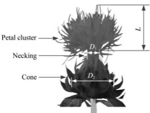
Figure 1 shows that safflower clusters are coronal in their natural state. With the decline of water content, the safflower petals wither and adhere around cones.
1st 2nd 3rd 4th 5th 6th
Figure 1 Forms of safflower after flowering in different days Referring to the standard NY/T1133-2006[10], 100 plants were marked. Then we selected three capitulums from the top, middle and lower positions of each plant at full-bloom period. Electronic digital display vernier caliper (precision: 0.02 mm) was used to measure the biggest diameters. The diameters of three sepals nearest to petals cluster were selected as the measurement positions, as shown in Figure 2. At last, the arithmetic mean values were calculated and took as the final result.
Figure 2 Diameter of the safflower capitulum
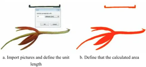
obtained projected area is the maximum frontal area of the safflower petals. The process of calculating[11-13] safflower petal length and area with Digimizer is shown in Figure 3.
a. Import pictures and define the unit length
b. Define that the calculated area
Figure 3 Process of calculating safflower lengths and areas with Digimizer
2.3 Efficiency measurement method
Figure 4 shows the combing and shaping device of safflowers including the positioning mouth of the safflower cones, suction fan, and airflow channel. When the machine works, the negative pressure fan rotates to generate air stream while the harvesting process is in progress. The coronal safflower petals reach the vertical state, carded, and shaped by the negative airflow pressure in the flower-sucking channel. The joints of the petals and cones are both exposed. The planetary gear transmission device drives the tool to cut following the motor rotation so as to separate the petals and cones. The petal cuts are conveyed to the storage room of flowers by means of the negative pressure action. The airflow discharges backward and the petals are left in the storage room of flowers. This process can separate gas and solid, and complete the conveying and collecting of the safflower petals.
Note: 1. Negative pressure fan 2. Filtration system 3. Collection device 4. Air tunnel 5. Motor 6. Planetary gear train 7. Fruit positioner 8. Cutting tool 9. Shell 10. Handle
Figure 4 Working principle diagram of the safflower petal harvest device
In the same working condition, both the structural parameters of the airflow passage and the distribution of the internal airflow field are different[14-15]. Therefore, the structural parameters of the combing and shaping device and the selection of the suction fan are crucial factors that affect the efficiency and quality of the process[16-19].
At standard atmospheric pressure,the air density is 1.2 kg/m3[20]. The calculation of the airflow field Reynolds number is Re=18665.2>2300 in the flower suction nozzle of the carding and shaping device where the safflower petals are placed. Therefore, the airflow field of the carding and shaping device is identified as the turbulence when the device is working.
The working flow of the pressure source is 310 m3/h, while the airflow inlet diameter of the carding and shaping device is 20 mm. At normal temperature, the specific heat ratio of the gas is K=1.4, the gas constant is
R=287 J/kg·K, the absolute temperature is T=293 K. Whether the gas can be compressed is judged through the Maher coefficient Ma, which is calculated as below Equation (1):
2
a
M
KRT
υ
= (1)
where, V is the fluid velocity, m/s; K is the gas specific heat ratio; R is the gas constant, J/kg·K; T is the gas constant in K.
Mach number Ma=0.13<0.3 is obtained by calculating the Maher coefficient; thus, gas can be calculated in an incompressible way.
Figure 5 shows the equipment and systems used in this study, including a Canadian CPL-MS70K-speed camera, fan, clamping device, image display, and processing system.
being carded and shaped was recorded using the high-speed photography system. Then, the frames from the original to the final state were observed and recorded. Therefore, the time required for carding and shaping the safflower petals can be calculated.
Figure 5 Safflower petals upright test system
3 Results
Table 1 shows the parameter data of the safflower. The average necking diameter is 6.30 mm. The average capitulum diameter is 20.89 mm and the average petal length is 22.39 mm.
Table1 Measured results of the dimension parameters
Test parameters Parameter values
Max Min Ave. Stand CV Necking diameter D1/mm 6.98 5.54 6.30 0.41 6.5 %
Fruit ball diameter D2/mm 23.66 17.01 20.89 1.94 9.3 %
Petal length L/mm 28.49 15.75 22.39 3.41 15.2 %
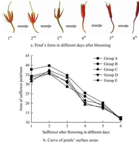
Figure 6 shows the filaments change process of surface area and moisture content changes are consistent. The data measured are analyzed by using statistics method. The maximum frontal areas of the safflower petals are between 11-40 mm2. In the process of carding and shaping, from the center to the outer edge of the corolla, safflower gradually achieves the vertical state from the natural state, the data of specific test results are listed in Table 2.
Based on the above experiment, the safflower petals gradually transform from the natural state to the upright state. A contrast test shows that the number of unshaped petals is less in the cylindrical air tunnel; the time required for carding and shaping the petals is also considerably shorter in this tunnel than in the cylindrical
pipe. These results are consistent with the previous theoretical analysis and flow field simulations. Therefore, the transverse velocity gradient flow field is obtained by opting for the shrinkage pipe to design the suction channel.
1st 2nd 3rd 4th 5th 6th
a. Petal’s form in different days after blooming
b. Curve of petals’ surface areas
Figure 6 Petals’ surface areas and forms in different days after blooming
Table 2 Experimental results of carding and shaping
Test parameters
Cylindrical tube Contraction tube
Fresh flower
Dried flowers
Fresh flower
Dried flowers Finishing carding and shaping
average time/s 0.47 1.24 0.12 0.17 Mass of safflower sorted out/g 0.301 0.221 0.375 0.34 Mass of plastic not combed/g 0.044 0.035 0.005 0.016 Carding and shaping rate/% 87.25 86.33 98.68 95.51
4 Discussion
4.1 Stress analysis of safflower in the airflow
significantly shorter than the characteristic scale of the airflow field. Therefore, the motion of every safflower petal can be regarded as a Stokes flow.
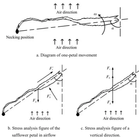
With the vertical upward airflow of the negative pressure fan in the carding and shaping process, the safflower petals from the static state in the flow field rotate, rise, and erect around the fulcrum of the necking, as shown in Figure 7a. The trajectories, spatial distribution, and orientation distribution of safflower petals in the flow field depend on the forces and moments acting on these petals, the stress analysis of the safflower petal in airflow is shown in Figure 7b. The flow around resistance forces F′r,air buoyancy F′b acting on the petal and gravity Fg. According to reference[14], they can be
calculated as Equations (2)-(4):
2
1 2
r t f
F′ = CAρ υ (2)
where, At is the frontal area, m2; υ is the relative velocity
between the air and safflower petals, m/s; C is the air resistance coefficient; ρf is the air density, kg/m3; α is the
attitude angle, (°), which is the angle between the axis of the safflower petals and the axis vertical to the ground.
b f
s
m
F ρ g
ρ
′ = (3)
g
F =mg (4)
where, ρs is the safflower petal density, kg/m3; m is the
safflower petal mass, kg; g is the acceleration caused by gravity, m/s2.
4.2 Critical starting speed of the safflower petals during carding and shaping
When the average wind speed has a critical value under the negative pressure flow, the safflower petals break away from the static state by means of the negative pressure to achieve upward acceleration. Figure 7 illustrates that the sum of the upward force of the safflower petals is higher than that of the downward force. Where the vertical direction forces of the safflower petal in airflow is the Fr, Fb and Fg. They are expressed as
Equations (5) and (6):
2
1
sin 2
r t f
F = CAρ υ α (5)
cos
b f
s
m
F ρ g α
ρ
= (6)
a. Diagram of one-petal movement
b. Stress analysis figure of the safflower petal in airflow
c. Stress analysis figure of a vertical direction.
Figure 7 Force analysis diagram of the safflower petal in airflow during upright process
Their relationship is represented as Equation (7):
r b g
F +F >F (7)
When the materials are at a critical speed of suspension or deposition, Equations (4)-(6) are substituted into Equation (7) based on the aerodynamic principle. The boundary conditions are as Equation (8):
2
1
cos sin
2
f t f
s
m
mg ρ g α CAρ υ α
ρ
= + (8)
Therefore, the critical speed υt of the safflower petals
is calculated by Equation (9):
2 ( cos ) sin
s f
t
t s f
mg A C
ρ ρ α
υ
ρ ρ α
−
= (9)
From Equation (9), the critical velocity of the safflower petals is inversely proportional to the air resistance coefficient and frontal area.
The frontal area of the safflower petals is the projection area of these petals in the direction perpendicular to the relative velocity that are directly related to the attitude angle (Figure 7). The relationship between actual frontal area and maximum frontal area is shown in Equation (10):
sin t
A A
α
= (10)
area of the safflower petals.
The natural attitude angles of the safflower petals related to their maturity are typically between 0°-160°. Safflower petals are slender and their surface structures are also different depending on maturity levels. The surface structures of these petals are far from the sphere; thus, they cannot be handled by an equivalent sphere.
The maximum frontal area of the safflower petals are between 11 mm2 and 40 mm2. Based on standard atmospheric pressure using hydrodynamics, the split point of the boundary layer is stable when the pressure is 103≤Re≤2×10⁵; the drag coefficient C is substantially constant with a value of approximately 0.44.
The petal quantity of a single safflower is between 0.121-0.456 g, while the density is between 120-196 kg/m3. Calculation using Equation (9) shows that the critical speed is between 19.29-19.8 m/s.
4.3 Relationship between gas velocity and cross-section area of the flow channel
The safflower petals can obtain different motion characteristics when the structural parameters of the channel are altered under the same negative pressure power. This study opts for the flow field in the circular tube and contract. The effects of the velocity gradient when the safflowers move in the flow field, as well as the orientation distribution of the petals, were compared.
Negative pressure generated by the fan is sent directly to the safflower petals through the absorption channel. Therefore, the flow-field distribution inside the absorption channel directly affects the efficiency and effectiveness of the safflower petals in the sucking processes. The cross-section of the absorption channel under the same negative pressure is generally different; the distribution of its internal flow field is also different. These differences result in the safflower petals acquiring different moving properties. The commonly used cross-sectional shapes have a cylindrical, shrinking, and intestinal tubular. The relationship between the gas velocity and cross-sectional area of the flow channel can be analyzed using the formula for the fan flow rate.
The fan flow rate, which is the product of wind speed and cross-sectional area of the wind tunnel, is expressed in Equation (11):
j
Q= ⋅υ A (11)
where, Q is the fan flow rate, m3/s;υ is the gas velocity, m/s; Aj is the cross-sectional area of flow channel, m2.
When the fan flow rate is consistent, the flow obtains an accelerated motion along the streamline and its cross-sectional area of flow must be gradually reduced. The absorption channel should also be a shrinking tube to obtain a gradient flow field of transverse velocity, thereby resulting in the safflower petals turning from static to critical starting. The carding and shaping of safflower petals will be achieved under the action of gas flow.
The flow field of contraction refers to fluid flowing into a wide mouth and flowing out of a narrow one. Table 1 presents the detailed parameters of the structure. The inlet flow size of the flower channel is slightly larger than the maximum value of the safflower diameter D2 (25 mm). The outlet size is the maximum value of the necking diameter D1 (7 mm). Although the pipeline length is slightly longer than the maximum petal length L, with the value of 30 mm, the conical angle of the shrinkage cast is 34°.
4.4 Simulation for airflow velocity changed result
Airflow velocity is the primary factor that affects the movement efficiency of the safflower petal carding and shaping in the suction mouth. This condition determines the value of airflow force on the safflower petals. Based on the analysis, the suction mouth alters the flow type and airflow velocity. This study simulated and analyzed the relationship between the flow type and the airflow velocity using fluid analysis software.
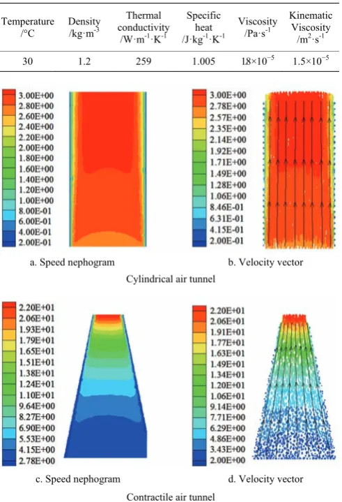
Table 3 presents the natural characteristics of air, including flow density, viscosity, specific heat, and conductivity when the simulation was conducted using fluid analysis software. According to stability analysis, the flow type is incompressible and the airflow field is turbulent. The initial velocity of the suction mouth reached 19.8 m/s, which was the critical velocity of the safflower petals.
airflow velocity, fan power should be increased to make the safflower petals proceeding to the airflow direction. However, this process leads to extensive power consumption and prevents a good result in carding and shaping the safflower petals.
Table 3 Parameters of air simulation design
Temperature /°C
Density /kg·m-3
Thermal conductivity /W·m-1·K-1
Specific heat /J·kg-1·K-1
Viscosity /Pa·s-1
Kinematic Viscosity
/m2·s-1
30 1.2 259 1.005 1.8 × 10⁻⁵ 1.5× 10⁻⁵
a. Speed nephogram b. Velocity vector Cylindrical air tunnel
c. Speed nephogram d. Velocity vector Contractile air tunnel
Figure 8 Flow field simulation of the suction tunnel Combined with the shape of the safflower fruit, the reduction angle of the shrinkage pipe is set as 34° based on fluid dynamics. Figure 8c and 8d illustrate the results of the flow field simulation. A gradient of the velocity was observed with an outlet velocity of approximately 160 m/s. The kinetic energy reached the maximum level because of the velocity coefficient in the pipe. The safflower petals can easily exceed the critical velocity under the action of airflow; thus, the carding and shaping become faster and better.
Based on the preceding analysis, the results of the flow field simulation are consistent with the conclusions of the theoretical analysis. Therefore, with the large opening inflow and structure outflow, the shrinkage pipe
is more suitable for carding and shaping the safflower petals.
5 Conclusions
1) The dynamic model for safflower petals carding and shaping was established in this study. Under normal conditions, this model proved that the air pressure had a direct relationship with the air resistance coefficient, frontal area, and quadratic in velocity. Therefore, the reduction angle opposite the corolla could decrease the frontal area of the safflower petals. In general, when the suction of the negative pressure reached 9.8 m/s, the safflower petals carding and shaping could be successfully completed and it could prepare the best posture for cutting separation.
2) According to the test results, average size parameter values of the thornless Yumin safflower were as follows: the average necking diameter was 6.30 mm, the average capitulum diameter is 20.89 mm and the average petal length was 22.39 mm. The measured maximum frontal area of the safflower petal was 11-40 mm2.
3) The finite element model of the airflow field in the suction mouth was established by conducting a simulation of the flow field in the suction mouth. The results indicated that the streamlined suction mouth was beneficial in reducing resistance. The bench test verified that the rate of the unshaped petals in the cylindrical air tunnel was low and the efficiency of carding and shaping under negative pressure was considerably better in wet petals than in dry ones.
Acknowledgements
This work was supported by the State Key Laboratory of Mechanical Transmission Open Fund (No. SKLMT-KFKT-201502), the National Natural Science Foundation of China (No. 51565050), and the High-tech Research Project of Xingjiang, China (No. 201511107).
[References]
[1] Wang Z M, Chen Y H. Safflower. Beijing: Chinese Medicine Press, 2001. pp. 26–39. (in Chinese)
yields of safflower in summer planting, local variety of Isfahan, Koseh. Journal of Science & Technology of Agriculture & Natural Resources, 2005; 9(3): 131–142. [3] Dashti S, Alahdadi I, Behbahani S M R, Nazarifar M H.
Zoning and quantitative evaluation for safflower. Asian Journal of Agricultural Sciences, 2012; 4(6): 373–378. [4] Mc Guire P E, Damania A B, Qualset C O. Safflower in
California. The Paulden F. Knowles personal history of plant exploration and research on evolution, genetics, andbreeding. Agronomy Progress report No.313, Dept. of Plant Sciences. University of California, Davis, CA, USA, 2012.
[5] Guo M L, Zhang Z Y, Zhang H M, Su Z W. Effects of collecting time and processing methods on the quality of safflower crude drug. Acad J Sec Mil Med Univ.1999; 20(8): 535–537. (in Chinese with English abstract)
[6] Rajvanshi A K. Development of safflower petal collector. Vith International Safflower Conference, İstanbul-Turkey, 6-10 June, 2005. Safflower: A Unique Crop for Oil Spices and Health Consequently, A Better Life for You. 2005; 2.4, 80–85.
[7] Azimi S, Chegini G, Kianmehr M H, Heidari A. Design and construction of a harvesting safflower petals machine. Mechanics & Industry, 2012; 13(5): 301–305.
[8] Ge Y, Zhang L X, Han D D, Chen J P, Fu W. Current state and development trend of the mechanical harvesting on saffron filaments. Journal of Agricultural Mechanization Research, 2014; 36(11): 265–268. (in Chinese with English abstract).
[9] Antonelli M G, Auriti L, Zobel P B, Raparelli T. Development of a new harvesting module for saffron flower detachment. The Romanian Review Precision Mechanics Optics & Mechatronics, 2011; 39: 163–168.
[10] National Agricultural Machinery Standardization Technical Committee of Agricultural Mechanization. NY/T1133-2006 Job quality cotton picker. Beijing: China Agriculture Press. 2006. (in Chinese)
[11] Shahbazi F, Galedar M N, Taheri-Garavand A, Mohtasebi S S. Physical properties of safflower stalk. International Agrophysics, 2011; 25(3): 281–286.
[12] Viswanathan R, Pandiyarajan T, Varadaraju N. Physical and mechanical properties of tomato fruits as related to pulping. Journal of Food Science and Technology, 1997; 34(6): 537–539.
[13] Li Z G, Li P P, Liu J Z. Physical and mechanical properties of tomato fruits as related to robot’s harvesting. Journal of Food Engineering, 2011; 103(2): 170–178.
[14] Xia H M, Li Z W, Wang L Y. Research on suction species dynamic model of pneumatic suction plate vegetable seed metering device. South China Agricultural University, 2011; 32(1): 112–116. (in Chinese with English abstract)
[15] Singh R C, Singh G, Saraswat D C. Optimisation of design and operational parameters of a pneumatic seed metering device for planting cottonseeds, 2005; 92(4): 429–438. [16] Karayel D. Performance of a modified precision vacuum
seeder for no-till sowing of maize and soybean. J Soil Till Res, 2009; 104(1): 121–125.
[17] Hayashi S, Shigematsu K, Yamamoto S, Kobayashi K, Kohno Y, Kamata J, et al. Evaluation of a strawberry-harvesting robot in a field test. Biosystems Engineering, 2010; 105(2): 160–171.
[18] Sui R X, Thomasson J A, To S D F. Cotton-harvester-flow simulator for testing cotton yield monitors. Int J Agric & Biol Eng, 2010; 3(1): 44–49.
[19] Singh R C, Singh G, Saraswat D C. Optimisation of design and operational parameters of a pneumatic seed metering device for planting cottonseeds. Biosystems Engineering, 2005; 92(4): 429–438.
[20] Zhang Y C. Hydrodynamics. Beijing: Higher Education Press. 2007. pp. 398–421. (in Chinese).
[21] Wang J K, Guo K Q, Lü X M, Jiang B, Li B. High-speed photography analysis on improved clamping dibbler for cotton. Transactions of the CSAM, 2011; 42(10): 74–78. (in Chinese with English abstract).
[22] Thurner P J, Erickson B, Jungmann R. High-speed photography of compressed human trabecular bonecorrelates whitening to microscopic damage. Engineering Fracture Mechanics, 2007; 74(12): 1928–1941.