Improving the performance of mechanical stirring in biogas plant
by computational fluid dynamics (CFD)
Rashed Mohammadrezaei, Samira Zareei, Nasser Behroozi-Khazaei
(Department of Biosystems engineering, University of Kurdistan, Sanandaj, Iran)
Abstract: Stirring of material in biogas plant needs to be done to provide desirable contact between microorganisms and substrate which can improve digestion process. In the present study, computational fluid dynamics (CFD) was used to determine a suitable mechanical stirrer for biogas plant and simulate the flow pattern of cow manure. In order to select optimum design of impeller, three types of impeller including six-blade turbine, four-blade turbine and six-flat-blade disc turbine were evaluated. Simulations were undertaken utilizing Fluent 15.0 software with a multiple reference frame approach via standard k-ε turbulence model under steady-state conditions. According to the simulation results, six-blade turbine impeller is more appropriate than the two other impellers. The results further indicated that, this type of stirrer offers suitable mixing both at the center and on the lateral walls of the reactor, reducing dead spaces and improving mass and heat transfers inside the reactor.
Keywords: anaerobic digestion, cow manure, flow pattern, simulation, stirred tank
Citation:Mohammadrezaei, R., S. Zareei, and N. Behroozi-Khazaei. 2017. Improving the performance of mechanical stirring in biogas plant by computational fluid dynamics (CFD). Agricultural Engineering International: CIGR Journal, 19(4): 91–97.
1 Introduction
Biogas is a renewable energy source that is produced
through anaerobic digestion of organic waste. The
production of biogas is influenced by many operational
parameters, including temperature, pH, stirring, organic
loading rate, hydraulic retention time, etc. (Yadvika et al.,
2004; Shen et al., 2013). Stirring is an important
operation that homogenizes anaerobic bacteria, nutrients,
and temperature throughout the reactor to maximize
biogas production. The importance of mixing in
achieving efficient substrate conversion has been reported
by several researchers (McMahon et al., 2001; Stroot et
al., 2001; Kim et al., 2002; Karim et al., 2005; Vavilin
and Angelidaki, 2005; Vedrenne et al., 2008). Various
methods have been proposed to undertake mixing
operation within biogas reactors. Mechanical mixing,
Received date: 2017-01-04 Accepted date: 2017-05-17 * Corresponding author: Samira Zareei, Department of Biosystems Engineering, University of Kurdistan, Pasdaran street, Sanandaj, Iran. Postal code: 66177-15177. Email: s.zareei@ uok.ac.ir
spargers and jets are common choices for stirring
purposes (Kapraju et al., 2008;Karim et al., 2005).
Considering the variety of the processes and different
purposes in which they are serving, stirrers have been
developed with a large number of different geometries.
Mechanical stirring represents one of the most efficient
and inexpensive mixing methods. Although the
significance of the mixing to achieve optimal process
performance and biogas production is well known, an
obvious agreement on a single optimal mixing regime is
yet to be achieved. In-reactor mixing and contacting can
be undertaken in a continuous and alternating way.
Adequate mixing is important to minimize capital and
operating costs, enhance process efficiency when mass
transfer is limited, and hence increase overall profitability.
The efficiency of the stirring process using a mechanical
stirrer depends on the corresponding Reynolds number to
the impeller for both laminar and turbulent flow regimes.
The main mixing mechanism includes physical
movement of materials among various parts of the entire
body driven by the impeller rotating force. Successful
related to the way the fluid is stirred and mixed. Mixing
refers to the stirring of one or more non-similar materials
to obtain physical and chemical uniformity. Since
diffusivity in a liquid is very limited, mixing of liquids is
principally performed by stirring the liquid inside a tank.
Optimal design of stirrer and mixing operation efficiency
represent important factors for production quality and
production costs. The flow pattern in stirred tanks is a
complex phenomenon as there is a turbulent rotational
flow within a zone around the impeller.
In recent years, computational fluid dynamics (CFD)
methods have been increasingly substituted to empirical
experiments for the evaluation of flow fields and optimal
flow pattern as well as impeller and tank geometries
(Shekhar and Jayanti, 2002). CFD is a technique utilized
to analyze systems including fluid flow, heat transfer and
associated phenomena such as chemical reactions based
on computer-aided simulations (Dehghani, 2008). Being a
powerful methodology, CFD covers a wide spectrum of
industrial and non-industrial applications. Mechanical
stirred-tank reactors are widely used in industries
working with multi-phase systems. Numerous industrial
applications have been reported for these reactors (Nigam
and Schumpe, 1996). In 2010, Shirmohammadpour et al.
(2010) investigated the mixing inside a multiple-impeller
industrial reactor equipped with three marine impellers,
using CFD modeling technique. Li et al. (2004) studied
hydrodynamic behavior of a stirred tank equipped with a
curved-shaped stirrer. Their results showed that CFD
simulation can be used to properly predict radial and axial
velocities. Ahmed et al. (2010) studied different flow
configurations in a stirred-tank gas-liquid reactor
equipped with two Rushton type turbine stirrers. Ding et
al. (2010) showed that the type and rotating speed of the
impeller affect the resulting flow pattern significantly,
and proposed optimal impeller for bio-hydrogen
production accordingly. A comparison between
simulation results and experimental data indicated,
clearly, that the optimized impeller could achieve better
velocity distribution within the reactor at lower velocities
(Ding et al., 2010). Numerous factors affect the modeling
of stirred-tank reactors including adequate meshing
density, spatting methods, blade rotation model, and
finally, the fluid turbulence model, to name the most
important ones. In spite of the fact that much research has
been done on the mixing strategy in anaerobic digesters, a
clear image of the effects of the mixing in anaerobic
digestion in manure is not provided yet. Therefore,
stirring systems are still an important component of
biogas plants (Stroot et al., 2001; Karim et al., 2005). In
another research, CFD was used to investigate different
modes of mixing and consumed power in single and
multiple digesters. Cow manure and silage maize were
used as the reactor feed, with the stirred reactor serving as
the digester. The results indicated that the so-called
standard k-ε model outperformed other turbulence models
(Zhang et al., 2016).
The effect of mixing on anaerobic digestion from
manure was investigated at laboratory and pilot scales at
55ºC, wherein the effects of three mixing modes, namely
continuous, alternating and minimized mixings, were
studied and it was found that the mode and intensity of
mixing affect anaerobic digestion of manure. The results
of the research on pilot scale indicated a 7% increase in
biogas performance in alternating mixing approach as
compared to that of the continuous mixing approach
(Kaparaju et al., 2008). In a 1.5 m3 reactor fed by cow
manure, effects of continuous and alternating mixing on
biogas production performance were investigated at the
controlled temperature of 37ºC and for retention times of
10 and 20 days. The results revealed that, when the
retention time was set to 10 days, the rate of backflow
was of slight effect on the biogas production, with the
continuous backflow failed to improve the reactor
performance. Moreover, backflow was found to be of no
effect on the reactor performance for the retention time of
20 days (Rico et al., 2011).
The aim of present study is to select of proper
impeller design for mixing cow manure in a batch reactor
using CFD.
2 Materials and methods
This study was carried out to design proper stirrer for
a full-scale pilot biogas plant (1200 L) built at the
Biosystems Engineering Workshop, University of
operated with a working volume of 800 L. Fresh cow
manure was considered as substrate for the biogas plant.
Effective stirring of fluids to provide adequate mixing
and movement requires an extensive analysis of capacity,
viscosity, and dynamic response of the fluid, so that
based on the results of such an analysis one can obtain the
corresponding stirrer’s power and shaft speed as well as
blade size to the considered conditions.
2.1 Design of impeller
In order to select proper turbine stirrer, the
corresponding impeller system should be designed
properly. Further, the impeller design is in such a way
that the applied shear stress to the fluid is reduced to keep
the bacteria inside the reactor from being eliminated. The
design encompasses the type of turbine, number of
turbines, location-within-the-assembly of the blade and
its diameter. For this purpose, three types of impeller
were designed in the Solidworks software, on which
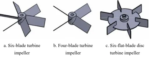
geometry the proceeding analyses were based. Figure 1
shows three types of impeller designed including
six-blade turbine impeller, four-blade turbine impeller,
and six-flat-blade disc turbine impeller with a radius of
10 cm. As can be seen on the following figure, in these
stirrers, a set of flat blades at a pitch angle of about 45°
producing an inter axial-radial flow were used. This
contributed into enhanced stirring as well as mass and
heat transfer. Pitched blades are often used in bio-reactors
which are sensitive to shear stress.
a. Six-blade turbine impeller
b. Four-blade turbine impeller
c. Six-flat-blade disc turbine impeller
Figure 1 A view of the three types of designed impeller
The stirrers are commonly used in non-continuous
reactors, although those can be used in continuous stirred
tank reactors (CSTR) as well (Li et al., 2004; Mirro and
Voll, 2009). The ratio of blade diameter to reactor
diameter (d/D) is an important parameter because it
affects flow pattern and power input and consequently
mixing efficiency. d/D values of 0.3-0.5 have been
studied and used in design and operation of conventional
stirred tanks. Table 1 provides the geometrical
dimensions for the designed impellers.
Table 1 Geometrical dimensions of the designed impellers
Type of impeller
Blade length,
cm
Blade width,
cm
Blade thickness,
cm
Blade angle, deg
Disc diameter,
cm
six-blade turbine impeller 13 5 0.2 45 - four-blade turbine impeller 13 5 0.2 45 -
six-flat-blade disc turbine
impeller 7 5 0.2 - 30
2.2 Power properties
As an important principle in choosing appropriate
stirring system, consumed power by mixing process is
largely dependent on the mixing intensity and fluid flow
conditions. The required power to achieve a desired
stirring speed depends on the frictional force and fluid
movement form against the impeller rotational resistance,
with the friction and fluid movement form resulted in the
development of some torque on the shaft of the stirrer.
Input power of a stirrer can be empirically calculated by
measuring the torque (T) (Shirmohammadpour et al.,
2010).
2.3 Relation between impellers’ power and speed for
mixing
When designing any impeller-driven mixing system, a
reasonably accurate estimation of the power/speed curve
is necessary for the selection of the power unit by which
the expected mixing performance can be provided.
Therefore, choosing an appropriate power unit may incur
high purchasing costs or increase the probability of
failure due to overloading operations. However, required
information can be acquired via full-scale experiments,
based on which information one will be able to undertake
the best design strategy (Cumby, 1990; Dickey, 2001).
Power consumption of stirrer can be evaluated from
Equation (1).
P = 2 πNiT (1)
where, P denotes the stirrer power (W); T is stirrer torque
(N.m), and Ni refers to the stirrer speed (rpm). When
more than one fluid is stirred mechanically,
corresponding Reynolds number (NRe) is defined as in
Equation (2).
2
i i
Re
ρD N N
μ
where, Ni and Di denote rotation speed (rpm) and
diameter of impeller (m) and ρ is the fluid density
(kg m-3). Moreover, μ represents the fluid viscosity (Pa s)
at each shear rate which can be calculated form Equation
(3).
s i
γ=k N (3)
where, ks is the consistency coefficient (Pa sn), and γ is
shear rate (s-1). Power number (Np) (dimensionless
number) and flow number (NQ) in stirred tanks can be
obtained using Equation (4) and (5).
3 5
P
i i
P N
ρN D
= (4)
3
Q
i i
Q N
N D
= (5)
NQ is the flow number (dimensionless number) and Q
refers to the flow rate (m3 sec-1). For turbines NQ is
calculated as 0.7- 2.9.
In present study, an electric motor with a power of
0.75 kW and a maximum rotational speed of 1400 rpm
and a gearbox with transmission ratio of 1:10 for
increasing stirrer torque, was used to provide the required
driving power for six-blade turbine stirrer.
2.4 CFD method
Fluent 15.0 software package was utilized in the
present study. Single phase model was used for the
simulations in this research, so as to reduce
computational costs of the system. In this model, the solid
particles together with liquid phase are taken as a single
homogeneous phase of the density and viscosity of the
solid-liquid mixture. In cases where volumetric percent
load of the solid particles is close to that of the fluid in
the reactor, one can use the so-called pseudo-single phase
model. Furthermore, the smaller the size of solid parties
and the lower the density difference between solid and
liquid phases, the more reasonable would be the use of
the pseudo-single phase model. Because in this case the
two-phase mixture of liquid and solid, homogeneous and
its behavior is very close to the behavior of a single-phase
mixture. Density and viscosity of the cow manure diluted
with water were considered as 1000.36 (kg m-3) and
0.070 (Pa s), respectively (El-mashad et al., 2005), with
the volumetric percent of the phases being 50% for either
of the liquid and solid phases (Wu, 2010). As such,
pseudo-single phase model was used to lower
computational costs. Indeed, the considered system is a
single-phase stirred-tank reactor. The reactor contained a
liquid (slurry). Performing a CFD simulation
encompasses several stages including pre-processing,
model start-up, calculation iteration, and post-processing
of the results. Entire calculation domain was decomposed
into several sub-domains among which, the impeller
sub-domain, as moving zone, was the only one that was
modeled using Tet/Hybrid meshing. The model start-up is
briefly described in the following:
•
Defining a three-dimensional, steady, implicitand pressure-based solver,
•
Defining a turbulence model from the panel ofviscous model,
•
Activating the fluid properties with theconditions of turbulent flow using the text command:
definition / models / viscous / turbulence model,
And then defining the material
•
Defining operational conditions by activatingthe gravity,
•
Defining boundary conditions,•
Adjusting the value of rotation speed anddirection and determining the rotating regions using the
rotating reference frame model at a given rotation speed,
•
Determining the zero normal gradient for allvariables at the liquid surface (symmetry boundary),
•
Flow fields Initialization,•
Activating the monitoring of residuals andsurface monitoring for an instance of the impeller’s
blades (torque),
•
Solving flow fields until achieving aconvergence,
•
Set the time step size.2.4.1 Meshing, boundary conditions and solving model
The considered system was a stirred-tank reactor with
an incomplete conical bed of 100 cm in diameter and
150 cm in height. The reactor per time was simulated
with one of three mentioned impeller. The stirrer had its
axis at the center of the reactor, with two impellers along
the axis at a distance of 50 cm from one another and
Tet/Hybrid meshing was used to mesh the system.
Combining structured meshes with unstructured ones, the
meshing approach is commonly used for complex
geometries. In addition, in order to verify the
independence of the results from the number of meshes,
in each simulation round, the existing meshing became
smaller before relaunching the simulation. No-slip
boundary conditions were applied on the walls. In order
to discretize the governing equations the system, QUICK
approach was followed, with the resulting discrete
equations solved by using SIMPLE algorithm. The
governing equations were solved via finite volume
method for the entire computational domain of the system,
and rotating frame model was utilized to simulate
rotational behavior of the stirrer. In this method, the
computational domain is decomposed into two zones:
rotating zone and stationary zone. All simulations were
undertaken three-dimensionally, considering steady-state
conditions.
3 Results and discussion
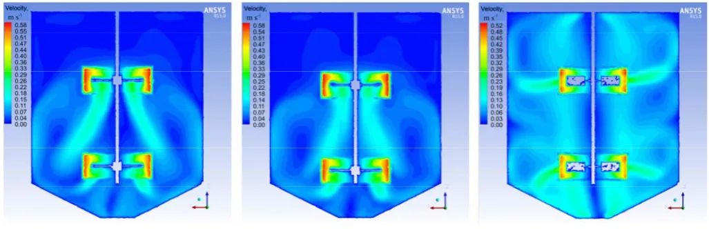
Figure 2 presents velocity contours within vertical
plane, demonstrating the sweeping ring from top to the
bottom of the reactor. According to the simulation results,
six-flat-blade disc turbine impeller is more appropriate
than the two other impellers.
a. Six-blade turbine impeller b. Four-blade turbine impeller c. Six-flat-blade disc turbine impeller
Figure 2 Velocity contours in the vertical plane of symmetry
As can be seen in the Figure 2, the rings on the lower
part of the impeller hit the bottom of the tank before
being diverted toward the walls around, with the outflow
from the impellers generating several vortexes along their
way backward. As was mentioned before, the impellers
drive the flow toward the surrounding walls and then a
major portion of the fluid ascend along the wall. Due to
the produced radial pressure gradient by tangential
movement, this flow returns toward central axis of the
tank and, finally, due to gravity, returns toward the stirrer
in the form of a depression.
The pitched-blade impeller with angled blades
generates both axial and radial flow in low- to medium-
viscosity fluids with a down-pumping flow. The impeller
produces slightly higher shear at its blade surface than a
hydrofoil impeller does, which gives a good balance
between pumping and shear action. So this is considered
to be a good general-purpose impeller.
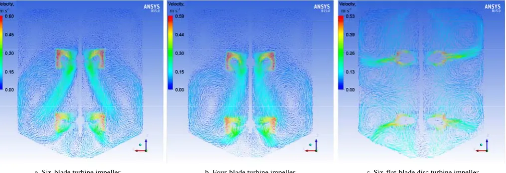
Vector variations in velocity field across the vertical
plane of symmetry for six-blade turbine impeller are
shown in Figure 3. The variations indicate that, a part of
the flow move upward while the other part goes down.
Further, the velocity vectors reveal chaotic nature of the
flow for lower velocities. With reference to the speed
contour, the magnitude of velocity is maximal at the
blade tips. An axial rotating ring can be observed
considering the direction of the outgoing vectors. In
Figure 3, the generated rotational rings around each
impeller are evident. The rings are generated above and
below each of the impellers. Velocity vectors across the
horizontal plane well confirm the rotational nature of the
flow which is, indeed, of a vortex form. The following
figure presents a close view of the velocity vectors across
the vertical plane of symmetry. Average flow is
determined by the circular movement established in
Figure 3, it can be seen that the fluid particle followed a
circular path in horizontal plane. Further, based on the
figures, one can understand that the circular movement is
smaller than the tangential movement at almost anywhere
within the fluid. Figure 4 represents the designed stirred
reactor for biogas production with six-blade turbine
impeller as selected stirrer.
a. Six-blade turbine impeller b. Four-blade turbine impeller c. Six-flat-blade disc turbine impeller
Figure 3 Changes of velocity square in stirred reactor for the speed of 30 rpm in the vertical plane of symmetry
Figure 4 The designed stirred reactor for biogas production, l: 3D drawing, r: photo
4 Conclusion
The main purpose of sludge mixing is to homogenize
the biogas reactor’s content and to avoid the sludge
deposits in the bottom area (Manea and Robesco, 2012).
In present study, the behavior of three types of impeller
inside the biogas reactor was simulated using the rotating
frame model and standard k-ε turbulence model utilizing
Fluent 15.0 Software. The simulation results indicated
that, the mixing operation was more appropriate for
six-blade turbine impeller and its reaction rate was
desirable at the center of the reactor where there was
region of high velocity. The success of the six-blade
turbine impeller was concluded by surveying the flow
pattern provided by CFD. This type of impeller provides
an axial flow which is desired for homogeneity of fluid.
Axial flow occurs when fluid is pushed up or down along
the axis or shaft of the impeller. On the other hand, this
impeller also provides the maximum mixing zone.
However, hosting regions of low velocity, the zones
farther from the stirrer suffered from lower mixing
operation performance and reaction rate. Determination
of the appropriate impeller is caused to lower power
consumption and shorter mixing time. The investigation
about the effect of the stirrer velocity, the type of
substrate and the direction of stirrer on flow pattern and
mixing performance can considered as the subjects for
future research.
References
Ahmed, S. U., P. Ranganathan, A. Pandey, and S. Sivaraman. 2010. Computational fluid dynamics modeling of gas dispersion in multi impeller bioreactor. Journal of Bioscience and Bioengineering, 109(6): 588–597.
Cumby, T. R. 1990. Slurry mixing with impellers: Part 1, theory and previous research. Journal of Agricultural Engineering Research, 45: 157–173.
Dehghani, M. A. 2008. Numerical simulation with Fluent 6.3 software. In Introduction to Computational Fluid Dynamics software and the ability of Fluent software, ch. 1, Tehran: Naghus Andisheh Press. (In Persian)
Ding, J., X. Wang, X. Zhou, N. Ren, and W. Guo. 2010. CFD optimization of continuous stirred-tank (CSTR) reactor for biohydrogen production. Bioresource Technology, 101(18): 7005–7013.
El-Mashad, H. M., W. K. P. Van Loon, G. Zeeman, and G. P. A. Bot. 2005. Rheological properties of dairy cattle manure. Bioresource Technology, 96(5): 531–535.
Kaparaju, P., I. Buendia, L. Ellegaard, and I. Angelidakia. 2008. Effects of mixing on methane production during thermophilic anaerobic digestion of manure: lab-scale and pilot scale studies. Bioresource Technology, 99 (11): 4919–4928.
Karim, K., K. T. Klasson, R. Hoffmann, S. R. Drescher, D. W. DePaoli, and M. H. Al-Dahhan. 2005. Anaerobic digestion of animal waste: effect of mixing. Bioresource Technology, 96(14): 1607–1612.
Kim, I. S., D. H. Kim, and S. H. Hyun. 2002. E ect of particle size and sodium concentration on anaerobic thermophilic food waste digestion. Water Science and Technology, 41(3): 67–73. Li, M., G. White, D. Wilkinson, and K. J. Roberts. 2004. LDA
measurements and CFD modeling of a stirred vessel with a retreat curve impeller. Industrial and Engineering Chemistry Research, 43(20): 6534–6547.
Manea, E., and D. Robescu. 2012. Simulation of mechanical mixing in anaerobic digesters. UPB Scientific Bulletin, Series D, 74 (2): 235–242.
McMahon, K. D., P. G. Stroot, R. I. Mackie, and L. Raskin. 2001. Anaerobic codigestion of municipal solid waste and biosolids under various mixing conditions-II: microbial population dynamics. Water Research, 35(7): 1817–1827.
Mirro, R., and K. Voll. 2009. Which impeller is right for your cell line? A guide to impeller selection for stirred-tank bioreactors. BioProcess International, 7(1): 52–58.
Nigam, K. D. P., and A. Schumpe. 1996. Three-phase sparged reactors, Gordon and Breach Science Publishers.
Rico, C., J. L. Rico, N. Muñoz, B. Gómez, and I. Tejero. 2011. Effect of mixing on biogas production during mesophilic anaerobic digestion of screened dairy manure in a pilot plant. Engineering in Life Sciences, 11(5): 476–481.
Shekhar, S. M., and S. Jayanti. 2002. CFD study of power and mixing time for paddle mixing in unbaffled vessels. Chemical Engineering Research and Design, 80(5): 482–498.
Shen, F., L. Tian, H. Yuan, Y. Pang, S. Chen, D. Zou, B. Zhu, Y. Liu, and X. Li. 2013. Improving the mixing performances of rice straw anaerobic digestion for higher biogas production by computational fluid dynamics (CFD) simulation. Applied Biochemistry and Biotechnology, 171(3): 626–642.
Shirmohammadpour, E., M. Rahimi, and M. R. Omidkhah. 2010. CFD investigation of mixing in containers equipped with three marine blade. In Proc. 2th National congress on new research in chemical engineering, Mahshahr Branch of Azad Islamic University, Mahshahr, Iran. (In Persian)
Stroot, P. G., K. D. McMahon, R. I. Mackie, and L. Raskin. 2001. Anaerobic codigestion of municipal solid waste and biosolids under various mixing conditions-I. Digester performance. Water Resources, 135(7): 1804–1816.
Vavilin, V. A., and I. Angelidaki. 2005. Anaerobic degradation of solid material: importance of initiation centers for methanogenesis, mixing intensity, and 2D distributed model. Biotechnology Bioengineering, 89(1): 113–122.
Vedrenne, F., F. Béline, P. Dabert, and N. Bernet. 2008. The effect of incubation conditions on the laboratory measurement of the methane producing capacity of livestock wastes. Bioresource Technology, 99 (1): 146–155.
Wu, B. 2010. Computational fluid dynamics investigation of turbulence models for non-newtonian fluid flow in anaerobic digesters. Environmental Science and Technology, 44(23): 8989–8995.
Yadvika, Santosh, T. R. Sreekrishnan, S. Kohli, and V. Rana. 2004. Enhancement of biogas production from solid substrates using different techniques-a review. Bioresource Technology, 95(1): 1–10.