Auto-steering based precise coordination method for in-field
multi-operation of farm machinery
Jie Wang
1,2,
Yuting Zhu
1,2,
Zhibo Chen
1,2,
Lili Yang
1,
Caicong Wu
1,2* (1. College of Information and Electrical Engineering, China Agricultural University, Beijing 100083, China;2. Key Laboratory of Remote Sensing for Agri-Hazards, Ministry of Agriculture and Rural Affairs, Beijing 100083, China)
Abstract: Multi-operation within a field and multi-machinery within a machinery operation are common in the scene of scaled
farm machinery service, especially with soaring usage of automated steering system in small and medium machinery cooperatives. The object of this study was to explore a precise and efficient in-field coordination method to realize flow-shop scheduling for farm machinery fleet equipped with RTK-GNSS based auto-steering system. The new method is based on three-dimensional coordinate system (XYZ), within which the concept of field, operation strip, and operation task were defined.
Under this concept framework, the operation strip state was further defined and its updating algorithm was designed, which can be used for optimization simulations and experiments. To evaluate the method, the waiting time between simulation and a real-world case was compared, and one cloud based prototype system was developed to demonstrate the practicability in the field by using NX200+ automated steering system. The simulations showed that the in-field coordination can shorten the waiting time between two adjacent operations. The waiting time between rotary hoeing and seeding can be shortened from 4 h to 6.3 min. The field experiment showed that the prototype system could keep good consistency of ridges for a fleet by sharing the guidance line.
Keywords: GNSS, auto-steering system, in-field coordination operation, farm machinery, method, simulation
DOI: 10.25165/j.ijabe.20181105.3827
Citation: Wang J, Zhu Y T, Chen Z B, Yang L L, Wu C C. Auto-steering based precise coordination method for in-field
multi-operation of farm machinery. Int J Agric & Biol Eng, 2018; 11(5): 174–181.
1 Introduction
RTK-GNSS based automated steering system can provide automatic guidance for single machinery unit with one-inch repeatability[1-7]. The auto-steering technology can improve operation quality and reduce dependence on skilled operator by automatically keeping the machine along the set path (guidance line). Automated steering systems are widely used in northeast- and northwest China nowadays. To realize flow-shop scheduling precisely[8-11] for machinery fleet with multiple operations and multiple machinery, it is necessary to share guidance lines within the machinery in real time. Since different farm machinery operations probably have different implement width or swath, the spacing of guidance lines may differ from each other. Therefore, both sharing mechanism of guidance lines and algorithm and management system for real time in-field coordination are needed to assist automated steering systems.
Seamless collaboration across spatial, temporal, operational, and machinery is an orientation especially toward fleet management of scaled farm and farm machinery service organization[12-15]. Sørensen and Bochtis[16] proposed that the total supply chain of large scale harvesting had four levels coordination,
Received date: 2017-09-26 Accepted date: 2018-01-15
Biographies: Jie Wang, Master candidate, research interest: LBS of farm machinery, Email: [email protected]; Yuting Zhu, Master candidate, research interest: LBS of farm machinery, Email: [email protected]; Zhibo Chen, Master candidate, research interest: LBS of farm machinery, Email: [email protected]; Lili Yang, Associate Professor, research interest: big data analysis, Email: [email protected].
*Corresponding author: Caicong Wu, PhD, Associate Professor, research interest: LBS of farm machinery. College of Information and Electrical Engineering, China Agricultural University, No. 17 Tsinghua East Road, Haidian District, Beijing, China. Email: [email protected].
i.e., in-field[17] logistics, inter-field[18] logistics, inter-sector logistics, and inter-regional logistics, and the individual efficiency of each machine unit depending on the performance of the system. Most of the researches focus on the inter-field coordination algorithm to improve machinery scheduling effectiveness[19-22]. Master-slave robot system and leader-follower system are the classical in-field coordination cases[23-27]. For the in-field level of farm operation, it can be subdivided into three lower levels, i.e., multi-operation, multi-machinery, and multi-factor. Multi-machinery coordination means that multiple machinery of the same operation cooperate together. For instance, five tractor-seeder units worked in one field simultaneously[28]. Multi-machinery concept replaces multi-operation concept in many references. For instance, to be more exact, tractor with a hayfork (as the master, leader, or primary) and dump truck (as the slave, follower, or customer) belong to two kinds of farm machinery operations, therefore, the coordination model of master-slave and leader-follower should be considered as multi-operation coordination. In further, multi-operation can also be subdivided into master-slave or parallel operation and sequential[29] or serial[17] operation.
strip and in-field coordination algorithm and mechanism for multi-operation and multi-machinery should be further studied.
Therefore, considering the application requirements of in-field collaborative operation in the high accuracy operation era, the paper proposed the concept of multi-operation strip, algorithm for operation strip state updating and waiting time calculation[17], mechanism for guidance lines (e.g., A-B line) sharing through the cloud and terminals of automated steering system, in order to improve the operation quality of multi-machinery operation and increase the transition efficiency of multi-operation of farm machinery.
2 Concept of sequential multi-operation
2.1 Case introduction
Figure 1 shows the flow-shop scenery of a machinery cooperative in Beijing, which owns more than 50 sets of tractors, harvesters, and implements. The left two machinery units in the figure were doing rotary hoeing, while the right two machinery units were doing plowing in the same field[28].
Figure 1 Case of sequential multi-operation system The overall arrangement of the agricultural machinery cooperative is shown in Table 1. Six agricultural machinery operations were arranged during the autumn tillage in 2014. The intersections between fertilizer spraying and disking harrow, plowing and rotary hoeing, and rotary hoeing and seeding contains coordinative actions. In further, except for fertilizer spraying, all other operation tasks have two or more sets of machinery unit. Imagine without the support of operation coordination, overlaps or skips were inevitable, which may cause both material and farmland waste.
Table 1 Multi-operation case of autumn tillage
No. Operation task Number Sep 26 Sep 27 Sep 28 Sep 29 Sep 30
Ⅰ Fertilizer spraying 1
Ⅱ Disking harrow 2
Ⅲ Plowing 3
Ⅳ Rotary hoeing 6
Ⅴ Seeding 5
Ⅵ Soil compacting 2
Table 2 lists the machinery units, operators, and durations of seeding operation. The table shows multi-machinery (five tractor-seeder units) with seeding task worked together in most of the seeding duration. However, the operators of seeding waited for some 4 h to enter the field on Sept 28, 2014, in which the rotary hoeing started at six in the morning.
Table 2 Multi-machinery operation of seeding task
Operation task Operator Start time End time
SeedingⅠ Wang X D 10:07 16:10
Seeding Ⅱ Wang K X 10:04 16:08
Seeding Ⅲ Peng J K 10:14 16:10
Seeding Ⅳ Gao N 10:02 15:38
Seeding Ⅴ Jiang L G 10:14 15:58
2.2 Architecture of multi-operation
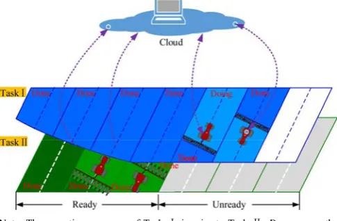
Abstracting from the above and related cases, the sketch map of sequential multi-operation and multi-machinery system can be expressed as Figure 2.
Note: The operation sequence of Task Ⅰ is prior to Task Ⅱ. Done means the strip has been finished, Doing means the strip is being done.
Figure 2 Cloud-terminal based architecture for in-field multi-operation and multi-machinery
2.2.1 System structure
The whole system mainly consists of the cloud, terminal, and wireless network. As Figure 2, a prototype system was developed for the cloud and the tablet terminal. Four NX200+ atuomated steering systems (Figure 4a), upgraded from NX200 of stand-alone version, were equipped on the John Deere 1204 tractors and used for the field experiments. Each terminal has a SIM card to use 4G wireless network.
Table 3 Functions of multi-operation prototype system
Component Main functions
Cloud
Field digital map manages Operation tasks manage
Operation strips divide and state update & exchange Terminal
(tablet)
Operation tasks download & manage Operation strips state update & upload Terminal
(NX200+)
Guidance lines upload & download Positions report
NX200 functions
CHC LT600 tablet (LT600T) and ZTE BLADE_V0820 (V8) were used for simulating. The two kinds of terminal connects to BeiDou Ground-based Augmentation System[35] to get the FindM service, which improved the accuracy of the terminal to 1 m. 2.2.2 System workflow
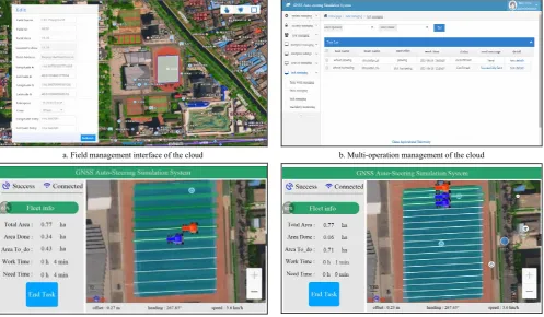
a. Field management interface of the cloud b. Multi-operation management of the cloud
c. Disking harrow simulation in the terminal d. Plowing simulation in the terminal Figure 3 Coordinative operation of multi-operation and multi-machinery
a. NX200+ b. LT600T ZTE V8
Figure 4 Terminals for experiments and simulations
2.3 Definition of multi-operation strip
Figure 2 just lists two adjacent operations for the field. The figure illastrates high accuracy of pass-to-pass by using atuomated steering system and the flow-shop working mode. In this case, field should be divided into strips according to machinery swath. The interrelation between two or more operations is quite important and is meanningful to shorten the transition time between adjacent operations.
Three-dimensional coordinate system, XYZ, is designed to
describe field, operation strip, and operation tasks. Lower-left field corner is pointed as the coordinate origin O. The X-axis is
perpendicular to the original A-B line and points to the right side of the field, and the Y-axis is perpendicular to the X-axis and
rotates 90 degrees counterclockwise. The Z-axis is determined
as a matter of fixed convention by the right-hand-thread rule. Both units of the X-axis and the Y-axis are distance (m), while the
Z-axis represents operation tasks considering the operation
sequence.
a. Single-operation b. Two-operation
2.3.1 Single-operation strip
An operation strip is a virtual lane-shaped area of the field divided for strip-following during farm machinery operation with centimeter level accuracy. The operating width of strip depends on the implement width or swath of the machinery. Figure 5a is the overhead view of operation strips expressed in XOY. For the
n-th operation task (N is total), the field can be divided into M(n)
strips, its operation strip can be expressed as following:
, 1,2,..., ( )
n i
strip i= M n
A-B line here, used for strip-following steering, is defined as the original guidance line cross through coordinate origin O. For
each operation strip, its guidance line is defined as A-Bni which is generated by offsetting the following spacing from the original guidance line:
_ n ( 0.5) n, 1, 2, ... , ( )
i
offset A B− = −i ×width i= M n 2.3.2 Multi-operation strip
As mentioned above, operation strip is a virtual and dynamic concept, since different operation task probably has different strip division. Figure 5b shows two-operation strip division. In the case, operation task I (operation1) is prior to operation task II
(operation2), and both operation tasks share the same original A-B line. Obviously, in production practice, operation1 should be
finished prior to operation2, therefore, the latter’s planning
dependents on the former’s progress.
2.3.3 Identification of operation strip
As Figure 6 shows, interval is defined to describe the operation strip in XOZ, in which the operation strips are abstracted to the line segments. The segment length is equal to the implement width or swath of machinery. Interval is described by two points corresponding to the endings of line segment. For instance, for the i-th operation strip of the n-th operation task, the interval can be
expressed as stripni ((i–1)×widthn, i×widthn).
Figure 6 Definition of interval for operation strip in XOZ
2.4 Algorithm of strip state updating
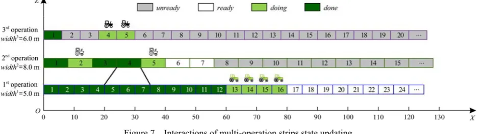
As Figure 7 shows, suppose three operations are being undertook. Some of the strips of the first operation should be finished and be ready for the second operation, but it is not necessary to complete all the strips. The third operation is also dependent on the progress of the second operation, and so on. The interactions are meaningful to improve the transition efficiency.
Figure 7 Interactions of multi-operation strips state updating 2.4.1 Strip state and its collection
Strip state means the completion situation of operation strip during farm operation. The first operation does not have unready
state, while all other operations have four kinds of state, i.e.,
unready, ready, doing and done, as Table 4 and Figure 7. Figure 8 shows the deterministic finite state automata. When the server gets the updating information of the operation strip, the algorithm will successively update the strip state of current operation according to the prior operation strip state.
StripReadyn and StripDonen are defined as the collections to
store the ready and done operation strips, respectively. Take the first operation as example, supposed StripDone1 is (0, 10) now,
when Strip1(10, 15) finished, the union (∪) of the two sets would be (0, 15), which is updated as following formulation:
StripDone1=StripDone1∪strip1(10,15)
Table 4 Definition of strip state
State Definition unready The specific strip is not ready for operating.
ready The specific strip is ready for operating. doing The specific strip is being occupied and operated.
done The specific strip has been finished.
Figure 8 Deterministic finite state automata 2.4.2 Strip state updating
For single-operation tasks, the judgement of operation access is simple. While for multi-operation tasks, it is much more complex, since the prior operation should prepare the workface for the subsequent operation. For instance, the strip24(24, 32) in Figure 7
depends on the state of the combination of strip15, strip16, and strip17, i.e., StripDone1(20, 35).
The state updating algorithm of multi-operation can be illustrated as following two steps:
strips. When machinery enters related strip, the strip’s state would change from ready to doing. When the machinery leaves
the strip, its state would become done finally, and StripDone1
collection would be updated.
(2) For the second operation, once any of the strip becomes
done of StripDone1, the StripReady collection and StripDone
collection of the subsequent operation would be updated in time also. Therefore, once any of the strips of the prior operation updated, the subsequent operation strip should be updated immediately by going through the previous operation strip collection.
In practice, the strip state could be pushed to the terminal of automated steering system to guide the operators to enter the ready
operation strip.
2.5 Algorithm of waiting time calculating
The waiting time (Twait) between two sequential operations affect the working efficiency. It is difficult for the farmer and the manager of the cooperative to determine the entry time accurately without enough working information of two adjacent operations. It is better for the operators of follow-up operation to enter the field as early as possible.
To simplify the question, suppose the operation path of the same operation would be traversed from one side to another side of the field. To calculate the waiting time, the finished area of the prior task is treated as a convex polygon, the problem of time overlap can be transformed to the problem of space overlap. The prior convex polygon and the follow-up convex polygon are defined as S1and S2respectively (Figure 9). The technical route of waiting time calculation is shown in Figure 10. Only when S2
is inscribed in S1at any time during whole duration of the prior operation, the result of waiting time is appropriate.
a. operating area (S1) b. S2 overlaps with S1 c. S2 inscribed in S1 Figure 9 Spatial relationships between two adjacent operations
Figure 10 Algorithm of waiting time calculating
3 Simulation
Two test schemes were designed to verify the algorithms. The first scheme was conducted in Matlab simulation program. The second scheme was conducted with the prototype system on the university campus.
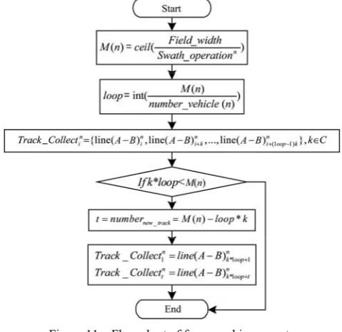
The simulation program was developed in Matlab technical programming language (The MathWorks, Inc., Natwick, Mass). Five operation tasks including fertilizer spraying, disking harrow, plowing, rotary hoeing, and seeding in Table 1, were selected for multi-operation and multi-machinery simulation. Suppose the machinery units would adopt alternative tillage working route and be realized as Figure 11. Strips were allocated equally to each machinery, and the working route of i-th machinery in n-th
operation was stored in the Track_Collectni.
Figure 11 Flow chart of farm machinery route
The simulation was entirely based on the case introduced in Figure 1. The parameters of selected operation tasks and farm machinery were acquired and calculated as following:
field_length_width = (414, 300 m)
swath_operation = (18, 2.5, 1.5, 2.5, 1.8 m)
number_vehicle = (1, 2, 3, 6, 5 pcs) velocity_vehicle = (10, 6, 6, 6, 6 km/h) U-turn_time_vehicle = (30, 30, 30, 30, 30 s)
One LT600T (Figure 4a) and one V8 (Figure 4b) were used for simulating the disking harrow operation. One LT600T, one V8, and one ordinary mobile phone were used for simulating the plowing operation. The LT600T and V8 connected to BeiDou Ground-based Augmentation System[35] to get the FindM service, which improved the accuracy of the terminal to 1 m. The second scheme was conducted with the prototype system on the playground of China Agricultural University in Beijing. The object was to validate the exchange capacity of the cloud and the guidance capacity of the terminal. The authors were assumed as the operators of machinery and were only guided by the prototype system.
4 Experiments
Group I shared guidance line by the cloud, while group II collected coordinates of guidance line manually. For group I, the coordinates of point A and point B were set in the field and uploaded to the server by tractor A with NX200+. Then, tractor B with NX200+ downloaded point A and point B. Each tractor went through the field by using auto-steering system. The operators would make U-turn manually at the headland. Here we set both of the implement swath to 5 m. Tractors would skip one strip when making U-turn.
For the comparative group, tractor A set point A and point B firstly, then tractor B was driven to the same place to set the coordinates of guidance line. The travelling mode was similar with the above one.
5 Results and discussion
5.1 Operation strip dividing
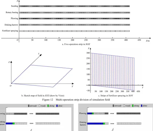
The field for simulation is the one of the case introduced in Figure 1, which located in the suburb of Beijing. Figure 12 shows
the result of operation strip division in XOZ, XYZ, and XOY.
Figure 12a shows the operation strips of five selected operations divided by the simulation program (Matlab). Figure 12b is the sketch map of the field in XYZ drew by Visio 2013. Figure 12c is the operation strip of fertilizer spraying task in XOY
and A-B line for each operation strip generated by Matlab program. From the figures, we can infer that the interval definition can well express the operation strip and the interrelation between adjacent operation tasks.
In production practice, Figure 12c would be showed in the terminals of automated steering system, and the strip states could be identified by specified colors. Relative coordinate system is used in the research, which may limit the extension.
5.2 Strip state updating
Figure 13 shows the instantaneous state of two types of operation strip during simulation in Matlab program. In the simulation program, the simulating velocity of vehicles is 128× speed, and the pictures were refreshed every 0.1 s.
a. Five-operation strip in XOZ
b. Sketch map of field in XYZ (drew by Visio) c. Strips of fertilizer spraying in XOY Figure 12 Multi-operation strip division of simulation field
a. At seventeenth minutes b. At thirty-third minutes
Figure 13 Simulation results of two-operation In the program, plowing operation simulation started 20 min
later than disking harrow operation simulation. In the first 20 min,
would be updated. Figure 13b shows the ready (white background)
operation strip of plowing can be selected for tillage immediately.
5.3 Waiting time calculating
Table 5 is the result of waiting time calculation.
Table 5 Comparison of waiting time
Transmit between operations In practice In simulation Fertilizer spraying → Disking harrow 21 min 3.8 min
Disking harrow → Plowing 8 h* 3.8 min
Plowing →Rotary hoeing 3.6 h 3.5 h Rotary hoeing →Seeding 4 h 6.3 min Note: * Disking harrow was finished at 14:55 on sept 26, 2014. Plowing was arranged at 10:00 on the next day.
From the above table, plowing and seeding were arranged 8 h and 4 h after the ending of the prior operation in practice. By using the multi-operation algorithm, the minimum of waiting time are 3.8 min and 6.3 min respectively, which means flow-shop planning could be more compact. Rotary hoeing was arranged appropriately through the experience of the staff.
Obviously, the algorithm could improve the overall efficiency of farm machinery management by shortening the waiting time between two adjacent operations.
5.4 Coordination between two operations
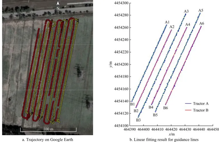
Figures 3c and 3d show the monitoring interface of the terminal during simulation on the playground. Disking harrow simulation started 3 min earlier than plowing simulation. The simulation showed that the prototype system could guide two operations orderly. Figure 14 shows the trajectory collected by NX200+ in the field, which verified that the system could guide
two machinery orderly. The swaths of the selected operation in the prototype system had been enlarged four times compared to the original swath, in order to reduce the affection of tablet and smartphones with low accuracy (sub meter level). Besides the positioning accuracy, the prototype system just realizes the basic functions of multi-operation coordinative operation, and is far from the requirements of real practice. For the further development, the prototype system can be integrated into the software of GNSS based automated guidance system.
5.5 Accuracy of guidance lines
Figure 14 shows the trajectory and linear fitting result of guidance lines of group I. We studied the slopes of the fitting lines. The mean, standard deviation (SD), and coefficient of variation (CV) of six fitting lines in group I is 4.91 rad, 0.01 rad, and 0.26%, respectively. While the mean, SD, and CV of group II is 4.78 rad, 0.04 rad, and 0.74%, respectively. Therefore, we can conclude that group I has higher accuracy than group II, which means that the multi-operation coordinative system could keep good consistency of ridges for a fleet by sharing the guidance line.
In fact, there should be no errors in theory when we shared the guidance line through the cloud, since all the terminals use the same coordinates of point A and point B. The CV of slope in group I reflects the errors of machinery controlling by using auto-steering system.
Over the farmland, there are two groups of high voltage wires. From the left to the right, the positioning accuracy of the first six guidance lines is RTK level, while others were not so good because of interrupting of differential signal. Therefore, we selected the first six sets of data for statistics.
a. Trajectory on Google Earth b. Linear fitting result for guidance lines Figure 14 Trajectory and linear fitting result of guidance lines of group I
6 Conclusions
This research proposed the cloud-terminal based sketch map of coordination operation for multi-operation and multi-machinery to realize flow-shop working. The definition of field coordinate system, operation strip, and interval for strip identification were first given. Within this framework, algorithms of strip state updating for multi-operation and waiting time calculating between
accurately compute the waiting time and to effectively compact the farm machinery operation. The prototype system could also keep good consistency of ridges for a fleet by sharing the guidance line.
Acknowledgements
Thanks for the support of National Key Research and Development Program of China (No. 2016YFB0501805), Chinese Universities Scientific Fund (No. 2017QC140). Thanks for Shanghai HuaCe Navigation Technology Ltd. who provided GNSS RTK based tablet for experiments.
[References]
[1] Rovira-Más F, Chatterjee I, Sáiz-Rubio V. The role of GNSS in the navigation strategies of cost-effective agricultural robots. Computers and Electronics in Agriculture, 2015; 112: 172–183.
[2] Bechar A, Vigneault C. Agricultural robots for field operations. Part 2: Operations and systems. Biosystems Engineering, 2017; 153: 110–128. [3] Carballido J, Perez-Ruiz M, Emmi L, Aguera J. Comparison of
positional accuracy between rtk and RTX GNSS based on the autonomous agricultural vehicles under field conditions. Applied Engineering in Agriculture, 2014; 30(3): 361–366.
[4] Ming L, Imou K, Wakabayashi K, Yokoyama S. Review of research on agricultural vehicle autonomous guidance. Int J Agric & Biol Eng, 2009; 2(3): 1–16.
[5] Han X, Kim H-J, Jeon C W, Moon H C, Kim J H. Development of a low-cost GPS/INS integrated system for tractor automatic navigation. Int J Agric & Biol Eng, 2017; 10(2): 123–131.
[6] Hu J, Gao L, Bai X, Li T, Liu X. Review of research on automatic guidance of agricultural vehicles. Transactions of the CSAE, 2015; 31(10): 1–10. (in Chinese)
[7] Ji C, Zhou J. Current situation of navigation technologies for agricultural machinery. Transactions of the CSAM, 2014; 45(9): 44–54. (in Chinese) [8] [8] Bochtis D D, Sørensen C G C, Busato P. Advances in agricultural
machinery management: A review. Biosystems Engineering, 2014; 126: 69–81.
[9] Conesa-Munoz J, Gonzalez-De-Soto M, Gonzalez-De-Santos P, Ribeiro A. Distributed multi-level supervision to effectively monitor the operations of a fleet of autonomous vehicles in agricultural tasks. Sensors, 2015; 15(3): 5402–5428.
[10] Senlin G, Nakamura M, Shikanai T, Okazaki T. Hybrid petri nets modeling for farm work flow. Computers and Electronics in Agriculture, 2008; 62(2): 149–158.
[11] Bochtis D D, Dogoulis P, Busato P, Sørensen C G, Berruto R, Gemtos T. A flow-shop problem formulation of biomass handling operations scheduling. Computers and Electronics in Agriculture, 2013; 91: 49–56. [12] Wu C. Time-windows based temporal and spatial scheduling model for
agricultural machinery resources. Transactions of the CSAM, 2013; 44(5): 237–241, 231. (in Chinese)
[13] Valentinov V. Why are cooperatives important in agriculture? An organizational economics perspective. Journal of Institutional Economics, 2007; 3(1): 55.
[14] Balta H, Bedkowski J, Govindaraj S, Majek K, Musialik P, Serrano D, et al. Integrated data management for a fleet of search-and-rescue robots. Journal of Field Robotics, 2017; 34(3): 539–582.
[15] Fountas S, Carli G, Sørensen C G, Tsiropoulos Z, Cavalaris C, Vatsanidou A, et al. Farm management information systems: Current situation and future perspectives. Computers and Electronics in Agriculture, 2015; 115: 40–50.
[16] Sørensen C G, Bochtis D D. Conceptual model of fleet management in agriculture. Biosystems Engineering, 2010; 105(1): 41–50.
[17] Bochtis D D, Sørensen C G, Vougioukas S G. Path planning for in-field navigation-aiding of service units. Computers and Electronics in Agriculture, 2010; 74(1): 80–90.
[18] Gutman P O, Ioslovich I. Inter-field routes scheduling and rescheduling for an autonomous tractor fleet at the farm. International Conference on Methods and MODELS in Automation and Robotics, IEEE, 2013; pp.812–817.
[19] Bochtis D D, Sørensen C G. The vehicle routing problem in field logistics part I. Biosystems Engineering, 2009; 104(4): 447–457. [20] Bochtis D D, Sørensen C G. The vehicle routing problem in field
logistics: Part II. Biosystems Engineering, 2010; 105(2): 180–188. [21] Bochtis D D, Vougioukas S G. Minimising the non-working distance
travelled by machines operating in a headland field pattern. Biosystems Engineering, 2008; 101(1): 1–12.
[22] Bochtis D, Vougioukas S, Griepentrog H W. A mission planner for an autonomous tractor. Transactions of the ASABE, 2009; 52(5): 1429–1440.
[23] Noguchi N, Will J, Reid J, Zhang Q. Development of a master–slave robot system for farm operations. Computers and Electronics in Agriculture, 2004; 44(1): 1–19.
[24] Noguchi N, Will J, Ishii K, Reid J. Development of master-slave robot system-obstacle avoidance algorithm. Proceedings of the Conference on Automation Technology for Off-Road Equipment, ASABE, 2002. doi: 10.13031/2013.10065.
[25] Zhang C, Noguchi N, Yang L. Leader–follower system using two robot tractors to improve work efficiency. Computers and Electronics in Agriculture, 2016; 121: 269–281.
[26] Zhang L, Ahamed T, Zhang Y, Gao P, Takigawa T. Vision-based leader vehicle trajectory tracking for multiple agricultural vehicles. Sensors, 2016; 16(4):578. doi: 10.3390/s16040578
[27] Auat Cheein F A, Scaglia G, Torres-Torriti M, Guivant J, Javier Prado A, Arno J, et al. Algebraic path tracking to aid the manual harvesting of olives using an automated service unit. Biosystems Engineering, 2016; 142: 117–132.
[28] Wu C C, Zhou L, Wang J, Cai Y P. Smartphone based precise monitoring method for farm operation. Int J Agric & Biol Eng, 2016; 9(3): 111–121.
[29] Orfanou A, Busato P, Bochtis D D, Edwards G, Pavlou D, Sorensen C G, et al. Scheduling for machinery fleets in biomass multiple-field operations. Computers and Electronics in Agriculture, 2013; 94: 12–19. [30] Han X Z, Kim H J, Kim J Y, Yi S Y, Moon H C, Kim J H, et al.
Path-tracking simulation and field tests for an auto-guidance tillage tractor for a paddy field. Computers and Electronics in Agriculture, 2015; 112: 161–171.
[31] Zhou K, Leck Jensen A, Sorensen C G, Busato P, Bothtis D D. Agricultural operations planning in fields with multiple obstacle areas. Computers and Electronics in Agriculture, 2014; 109: 12–22.
[32] Jensen M A F, Bochtis D, Sørensen C G, Blas M R, Lykkegaard K L. In-field and inter-field path planning for agricultural transport units. Computers and Industrial Engineering, 2012; 63(4): 1054–1061.
[33] Han X Z, Kim H-J, Moon H-C, Kang Y-S, Kim J-H, Kim Y-J. Development of path generation algorithms for Korean auto-guidance tillage tractor. ASABE Annual International Meeting, Dallas, Texas, July 29 - August 1, 2012; pp.4723–4732.
[34] Hu J, Li T. Cascaded navigation control for agricultural vehicles tracking straight paths. Int J Agric & Biol Eng, 2014; 7(1): 36–44.