A New IPTV Multicast Fast Reroute Method
https://doi.org/10.3991/ijoe.v14i04.8379Wang Yan(!), Cai Jifei, Zhang MingMing, Cheng MingZhi
Beijing Institute of Graphic Communication, Beijing, China [email protected]
Abstract—This document proposes an IP multicast fast convergence me-thod based on differentiating primary and backup PIM(Protocol Independent Multicast) join. The multicast stream is only sent along one of the multicast primary and backup path, which enables the efficient multicast delivery under both normal and abnormal conditions. The Single stream FRR(Fast Re-Route) solution has the advantages of implementing fast multicast protection and of avoiding double multicast bandwidth occupation in both normal and abnormal situations.
Keywords—Path protection , IP multicast, Data communication
1
Introduction
Fast re-route (Fast Re-Route, referred to as FRR) is a network error tolerance poli-cy. The fast re-route may protect a link or a node, and may quickly perform switch-over when a fault occurs in the link or the node, so as to reduce a packet loss to the largest extent. IP FRR of unicast is that an IP routing protocol generates a preferred route (a primary route) and a corresponding backup route, so that when a fault occurs in an active path, IP traffic may be switched to a standby path for forwarding. Proto-col independent multicast (ProtoProto-col Independent Multicast, referred to as PIM) FRR of multicast is that the IP FRR of unicast or a statically configured standby path is used, and the active path and the standby path simultaneously forward multicast traf-fic, so that when a fault occurs in the active path, the multicast traffic may be switched to the standby path for forwarding, as stated in [1].
In a procedure of implementing the present invention, the inventors find that at least the following problem exists in the prior art: because the active path and the standby path simultaneously forward the multicast traffic, network bandwidth is wasted.
Because either primary or backup nodes forward multicast data packets, they should be able to identify on which path they are located and to take appropriate for-warding action according to this information. One feasible solution is to include a new join attribute in a PIM backup join message. During the transmission of the joins hop-by-hop on the backup path, the node(s) of backup path are disabled for data for-warding when creating the multicast forfor-warding entries. If the failure is detected on the primary path, the backup path is notified and the forwarding entry on backup path node which was previously disabled is enabled for data forwarding.
The Single stream FRR solution has the advantages of implementing fast multicast protection and of avoiding double multicast bandwidth occupation in both normal and abnormal situations.
2
Principle of Single Stream Solution
Fig. 2. Schematic flow chart of a method for forwarding multicast traffic
As shown in Fig. 2, the method for forwarding multicast traffic in this embodiment may include:
201 to 206: The RTD receives a third multicast join message, sends a first multi-cast join message and a first multimulti-cast join message' directly to the RTA.
For example, the first multicast join message may be an ordinary PIM join packet, and an active path may be established according to a process in the prior art, and the active path may be used to forward multicast traffic, which is not repeatedly described here. For another example, the first multicast join message may carry a newly added join attribute, such as active path information. For example, differences between the first multicast join message' and the first multicast join message include that addres-ses of upstream neighbors routing devices are different and source addresaddres-ses are diffe-rent.
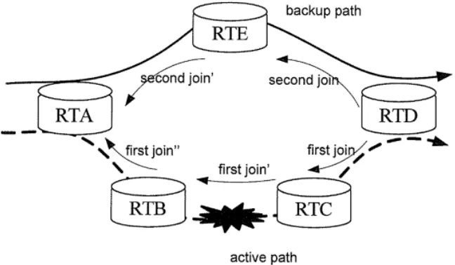
Fig. 1.Fig. 3.Schematic structural diagram of a network topology
Fig. 3. Schematic structural diagram of a network topology
path fault, opens a backup outbound interface toward the RTB, and meanwhile, finds that the primary inbound interface identifier in the fault information is a primary in-bound interface on a path from the RTC to a multicast source. The RTC is set to that it may forward the traffic toward a backup inbound interface of the RTD. The RTD receives the fault information, opens a backup outbound interface corresponding to the fault information, and forwards the traffic through the backup outbound interface. The RTE receives the fault information, and does not perform path switchover becau-se it does not receive backup joining that includes active path information of the RTB and the RTC. Finally, the multicast traffic is forwarded by the RTD to the RTC, and is then forwarded to the RTB.
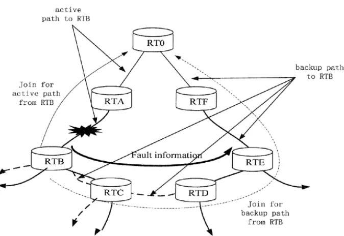
Fig. 4. Schematic simplified structural diagram of a network topology
router of the RTB on the active path, is a root node of the active path and the standby path. For example, the root node may be a merge point of an active/standby tree, or is a router directly connected to a source, or is designated by a user.
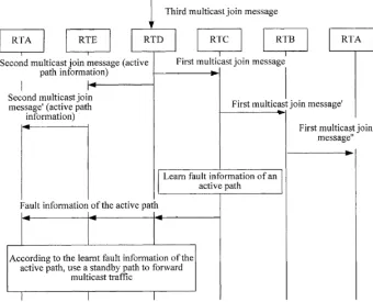
Fig. 5. Schematic flow chart of a method for forwarding multicast traffic
Fig. 5 is a schematic flow chart of a method for forwarding multicast traffic ac-cording to yet another embodiment of the present invention. As shown in FIG. 4B, the method for forwarding multicast traffic in this embodiment may include:
401 to 403: The RID and the RTE receive a third multicast join message, send a first multicast join message and a first multicast join message' to the RTA.
proce-dure of establishing the path is not repeatedly described here. The active path estab-lished here is an active tree.
404: The RTD and the RTE send a second multicast join message to the RTC. For example, the second multicast join message may carry the active path informa-tion, for example, a tree identifier (ID).
2.1 Primary and Backup Path Setup
The backup multicast path is set up using backup PIM join. The join is sent by the initiating node of the backup path from the backup IP FRR upstream interface or from a statically configured backup interface towards the multicast source. The join is transmitted hop-by-hop upwards and is terminated when reaching the root of the mul-ticast tree (i.e. Source DR or RP, as stated in [2]), or when merging with primary forwarding states created by primary join. On the merging point, only the primary states are maintained.
The forwarding state(s) on backup path are disabled by default for data forwarding when being created by the backup joins, which requires the backup join to be flagged to be differentiated from the primary ones. A new join attribute [RFC5384] (referred to as e.g. Multicast FRR join Attribute, or MFA), is suggested to be introduced to serve this purpose and a new hello option for this attribute should be defined to nego-tiate this capability. The format of the attribute and its hello option are respectively defined in section 3.1 and 3.2
To make precise switching from a primary path to a backup path for multiple load-balancing primary paths, an additional identification for the primary path should be included in the MFA attribute of a backup join. The primary path ID could be the interface ID of a router ID, or a logic number configured for the primary path. In some cases multiple primary path IDs have to be included in the backup join and they have to be merged when backup join has to be sent upwards. PIM incremental me-chanism [PORT] could be used in these cases to reduce information to be carried in the backup joins.
The establishing of primary path could be a normal PIM join process.In this case an ordinary PIM join is generated on the initiating node of primary path and is sent hop-by-hop upstream until the join arrives at the root of the tree or at the other valid forwarding branch.
2.2 Fault Processing
The fault on the primary path could be detected by using some fault detection me-chanism (e.g. BFD protocol), which is configured to be run between each pair of PIM neighbors, as stated in [3]. If error condition occurs, the node on the upstream or downstream of the error point will possibly detect it and should pass this error condi-tion to the backup path, and enable multicast data forwarding on it.
and forwarding of the packets should be rate-limited. The fault notification like this can be implemented by extending BFD or other protocol, which is not covered by this document.
When backup node(s) receive the notification packets, they will enable the multi-cast forwarding which was previous disabled. To select correct data stream switching to the backup path, the information of primary path ID should be carried in the notifi-cation. And prior to that, the backup path should record the primary path ID for cor-responding multicast forwarding entries during backup join operation.
After the enabling of the backup path, the multicast data will be forwarded along the path downstream to the initiating node of the backup path. The backup path initia-ting point then changes the backup incoming interface (IIF) as its RPF interface if no data is available from the primary IIF.
If primary path heals, multicast forwarding could choose to switch back to the pri-mary path. The pripri-mary join will be generated hop-by-hop to set up the pripri-mary path, as illustrated in section 2.1. Once the data is received from the primary IIF, the initia-ting node will change its RPF interface to its primary IIF. The node may also send a PIM prune message to tear down the backup path, and may possibly after waiting for a specified period of time, re-setup the backup path without stream using the same process as described in section 2.1.
The second multicast join message including the active path information may be implemented by newly defining a join attribute in a PIM join packet defined by RFC5384, as stated in [4]. The join attribute may be included in a source address in the PIM join packet.
In Fig. 6, a flag bit F, a flag bit E, an attribute type (Attr_Type), and length (Length) are all defined by using a protocol standard, which are not repeatedly descri-bed here. The Attr_Type identifies that the attribute is backup joining. A flag bit Flags is content of the attribute. For example, only one bit may be used, and 1 is used to represent PIM backup joining. Path Count identifies the number of Path IDs. The Path ID identifies the active path information, and is generally an identifier (for example, an IP address) of a multicast entry primary inbound interface of a router correspon-ding to the active path protected by the standby path.
3
The Definition of packet format
3.1 Multicast FRR join Attribute
Fig. 6. Format of the join attribute in the PIM join packet
! F-bit, Transitive Attribute. If this bit is set, the attribute is a transitive attribute; otherwise, it is a non-transitive attribute [RFC5384].
! E-bit, End of Attributes. If this bit is set, then this is the last Join Attribute appea-ring in the Encoded-Source Address field specified by [RFC5384].
! Attr_Type, Type of the Attribute. It should be set to a new value (e.g.) for this MFA join attribute, e.g., taking value of 8.
! Length, a 1-octet field specifying the length in octets, encoded as an unsigned binary integer, of the value field.
! Flags, flag for primary or backup join. 0 is for a primary join, 1 for backup join.
! Path Count, the number of path included following Path ID.
! Path ID, the Identification for this path.
3.2 PIM multicast FRR Hello Options
This multicast FRR Hello options are used for the PIM neighbors to negotiate the capability of multicast FRR join attribute. It has the format prescribed in [RFC5384] and the OptionType is defined a new value representing this MFA attribute in Fig. 7 .
! OptionType = 38
! OptionLength = 8
! OptionValue, reserved for future use
4
Scenario Analysis for Single Stream Forwarding
4.1 Disabling all nodes on backup path
In this method, when backup join is transmitted to set up the backup path, the ba-ckup forwarding states of all the nodes are by default disabled for multicast data for-warding when being created. When backup join arrives at a primary node that has primary forwarding state, it is ''absorbed'' and will not created any backup state there.
Because each backup path will be merged at transit or root node of a multicast tree, and each node on this backup path could be disabled or enabled for data forwarding, it is possible to implement relatively precise control of path switching.
Fig. 8. Example of an arbitrary tree topology
Figure 8 is an example of an arbitrary tree topology. Supposing RT6 has a downstream receiver and it is the initiating node of both the primary and backup path for this receiver. Then RT1-RT2-RT3-RT6 is setup as the primary path by primary join, and RT2-RT4-RT6 as the backup path by backup join. The backup forwarding states for the backup path, i.e. the outgoing interfaces of RT2 (the one towards RT4) and RT4 (towards RT6) are all disabled for multicast forwarding. Only primary path imports multicast stream through RT2 to RT6 and to the receiver.
If link between RT3 and RT6 goes down, the failure will be detected and be no-tified to RT2 and RT4 on backup path. They will be enabled the data forwarding on their outgoing interface, and the data will be imported from RT2, through RT4, to RT6 and the receiver.
has downstream multicast receiver. If any upstream failure on the primary path oc-curs, the node will turn to receive reverse stream from the backup path.
4.2 Disabling only root node on backup path
In this method, when backup join is sent hop-by-hop to setup the backup path, only the root node is disabled of its multicast data forwarding. The forwarding states on other nodes on the backup path are kept normal. In normal condition, the only stream comes from the primary path established by the primary join. If error occurs on the primary path, the root node of the backup path is notified of the failure, it then enables its data forwarding and the data stream will be delivered from the backup path to the receiver.
The primary join and backup join in this method can be used to setup primary and backup trees. In normal condition, only primary tree makes the multicast forwarding. When failure occurs on the primary tree, the root node of the backup tree could be notified to open its data forwarding and the multicast data will delivered over the backup tree to the receiver.
5
Summary
Embodiments of the present invention provide a method and an apparatus for for-warding multicast traffic, which are used to solve a problem in the prior art that net-work bandwidth is wasted because an active path and a standby path simultaneously forward multicast traffic, so as to save the network bandwidth.
It may be known from the foregoing technical solutions that, according to the em-bodiments of the present invention, the standby path that does not forward the multi-cast traffic is established beforehand, so that when a fault occurs in the active path, the standby path established beforehand can be used to forward the multicast traffic. Because the standby path does not forward the multicast traffic when the active path normally forwards the multicast traffic, double network bandwidth is not occupied, thereby saving the network bandwidth.
6
Acknowledgment
Funded projects No: 1. (06170115003/013) 2. (04190117029/001) 3. (TJSHG201510015011) 4. (KM20140015008)
7
References
[1]Qiao Xi. IP multicast. People's post and Telecommunications Press. March ,2017. Beijing China. P111-115
[3]Cui jianqun. Topology aware application layer multicast model construction and perfor-mance optimization method . Huazhong Normal University press .Jun,2013. Hubei China. P125-129
[4] Yan yan. Design and application of multicast routing protocol. People's post and Telecommunications Press. Sep ,2011. Beijing China. P73-76
8
Authors
Wang yan is an associate professor and a graduate tutor of automation at Beijing
Institute of Graphic Communication in China.
Cai Jifei, Zhang MingMing, and Cheng MingZhi are with Beijing Institute of
Graphic Communication, Beijing, China.