Please cite this article as: M. Pirzadeh, A. R. Toloei, A. R. Vali, Effects of Flight Dynamics on Performance of One Axis Gimbal System, Considering Disturbance Torques, International Journal of Engineering (IJE), TRANSACTIONS B: Applications Vol. 28, No. 8, (August 2015) 1108-1116
International Journal of Engineering
J o u r n a l H o m e p a g e : w w w . i j e . i r
Effects of Flight Dynamics on Performance of One Axis Gimbal System,
Considering
Disturbance Torques
M. Pirzadeh a, A. R. Toloei* b, A. R. Vali c
a Department of Electrical Engineering, Damavand Branch, Islamic Azad University, Damavand, Iran b Department of Aerospace, Shahid Beheshti University, Tehran, Iran
c Department of Electrical Engineering, Malek-Ashtar University of Technology (MUT), Tehran, Iran
P A P E R I N F O
Paper history:
Received 06 June 2015
Received in revised form 28 July 2015 Accepted 30 July2015
Keywords:
Gimbal Seeker Rate Gyro Servo-Tracking Loop LOS Rate
Flight Path
A B S T R A C T
The gimbal stabilization mechanism is applied to provide the stability of an object which is mounted on the gimbal by isolating it from the base angular motion and vibration. In this paper the model of one axis gimbal system with dynamic flying object is introduced. The gimbal torque relationships are obtained using Newton’s second law equation with the assumption that gimbal is rigid body. The system is modelled using SIMULINK MATLAB. In fact, the purpose of this research was to analyse the effects of flight dynamics on performance of one axis gimbal system. The simulation results are discussed and compared to show the validity of the gimbal system proposed at the flight path. Also, the results show that the gimbal system stabilizes the line of sight even when the disturbance torques affect the system performance.
doi: 10.5829/idosi.ije.2015.28.08b.01
1. INTRODUCTION1
Today, guided missiles which are aerodynamically unstable or non-linear in all or part of the flight path need control system for stability. Missile test flights are very expensive. Also, it is not reusable after a test launch. Seeker-based systems need detailed seeker modelling before mounting on the 3-axis motion simulator for final Hardware-In-Loop Simulation (HILS). The seeker system is tested independently for stabilization and tracking loop under trajectory dynamic conditions without the guidance loop; there is no sufficient insight for upgrading seeker design and just this helped to validate the simulator software. Thus, 6-DOF model with seeker and other subsystems have been validated as a priority. The simulations are based on mathematical models of missiles, target and environmental conditions, which can provide valuable information about the performance of the missile subsystem [1]. Inertial stabilized platforms (ISP) usually consist of an assembly of structure, bearings, and
1*Corresponding Author’s Email: [email protected] (A. R. Toloei)
performance are discussed [7]. To investigate and analyze the performance of gyro stabilized seeker, which must strictly isolate the LOS from the disturbance and vibration of missile. The model of one axis stabilization and tracking loop are constructed [8]. Two degree of freedom gimbal system has been introduced and its torque relationships are obtained in a simplified form supposing each gimbal is balanced [9]. For one degree of freedom gimbal studied in the literature [10], the static and dynamic imbalance disturbance torques created by the vibrations of operating environment can be eliminated by statically and dynamically balancing the gimbal, which is regarded costly and time consuming. A new finite-horizon tracking technique for nonlinear systems is offered. This technique is based on change of variables that converts the differential Riccati equation to a linear Lyapunov equation. To evaluate the structure of the 6DOF model in conjunction with the calculation of the desired seeker angles via numerical implementation is reported by Khamis et al. [11]. In the literature [12], 2-DOF internal model controller is used to attenuate the platform disturbance that couples to the gimbal inner axis (elevation axis) at angular rate of the seeker. The performance of model with constant LOS rate values and disturbances was investigated. The laser seeker is modeled experimentally, based on data obtained by conducting a series of tests. Also, the effects of torque disturbance are not considered [13, 14].
In this paper, a general simulation for estimating the total uncertainty in gimbal system is developed. To do so, one axis gimbal system with dynamic flying object and equations of motion is introduced. Then, the stabilization system is constructed so that several disturbance torques are included. Afterward, guidance law is introduced. The system is modeled using SIMULINK/MATLAB. Finally, seeker with missile dynamics, guidance and control loop, is tested for disturbance torque and angular velocities which are online imposed missile frame to seeker.
2. PROBLEM FORMULATION
2. 1. Missile Equations of Motion The airframe dynamics are calculated using the equations of motion for a rigid body. The translational motion of a body is defined in terms of the acceleration of the body’s center of mass that is measured from an inertial reference;
G
F ma
(1)where
F is the sum of external forces acting on the body. If the moving frame is attached to the center of mass of the body the scalar equations are [15]:( ) ( )
( )
( )
X
Y
Z
X Thrust g m u qw rv Y g m v ru pw
Z g m w qu pv
(2)
where (gX, gY, gZ)are components of gravitational
force vector expressed in the body coordinate system [15]. The components of the angular momentum are computed about the axes of a frame attached to the center of mass and move with the body. So, rotational equations are [15]:
( )
( )
( )
X X Y Z X
Y Y Z X Y
Z Z X Y Z
p M I qr I I I q M I rp I I I r M I pq I I I
(3)
At the end, Equation (4) is the Euler angles:
cos sin
sin
( cos sin ) cos
q r
p
r q
(4)
where( , , ) are the missile changes its orientation in space and the Euler angles change [15].
2. 2. Airframe The airframe can have any configuration, and this is expressed in the aerodynamic data that is used to calculate the aerodynamic forces and moments, and the moments of inertia and products of inertia in the equations of rotational motion. The aerodynamic force acting on the airframe has components (X Y, , Z) parallel to the body axes. These are determined by [15]:
0 0 0 X ref X Y ref Y
Z ref Z F q S C F q S C F q S C
(5)
where 2
0 0.5
q V is the dynamic pressure, andSref is a reference area, is the density of the atmosphere and V is the magnitude of the wind-corrected velocity or airspeed. The total aerodynamic moment is computed in the body coordinate system and is given by [15]:
0
0
0
X l ref refy
Y m ref refx
Z n ref refy
M C q S I
M C q S I
M C q S I
(6)
where Iref is the reference length of body. The functional form for the linearized aerodynamic force coefficients in the body coordinate system is given by [15]:
0
( 2 )
( 2 )
r r
q e
X X
Y Y Y r Y refy
Z Z Y e Z refx
C C
C C C C r I V
C C C C q I V
where and are the angle of attack and sideslip angle, respectively; ( , , )p q r are the components of the angular velocity vector about the body ( , , )x y z axes. Note that for the assumed symmetric missile,
Z Y
C C
, CZq CYr and Irefx Irefy . The
aerodynamic moment coefficients can be linearized just as the aerodynamic force coefficients were to yield [15]:
( 2 )
( 2 )
( 2 )
p a
q e
r r
l l a l refy l
m m m e m refx
n n n r n refx
C C C p I V C
C C C C q I V
C C C C r I V
(8)
where ( a, e, r) are angle of effective
control-surface deflection.
3. ONE AXIS GIMBAL SYSTEM
The seeker system contains two loops: track loop which is designed to maintain the measured bore sight error near zero, and stabilization loop that isolates the sensor from the flying object body motion and disturbances that would otherwise perturb the aim-point [6, 8]. The stabilization loop or so called servomechanism system is included in the track loop as shown in Figure 1.
Newton’s second law establishes that if a net torque
T is applied to a homogenous rigid mass having a moment of inertia J, then the body develops an angular acceleration α [1, 4, 6, 7] according to:
.
T J (9)
Therefore, in principle, all that is required to prevent an object from rotating with respect to inertial space is to ensure that the applied torque is zero. Also, a means for controlling the object so that it can be rotated in response to command inputs is usually required. Therefore, rate or displacement gyros are typically attached to the object to measure the inertial rotation about the axes that require stabilization and control. The gyro is used in a closed-loop servo system to counteract the disturbances and, at the same time, allow the object to be controlled from external command inputs [1, 4, 6, 7]. The single-axis stabilized gimbal is shown in Figure 2. The block diagram in Figure 3 shows the gimbal control system. It is typically configured as a rate servo. That is, the control system attempts to null the difference between the rate command input and the angular rate of the gimbal. Figure 3 shows the block diagram of the inertial stabilized platform control system [4, 6, 7]. From this figure, it can be seen that [4, 6, 7]:
1
Ae
Ae Ae
T J s J J
T J s
(10)
Kinematic Integration DC Motor
_
Rate Gyro
1/s
Torque Disturbances
Inertia Angle
Channel Receiver _
Tracking Loop
Stabilizing Loop
Compensator
Proportional compensator (track const)
Figure 1. One axis seeker [8]
(Body A)
(platform)
r
d
e i
j
k
Ae
Figure 2. A single-axis gimbal mechanism [4]
c
Rate command
Gyro rate feedback LOS rate Total torque Rate
error
1 Js
Controller DC motor
Inertia
Rate gyro
Ae
D
T
m
T T
E
Motor torque
Torque disturbance
Figure 3. One axis inertial stabilized platform [4, 6, 7]
3. 1. Mathematical Model of Gimbal Motion At first, two reference frames are identified (see Figure 2). Frame P fixed to the fuselage body (platform) with axes ( , , )i j k , and frame "A" fixed to the gimbal with axes ( , , )r e d . The centre of rotation is at the frame origin, which is assumed to be the same point for the two frames (gimbal has no mass imbalance). The body-fixed frame P is carried into coincidence with the gimbal frame A by a positive angle of rotation ε (gimbal angle) about the e-axis. Thus, frame P coincides with frame A for ε = 0. Associated with this rotation, we have the following transformation [4, 6-8]:
cos 0 sin
0 1 0
sin 0 cos
A
PC
(11)
where PAC is the transformation from frame "P" to frame "A". The inertial angular velocity vectors of frames "P" and "A", respectively are [4, 6-8]:
,
pi A r
p A
P I pj A I A e
A d pk
where ( , , )
i j k
p p p
are the body angular velocities
of frame "P" in relation to inertial space about i, j, and k
axes, respectively, and ( , , )
r e d
A A A
are the gimbal
angular velocities in relation to inertial space about the
r, e, and d axes, respectively [4, 6-8]. Utilizing the transformation (11), the angular velocities of the stabilized object are [4, 6-8]:
cos sin ( )
( )
sin cos ( )
A r Pi Pk
A e Pj
A d Pi Pk
a b
c
(13)
In the litertaure [2, 4, 6-8], by Newton’s second law, the external kinematic torques applied to the body A can be written as follows:
(A ) A A I A
d
T H H
dt
(14)
where A
H is the angular momentum and given as:
.
A A A
A I
H J (15)
m e Ad r Ar d
T H H H (16)
where Tmrepresents the sum of the motor torque and external imperfection disturbance torques. They will enter the control system in the same point as an external torque; consequently, they can be regarded as torque disturbancesTD, Figure 3.
2 2
( ) ( )
( ) ( )
D d r A r A d rd A r A d
de A d A e A r re A r A e A d
T A A A
A A
(17)
From the control point of view, it is suitable to let Tm
represent only the motor torque. Therefore, the gimbal motion equation can be represented by the block diagram in Figure 4.
It is noted that the torque disturbances is caused only by the platform angular motion. So, when the platform
is nonrotating ( 0)
i j k
p p p
the disturbanceterm is zero and just the motor torque Tm affects the body "A". Thus, the motor torque and the disturbance torques are inputs to an integrator which includes the moment of inertia Ae, and the output is the angular velocity
e A
[4, 6, 7].
1
e
A s
Ae
D
T
m
T
Figure 4. Gimbal motion equation [4, 6, 7]
a
u E m
( ) PI
G s G sm( )
Figure 5. Modified DC motor
3. 2. Rate Gyro In this paper, the rate gyro model in other works [4, 6] is used. The rate gyro can be modelled in the second order system typically. It is assumed that the gyroscope dynamic has the following specification;
n
(Natural frequency)=50 Hz,
(Damping ratio) = 0.7.
The transfer function of gyro is [4, 6-8]:
2 2500 ( )
( 70 2500)
Gyro
G s
s s
(18)
3. 3. Platform The platform represents the motor load, which is attached to the shaft motor. The platform is modelled based on its moment of inertia J that depends on its dimensions and its position with respect to the axis of rotation [16].Thus, the moment of inertia is [4, 6, 7]:
3 2
9.8 10 .
J Kg m (19)
3. 4. DC motor In this paper, DC motor from
NORTHROP GRUMMAN company is proposed [4, 6].
The transfer function of the DC motor is [4, 6, 7]:
2
24637.68 ( )
1500 20942
m G s
s s
(20)
PI controller is added to the DC motor to make the gain constant one, and to keep steady state error zero like what is shown in Figure 5 [4, 6, 7].
( ) I
PI P
K G s K
s
(21)
4. GUIDANCE UNIT MODEL
The guidance unit model implements the simplest form of the PN navigation law. First the PN guidance command components are calculated in the detector frame from estimates of the LOS rate components in antenna axes and the measured closing velocity. Then components are calculated in the autopilot frame which when transformed to the detector frame equal the required PN guidance components. The PN guidance commands in detector axes are presented elsewhere [15]. These are limited to L 20 gees.
D D
Y LD
Z LD
G N Rr g
G N Rq g
5. SIMULATION AND RESULTS
The construction of the control system is created in Figure 3. In order to evaluate the extracted system, its one axis gimbal seeker model is carried out using MATLAB SIMULINK, Figure 6.
Stabilizing loop from Figure 6 shows how the closed-loop control system generates a control torque at the motor that is equal and opposite to the net disturbance torque. Therefore, the object is prevented from rotating with respect to the inertial space. Figure 7 shows the baseline model for flying object.
The obtained model are tested online for during flight and online rate command input and platform (base) angular rates. In the first case it is supposed that the gimbal has no mass imbalance (inertia matrix is diagonal). In the second case it is supposed that the gimbal has mass imbalance (inertia matrix is not diagonal). In all tests the system response using SIMULINK as well as the difference between them are displayed on the same diagram to show the validity of the introduced model. The physical parameters of the missile are shown in Table 1. The initial conditions for the missile launch are summarized in Table 2. The angular rate and rate command input values for test scenarios are shown in Table 3.
DC Motor
_
Rate Gyro
Angle Channel Receiver
Tracking Loop
Stabilizing Loop
Controller Proportional
compensator (track const)
_ Rate
error
Motor torque
Torque disturbance
Total
torque
_
Online Angular Velocity From Flying Dynamic
Online From Flying Dynamic LOS rate
Inertia with Simulink
Figure 6. One axisgimbal seeker model using SIMULINK
Seeker Target
Guidance AutoPilot
Airframe Data Target Data
Airframe Data
Antenna Data
Flying Mechanics and Aerodynamics
Figure 7. Block diagram of baseline model
TABLE 1. Physical parameters
Parameter Value
Length 5.08 m
Diameter 37 cm
Weight 584 kg
Speed 2.5 Mach
TABLE 2. Initial conditions
Parameter Initial value
Angle of attack 0
Position ( , , )x y z (0, 0, 3.04) m
Angular rates ( , , )p q r (0, 0, 0) deg s
Euler angles ( , , ) (0, 4, 0)
Missile velocity ( )V 50m s
Mass 625kg
Target velocity (Vt) 450m s
TABLE 3. Test conditions
Angular rates (º/s) Input rate (º/s) Condition
0.61, 0, 0.25
Pj Pi Pk
Online Offline
0.7, 0, 0.3 Pj Pi Pk
Online Offline
From airframe data Online Online
The first and second test conditions are offline and the input rate command is variable, from guidance unit. The body angular rates at the first test are maximum value and the second test are minimum value, from airframe data. So, the maximum and minimum angular rate which derived from the airframe and the simulation result are reported in literatures [4, 6] for these values. The other test condition is online, when there is input rate and the body angular rate is derived from the airframe data.
5. 1. Gimbal Has No Mass Imbalance In this case the gimbal inertia matrix is diagonal and the disturbance torque is given in the following form:
( )
D d r Ar Ad
T A A (23)
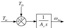
Figures 8 and 9 show the first and second tests, for the maximum and minimum angular rates and constant input rate. The simulation results are reported in literatures [4, 6] for these values. Figures 10 and 11 show the first and second tests, for the maximum and minimum angular rates, online input rate, which derived from the guidance unit. Figure 11 shows the third test, for online input rate and angular rates, at flight path.
5. 2. Gimbal Has Mass Imbalance In this case the gimbal inertia matrix is not diagonal and the disturbance torque is given like what obtained in this equation [4, 6-8]:
2 2
( ) ( )
( ) ( )
e A e m d r A r A d rd A r A d
de A d A e A r re A r A e A d
A T A A A
A A
0 0.05 0.1 0.15 0.2 0.25 0.3 0.35 0.4 0.45 0.5 -0.5 0 0.5 1 1.5 2 2.5
the step response of the stabilization loop
time(sec) th e an gu la r r at e W A e (ra d/ se c) input error simulink
Figure 8. The first test for the maximum values
0 0.05 0.1 0.15 0.2 0.25 0.3 0.35 0.4 0.45 0.5
-0.5 0 0.5 1 1.5 2 2.5
the step response of the stabilization loop
time(sec) th e an gu la r ra te W A e (r ad /s ec ) input error simulink
Figure 9. The second test for the minimum values
0 0.05 0.1 0.15 0.2 0.25 0.3 0.35 0.4 0.45 0.5
-0.5 0 0.5 1 1.5 2 2.5 3 3.5
4x 10 4 time(sec) th e m ax im um a ng ul ar r at e W A e (r ad /s ec ) input error simulink
Figure 10. The first test for the online input rate
0 0.05 0.1 0.15 0.2 0.25 0.3 0.35 0.4 0.45 0.5
-0.5 0 0.5 1 1.5 2 2.5 3 3.5
4x 10 4 time(sec) th e m in im um a ng ul ar r at e W A e (r ad /s ec ) input error simulink
Figure 11. The second test for the online input rate
0 5 10 15 20 25 30 35
-0.5 0 0.5 1 1.5 2 2.5 3 3.5
4x 10
4 time(sec) on lin e an gu la r r at e W A e (ra d/ se c) input error simulink
Figure 12. The third test at flight path
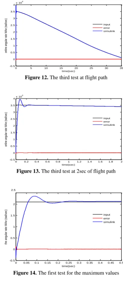
0 0.2 0.4 0.6 0.8 1 1.2 1.4 1.6 1.8 2 -0.5 0 0.5 1 1.5 2 2.5 3 3.5
4x 10
4 time(sec) on lin e an gu la r r at e W A e (ra d/ se c) input error simulink
Figure 13. The third test at 2sec of flight path
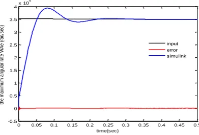
0 0.05 0.1 0.15 0.2 0.25 0.3 0.35 0.4 0.45 0.5
-0.5 0 0.5 1 1.5 2 time(sec) th e an gu la r ra te W A e (r ad /s ec ) input error simulink
Figure 14. The first test for the maximum values
Figures 14 and 15 show the first and second tests, for the maximum and minimum angular rates and constant input rate. The simulation results are reported in literatures [4, 6] for these values. Figures 16 and 17 show the first and second test, for the maximum and minimum angular rates, online input rate, which derived from the guidance unit. Figure 18 shows the third test, for online input rate and angular rates, at flight path.
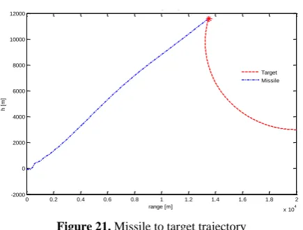
5. 3. Modelled System Constraints When considering the target with constant velocity 450m sand without exercise, from a distance of
30 35
km for different altitudes and approaching tothe site, then, Tables 4 and 5 show the effective range of system modelled for different altitudes. At the end, Figures 20 and 21 show the missile and target trajectory. Figure 20 shows the case when the target is without exercise and Figure 21 shows the case when the target is with exercise. When the missile velocity is lower than the target velocity, is not in effective range.
TABLE 4. Effective range for different altitudes and 30 km
Height (km)
Impact point (m)
missile velocity at impact time (m/s)
Flight time (s)
1 1.735e+04 482.2 28.11
4 1.749e+04 564.78 27.7
6 1.736e+04 601.84 28.09
TABLE 5. Effective range for different altitudes and 35km
Height (km)
Impact point (m)
missile velocity at impact time (m/s)
Flight time (s)
1 1.968e+04 337.47 34.03
3 1.997e+04 388.45 33.39
6 2.006e+04 459.05 33.20
.
0 0.05 0.1 0.15 0.2 0.25 0.3 0.35 0.4 0.45 0.5
-0.5 0 0.5 1 1.5 2 2.5
the step response of the stabilization loop
time(sec) th e an gu la r ra te W A e (r ad /s ec ) input error simulink
Figure 15. The second test for the minimum values
0 0.05 0.1 0.15 0.2 0.25 0.3 0.35 0.4 0.45 0.5
-0.5 0 0.5 1 1.5 2 2.5 3 3.5
4x 10 4 time(sec) th e m ax im um a ng ul ar r at e W A e (r ad /s ec ) input error simulink
Figure 16. The first test for the online input rate
0 0.05 0.1 0.15 0.2 0.25 0.3 0.35 0.4 0.45 0.5 -0.5 0 0.5 1 1.5 2 2.5 3 3.5
4x 10
4 time(sec) th e m in im um a ng ul ar ra te W A e (ra d/ se c) input error simulink
Figure 17. The second test for the online input rate
0 5 10 15 20 25 30 35
-0.5 0 0.5 1 1.5 2 2.5 3 3.5
4x 10 4 time(sec) on lin e an gu la r ra te W A e (r ad /s ec ) input error simulink
Figure 18. The third test at flight path
0 0.2 0.4 0.6 0.8 1 1.2 1.4 1.6 1.8 2 -0.5 0 0.5 1 1.5 2 2.5 3 3.5
4x 10
4 time(sec) on lin e an gu la r r at e W A e (ra d/ se c) input error simulink
Figure 19. The third test at 2 s of flight path
0.5 1 1.5 2 2.5 3 3.5
x 104
-5500 -5000 -4500 -4000 -3500 -3000 -2500 -2000 -1500 -1000 range [m] h [ m ] Target Missile
0 0.2 0.4 0.6 0.8 1 1.2 1.4 1.6 1.8 2 x 10⁴
-2000 0 2000 4000 6000 8000 10000 12000
range [m]
h
[
m
]
Missile and Target Trajectories
Target Missile
Figure 21. Missile to target trajectory
6. CONDLUSION
In this paper, one axis gimbal system with missile dynamics, guidance and control loop is tested for disturbance torque and angular velocities which are online imposed missile frame to seeker. First of all, the airframe dynamics and missile equation of motion is introduced. Then, a model of one axis gimbal system is introduced. The stabilization loop is constructed defining the DC motor, the rate gyro, and the platform. Afterward, guidance law is introduced. The system is modelled using SIMULINK MATLAB to show the validity of the system presented. In this paper, body angular rates and input rate applied to the one axis gimbal system is online. This shows that stabilization loops can isolate the LOS from angular missile motions. Also, the system can track the changes of LOS angle accurately, but the modelled system, only for the effective ranges between
30 35
km can be used. Indeed, for the targets range of 30 km, with different altitudes, it is much better. Also, the system can track the targets with maximum 20 G.7. REFERENCES
1. Chaudhuri, S., Venkatachalam, G. and Prabhakar, M., "Hardware in loop simulation for missile guidance and control systems", Defence Science Journal, Vol. 47, No. 3, (2013), 343-357.
2. Hilkert, J., "Inertially stabilized platform technology concepts and principles", Control Systems, IEEE, Vol. 28, No. 1, (2008), 26-46.
3. Bai, C. and Zhang, Z., "Acceleration-based mass imbalance feedforward compensation for inertial stabilized platform",
International Journal of Control, Automation and Systems, Vol. 12, No. 3, (2014), 609-617.
4. Abdo, M., Toloei, A., Vali, A. and Arvan, M., "Modeling, control and simulation of cascade control servo system for one
axis gimbal mechanism", International Journal of Engineering-Transactions A: Basics, Vol. 27, No. 1, (2013), 157-170.
5. Yu, S. and Zhao, Y.-z., "Study on rotational stabilization in a laser tracking system", Journal of Shanghai Jiaotong University (Science), Vol. 14, (2009), 316-320.
6. Abdo, M., Vali, A.R. and Toloei, A.R., "Fuzzy stabilization loop of one axis gimbal system", International Journal of Computer Applications, Vol. 77, No. 3, (2013), 6-13.
7. Arvan, M.R., Abdo, M., Toloei, A.R. and Vali, A.R., "Stabilization loop of one axis gimbal system considering gimbal mass imbalance and gimbal friction", in The 13th Iranian Aerospace Society Conference, Iran. (2014).
8. Toloei, A.R., Abdo, M., Vali, A.R. and Arvan, M.R., "Research on gimbal seeker performance under variable operation conditions", in The 13th Iranian Aerospace Society Conference, Iran. (2014).
9. Rue, A., "Precision stabilization systems", Aerospace and Electronic Systems, IEEE Transactions on, No. 1, (1974), 34-42.
10. Daniel, R., Kurt, W. and Brandon, A., "Mass properties factors in achieving stable imagery from a gimbal mounted camera",
Published in SPIE Airborne Intelligence, Surveillance, Reconnaissance (ISR) Systems and Applications V, Vol. 6946, (2008).
11. Khamis, A., Naidu, D.S. and Kamel, A.M., "Nonlinear optimal tracking for missile gimbaled seeker using finite-horizon state dependent riccati equation", International Journal of Electronics and Telecommunications, Vol. 60, No. 2, (2014), 165-171.
12. Mondal, S., Sadhu, S. and Banerjee, A., "Platform motion disturbances attenuation in a missile seeker subsystem using internal model control", in Control, Automation, Robotics and Embedded Systems (CARE), International Conference on, IEEE. (2013), 1-4.
13. GÜNER, D.R.L., "Modeling of a generic laser guided weapon with velocity pursuit guidance and its performance analysis using various control strategies", Middle East Technical University, (2004),
14. Akkal, E., "Control actuation systems and seeker units of an air-to-surface guided munition", Middle East Technical University,
(2003),
15. Gorecki, R., "A baseline 6 degree of freedom (DOF) mathematical model of a generic missile, DSTO Systems Sciences Laboratory, (2003).
Effects of Flight Dynamics on Performance of One Axis Gimbal System,
Considering
Disturbance Torques
M. Pirzadeh a, A. R. Toloei b, A. R. Vali c
a Department of Electrical Engineering, Damavand Branch, Islamic Azad University, Damavand, Iran b Department of Aerospace, Shahid Beheshti University, Tehran, Iran
c Department of Electrical Engineering, Malek-Ashtar University of Technology (MUT), Tehran, Iran
P A P E R I N F O
Paper history:
Received 06 June 2015
Received in revised form 28 July 2015 Accepted 30 July2015
Keywords:
Gimbal Seeker Rate Gyro Servo-Tracking Loop LOS Rate
Flight Path
ديكچ ه
یم هدافتسا هقوط زاسرادیاپ مزیناکم متسیسزا ،هقوط یور هدش هدادرارق مسج کی یرادیاپ نیمأت روظنم هب متسیس نیا .ددرگ
تکرح زا مسج ندرک هلوزیا یانبم رب هیواز یاه
یم لمع انبم شزرل و یا کت رکیس لدم میراد دصق هلاقم نیا رد .دیامن
وحم ،تسا بلص مسج هقوط هکنیا ضرفاب ،هقوط رواتشگ طباور .میئامن یفرعم هدنرپ ءیش زاورپ کیمانید هارمه هب ار هر
زا هدافتسا اب متسیس .تسا هدمآ تسدب نتوین مود نوناق طسوت
MATLAB/SIMULINK
رد .تسا هدش یزاسلدم
مع یور زاورپ کیمانید تارثا لیلحت و هیزجت ،قیقحت نیا فده ،تقیقح هیبش جیاتن .تسا هروحم کت هقوط متسیس درکل
و ثحب دروم ار نآ ،زاورپ ریسم یط رد هدش یفرعم ۀروحم کت هقوط متسیس درکلمع تحص نداد ناشن تهج یزاس
یم رارق یسررب مه .دهد
یم ناشن جیاتن نینچ دید طخ هقوط زاسرادیاپ متسیس هک دهد
اهرواتشگ شاشتغا روضح نامز ،
یم رثا متسیس درکلمع یور .دراذگ
![Figure 3. One axis inertial stabilized platform [4, 6, 7]](https://thumb-us.123doks.com/thumbv2/123dok_us/224404.2016984/3.595.316.528.349.419/figure-axis-inertial-stabilized-platform.webp)