Please cite this article as: M. Yari Esbouei, Y. Hezarjaribi, B. A. Ganji, Simulation and Modeling of a High Sensitivity Micro-electro-mechanical Systems Capacitive Pressure Sensor with Small Size and Clamped Square Diaphragm, International Journal of Engineering (IJE), TRANSACTIONS C: Aspects Vol. 30, No. 6, (June 2017) 846-850
International Journal of Engineering
J o u r n a l H o m e p a g e : w w w . i j e . i r
Simulation and Modeling of a High Sensitivity Micro-electro-mechanical Systems
Capacitive Pressure Sensor with Small Size and Clamped Square Diaphragm
M. Yari Esbouei*a, Y. Hezarjaribia, B. A. Ganjib
a Department of Electrical Engineering, Golestan University, Golestan, Iran
bDepartment of Electrical Engineering, Babol Noshirvani University of Technology, Babol, Iran
P A P E R I N F O
Paper history:
Received 03 February 2017
Received in revised form 04 April 2017 Accepted 21 April 2017
Keywords:
Micro-electro-mechanical Capacitive Pressure Sensor Small Size
High Sensitivity Mechanical Coupling
A B S T R A C T
This paper proposes a Micro-electro-mechanical (MEMS) capacitive pressure sensor that relies on the movable electrode displaced like a flat plate equal to the maximum center deflection of diaphragm. The diaphragm, movable electrode and mechanical coupling are made of polysilicon, gold and Si3N4,
respectively. The fixed electrode is gold and the substrate is Pyrex glass. This proposed method increased the effective surface of capacitor and the displacement of movable electrode. The size of this sensor is 250×250 µm2 and the thickness of diaphragm is 1µm with 1 µm air gap. According to the results the sensitivity of sensor is 58.5 𝑓𝐹
𝑚𝑚𝐻𝑔.
doi: 10.5829/ije.2017.30.06c.04
1. INTRODUCTION1
In the past years MEMS capacitive pressure sensors have received increasing attention due to several advantages such as: low temperature sensitivity, good DC response and stability, low power consumption [1-3]. The capacitive pressure sensor is used for advanced industrial, military, automotive, medical applications, control systems and process control. During these years many different designs have been proposed for increasing sensitivity based on the reduction of diaphragm stiffness with different structures and different materials. The common shape of diaphragms are square and round. But in general, the capacitive pressure sensors contain a thin flexible plate as a diaphragm and a fixed plate as a second electrode of capacitive that these plates are separated each other by a small air gap for pressure sensing [3-7].
In MEMS capacitive pressure sensor when the external pressure is applied on diaphragm, the
*Corresponding Author’s Email: [email protected](M. Yari Esbouei)
diaphragm is deflected and changes the air gap between two plates. So, deflection of the diaphragm due to the applied pressure is sensed and translated into an electrical capacitance change. Then, the appropriate microelectronic circuits convert the capacitance change of capacitor to a useful voltage signal [8].
Generally, the pressure sensitivity of capacitive pressure sensor is increased by reducing diaphragm thickness and air gap, increasing diaphragm size. But some of these elements are limited in different devices that
deployed in medical applications. Analyses of capacitance
changes are so effective on sensitivity of capacitive sensor in the different designs. Therefore, modeling of capacitance is necessary that it requires more knowledge about mechanical deflection of sensor’s structure. The behaviors of the flat clamped diaphragms are investigated using the classical Timoshenko plate theory [9]. Also, during many years, many researchers have improved small and large deflection analysis for plates [2, 3, 10].
sensor sensitivity and the mechanical analysis prove the simulation results.
2.SENSORDESIGN
A new design of MEMS capacitive pressure sensor with square diaphragm is shown in Figure 1. This pressure sensor consists of a thin diaphragm with clamped edges for sensing pressure and a pair of plates, one free edges movable electrode and one fixed electrode, for capacitance sensing.
As shown in Figure 1, the h, d0, 2a are the diaphragm thickness, the distance between the pair of capacitor plates and the diaphragm side length, respectively.
2. 1. Mechanical Analysis According to Figure 2, the boundary conditions for the square diaphragm with clamped edges can be expressed as follows [9]:
W(x=a; y) = 0, W(x; y=a) =0, ∂w
∂x (x=a; y) =0, 𝜕𝑤
𝜕𝑥(𝑥; 𝑦 = a) =0
(1)
Under these conditions the central deflection, W0, of a clamped square diaphragm with residual stress due to pressure, P, is given in literature [2]:
P= [3.45𝜎0ℎ
𝑎2 +4.06
𝐸̃ℎ3
𝑎4(1−𝜈2)] w0+ [1.994fs (𝜈) 𝐸̃ℎ
𝑎4] w03 (2) where 𝜎0 and 𝜐 are the residual stress and the poisson ratio that depend on the diaphragm material.
Figure 1. Cross section view of pressure sensor
Figure 2. Cross section view of diaphragm and movable plate
The effective young’s modulus, 𝐸̃, and the poisson ratio dependent function, 𝑓𝑠, expressed as:
𝐸 ̃= 𝐸
1−𝜈2 (3)
fs (𝜈)= 1−0.271𝜈
1−𝜈 (4)
At this design, the initial capacitance between the fixed and movable electrode is given by:
C
0=
𝜀𝐴
𝑑0 (6)
where 𝜖 is the dielectric constant and A is the effective area of the electrodes. Generally the capacitance of pressure sensor that made of two parallel electrodes with clamped diaphragm due to external pressure is given in literature [9]:
C=∬𝑑−𝑤(𝑥,𝑦)𝜀 𝑑𝑥 𝑑𝑦 (7)
where w(x,y) is the diaphragm deflection. But at this new design, the free edges movable electrode attached to diaphragm with mechanical coupling, displaced like a flat plate. This displacement is linear and equal to the deflection at the center of the diaphragm. Therefore the capacitance at this new design due to external pressure is given by:
C= 𝜀𝐴
𝑑0−𝑤0 (8)
For pressure sensor, the capacitance sensitivity can be defined as following:
Sc =
∆𝐶
∆𝑃 (9)
where ∆c is the change in capacitance that given by:
Δ𝐶= C- C0 =
𝜀𝐴
𝑑0−𝑤0 -
𝜀𝐴
𝑑0 (10)
2. 2 Sensor Structure The new sensor is consist of the polysilicon diaphragm, gold movable electrode and fixed electrode. The properties of the polysilicon that used as the diaphragm material is shown at Table 1 [2, 11]. The mechanical coupling material is 𝑆𝑖3𝑁4. Mechanical coupling attached the center of the movable electrode and diaphragm mechanically but electrically isolated from each other. Also the dimension of diaphragm is 250×250×1 𝜇𝑚3 . The height of air gap is 1𝜇𝑚 and the size of the mechanical coupling is small enough to ignoring the effect on the diaphragm deflection, 5×5×0.1 𝜇𝑚3.
TABLE 1. The properties of diaphragm material
Diaphragm material Young modulus Poisson’s ratio stress
3. SIMULATION OF THE CAPACITIVE PRESSURE SENSOR
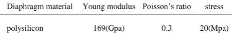
Intellisuite software is used for simulating MEMS capacitive pressure sensor to improve performance and reduce the time of fabrication process. The analysis type is thermo-electro-mechanical relaxation, iteration accuracy is 0.001 and a maximum mesh size is 4𝜇𝑚. Figure 3 shows the simulated sensor with this setup. As shown in Figure 3, the edges of the diaphragm are fixed and movable electrode has free edges. By applying pressure on diaphragm, the movable electrode linearly approaches the fixed electrode.
4.RESULTSANDDISCUSSION
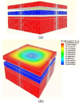
The sample of MEMS pressure sensor, under 40mmHg pressure, is shown in Figure 4. As shown in this figure, when pressure is applied, maximum deflection is in the center of clamped diaphragm. The attachment of movable electrode with free edges and the center of the diaphragm through mechanical coupling cause displacement of the movable electrode without any deflection, like a flat plate, equal to maximum diaphragm displacement.
When pressure is applied, maximum stress is created at the fixed corners of the plates. As can be seen from Figure 4, the corners of the movable electrode are not fixed. Then, this maximum stress does not exist in the edges of movable plate. In this design, this stress only exists at the fixed corners of the diaphragm and fixed electrode. Therefore, this stress does not have an important influence on the displacement of the movable electrode.
This reason increases the effective surface of movable electrode that makes capacitor. On the other hand, since the diaphragm is decoupled from movable electrode by the mechanical coupling, the movable
(a)
(b)
Figure 3. Simulation setup for MEMS capacitive pressure sensor (a) top view (b) side view
(a)
(b)
Figure 4 MEMS capacitive pressure sensor under 40mmHg
pressure (a) side view (b) top view
electrode is displaced equal to center deflection of diaphragm then in addition to increase the effective surface of capacitor, the displacement of the movable electrode increased as well. Therefore, measured capacitance will increase.
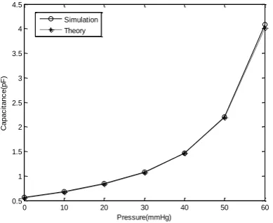
Figure 5 shows the movable electrode displacement, for the range of pressure applied. As can be seen from Figure 5 the simulation results is found to be very close to the theoretical results that are according to Equation (2). Figure 6 shows the simulation and theoretical values of the capacitance between two electrodes due to applying pressure to the diaphragm. The theoretical values are according to Equation (8).
Considering Figure 5, when the applied pressure on the diaphragm is increased, diaphragm deflection is increased too. Figure 6 shows that the capacitance between two electrodes is increased as the air gap is reduced. In this design, according to Equations (9) and (10) and Figure 6, the sensor sensitivity is equal to 58.5
𝑓𝐹
𝑚𝑚𝐻𝑔 .
Therefore, the model is verified to design and analysis of new MEMS capacitive pressure sensor.
Figure 5. Displacement of movable electrode vs. pressure
Figure 6. Capacitance vs. pressure
Figure 7. Capacitance vs. diaphragm thickness
Figure 8. Capacitance vs. diaphragm size
5.CONCLUSIONS
This paper proposed the MEMS capacitive pressure sensor with high sensitivity and small size. In this design, the diaphragm and movable electrode are separated and decoupled to each other with mechanical coupling. Also, no stress exists at the free edges of movable electrode.. Therefore, the movable electrode displaces like a flat plate and has excellent linear variation equal to center deflection of the diaphragm over the pressure.
The device used a polysilicon square clamped diaphragm, the movable and fixed electrodes are gold. Also, the substrate material is Pyrex glass and mechanical coupling is Si3N4.
Structure design model and sensitivity analysis was carried out with simulation and mechanical analysis results. The results show that the theoretical results are close to the simulation results. The size of this sensor is 250×250 µm2 and the thickness of diaphragm is 1µm with 1𝜇 air gap. According to the results, the sensitivity of sensor is 58.5 𝑓𝐹
𝑚𝑚𝐻𝑔 .
6.REFERENCES
1. Zhou, M.-X., Huang, Q.-A., Qin, M. and Zhou, W., "A novel capacitive pressure sensor based on sandwich structures", Journal of Microelectromechanical Systems, Vol. 14, No. 6, (2005), 1272-1282.
2. Rahman, M.M. and Chowdhury, S., "Square diaphragm cmut capacitance calculation using a new deflection shape function", Journal of Sensors, Vol. 2011, (2011).
3. Zhang, Y., Howver, R., Gogoi, B. and Yazdi, N., "A high-sensitive ultra-thin mems capacitive pressure sensor", in Solid-State Sensors, Actuators and Microsystems Conference (TRANSDUCERS), 16th International, IEEE., (2011), 112-115.
0 10 20 30 40 50 60
0 0.1 0.2 0.3 0.4 0.5 0.6 0.7 0.8 0.9
Pressure(mmHg)
D
is
p
la
c
e
m
e
n
t(
u
m
)
Simulation Theory
0 10 20 30 40 50 60
0.5 1 1.5 2 2.5 3 3.5 4 4.5
Pressure(mmHg)
C
a
p
a
c
it
a
n
c
e
(p
F
)
Simulation Theory
1 1.5 2 2.5 3 3.5 4 4.5 5
0.5 0.6 0.7 0.8 0.9 1 1.1 1.2 1.3 1.4 1.5
h(um)
C
a
p
a
c
it
a
n
c
e
(p
F
)
simulation theory
50 100 150 200 250
0 0.5 1 1.5
2a(um)
C
a
p
a
c
it
a
n
c
e
(p
F
)
4. Eswaran, P. and Malarvizhi, S., "Mems capacitive pressure sensors: A review on recent development and prospective", (2013).
5. Ganji, B.A. and Shahiri, M., "Analytical analysis of capacitive pressure sensor with clamped diaphragm (research note)", International Journal of Engineering-Transactions C: Aspects, Vol. 26, No. 3, (2012), 297-304.
6. Ganji, B. and Nateri, M.S., "Modeling of capacitance and sensitivity of a mems pressure sensor with clamped square diaphragm", International Journal of Engineering Transaction B: Applications, Vol. 26, No. 11, (2013), 1331-1336.
7. Ganji, B.A. and Majlis, B.Y., "Fabrication and characterization of a new mems capacitive microphone using perforated
diaphragm", IJE Transactions B: Applications, Vol. 22, No. 2, (2009), 153-160.
8. Shahiri-Tabarestani, M., Ganji, B. and Sabbaghi-Nadooshan, R., "Design and simulation of high sensitive capacitive pressure sensor with slotted diaphragm", in Biomedical Engineering (ICoBE), International Conference on, IEEE., (2012), 484-489. 9. Timoshenko, S.P. and Woinowsky-Krieger, S., "Theory of plates
and shells, McGraw-hill, (1959).
10. Giovanni, D., "Flat and corrugated diaphragm design handbook, CRC Press, Vol. 11, (1982).
11. Ganji, B.A. and Shahiri-Tabarestani, M., "A novel high sensitive mems intraocular capacitive pressure sensor", Microsystem Technologies, Vol. 19, No. 2, (2013), 187-194.
Simulation and Modeling of a High Sensitivity Micro-electro-mechanical Systems
Capacitive Pressure Sensor with Small Size and Clamped Square Diaphragm
M. Yari Esboueia, Y. Hezarjaribia, B. A. Ganjib
a Department of Electrical Engineering, Golestan University, Golestan, Iran
bDepartment of Electrical Engineering, Babol Noshirvani University of Technology, Babol, Iran
P A P E R I N F O
Paper history:
Received 03 February 2017
Received in revised form 04 April 2017 Accepted 21 April 2017
Keywords:
Micro-electro-mechanical Capacitive Pressure Sensor Small Size High Sensitivity Mechanical Coupling ديكچ ه ای ن هلاقم سح رگ راشف نزاخ ی MEMS ا رد .تسا هداد هئارا ار ی ن حارط ی دورتکلا کرحتم دننام ی ک هحفص تباث تکرح م ی دنک هک م ی ناز هباج اج یی اب ربارب نآ رثکادح هباج اج یی زکرم ی د ی مگارفا د سنج .تسا ی
،مگارفا و کرحتم دورتکلا
لپوک ی گن ناکم ی ک ی ترت هب ی ب لپ ی س یل ی ،نوک و لاط
Si3N4
نچمه .تسا ی ن ، ز و لاط زا تباث دورتکلا ی ر لا ی ه زا ش ی هش ی پی سکر کشت ی ل پ شور .تسا هدش ی داهنش ی ازفا بجوم ی ش ازفا و نزاخ تاحفص رثوم حطس ی ش هباج اج یی دورتکلا کرحتم م ی دوش . هزادنا ی ا ی ن سح رگ ربارب تسا اب 250 × 250 م ی ،عبرمرتمورک تماخض د ی مگارفا 1 م ی رتمورک و هلصاف ی اوه یی 1 م ی رتمورک م ی دشاب اتن اب قباطم . ی ج ساسح ی ت سح رگ 58.5 𝑓𝐹 𝑚𝑚𝐻𝑔 تسا .