Please cite this article as:H. Ghariblu, A. Javanmard, The Effect of Base Position on Maximum Allowable Load of Dual Arm Robots, International Journal of Engineering (IJE), TRANSACTIONS B: Applications Vol. 28, No. 2, (February 2015) 284-289
International Journal of Engineering
J o u r n a l H o m e p a g e : w w w . i j e . i rThe Effect of Base Position on Maximum Allowable Load of Dual Arm Robots
H. Ghariblu*, A. Javanmard
Advanced Mechatronic System Lab., Department of Mechanical Engineering, Engineering Faculty, University of Znajan, Zanjan, Iran
P A P E R I N F O
Paper history: Received 02 October 2013
Accepted in revised form 13 November 2014
Keywords:
Dual-arm Robot Base Position Maximum Load Cooperative
A B S T R A C T
A new computational technique is presented to find the optimal base position of dual arm robots in order to carry maximum allowable load. The maximum allowable load on a desired trajectory is limited by the number of factors such as; actuators torque limits, kinematic constraints, and kinematic redundancy of cooperative manipulators. For a dual arm robot mounted on a rail or table, load workspace (LWS) is introduced as the unionof places where the base can locate and robots carry a load on a desired trajectory. It is possible to increase the maximum allowable load by replacing the base of the arms robots in the LWS. By dividing the LWS into grid points, the base position of the rail mounted dual arm robot considered at each point. Using the Newton-Euler formulation and appropriate procedure, maximum allowable load of the robots in all points of the LWS are computed. Then, by iteration, a smaller subspace near to optimum base position is selected until maximum allowable load and corresponding base position is found with acceptable precision. Finally, the application of the proposed algorithm is presented and verifiedfor two different cases.
doi: 10.5829/idosi.ije.2015.28.02b.15
1. INTRODUCTION1
A single robot can manipulate objects only as far as it can reach with limited load capacity. Most industrial robots are fixed in place, thereby limiting their flexibility for tasks requiring manipulation beyond their workspace. Assembling a robot arm over a rail or XY table can provide extreme layout flexibility and increase the size of the work envelope and reduce joint limit constraint. Railed robots are ideal for robotic applications requiring extended reach and high throughput, including machine tending, material handling, material loading, welding, deburring, trimming, and dispensing. In recent years well known robot manufacturers such as Fanuc, ABB and Yasakawa have introduced different kinds of rail mounted manipulators. On the other hand, cooperative manipulation is an important enhancement to robotic capabilities as a dual-arm robot is enabled to perform more complex tasks, manipulate greater payloads, and span a greater workspace [1, 2]. Recently, Yasakawa Motoman Company has introduced different kinds of
1*Corresponding Author’s Email:[email protected](H. Ghariblu)
dual-arm robot to meet industrial automation needs. These robots might be mounted on railed or moving tables12. Therefore, installing two robotic arms on a
railed or mobile base results a highly redundant system and increases the robotic system capability to perform difficult and complicated manipulation tasks with great ease and speed.
In this work, the effect of base position on maximum allowable load of dual arm manipulators mounted on a rail or XY table is studied,this has not been discussed by prior researchers. Finding the maximum allowable load for robotic manipulators can maximize their efficiency and performance in handling heavy objects. Usually, the main constraint for determining the maximum allowable load for a robotic manipulator is its actuators’ torque limit. Meanwhile, there are other factors that can restrict the maximum load capacity as well as joint constraints, kinematic redundancies, and trajectory accuracy constraints. The issue of determining maximum allowable load of single and multi arm robot
21.Motoman dual arms DA10 and DA20 catalouges, MOTOMAN CORPORATE, Web Site: www.motoman.com.
systems have been investigated by different researchers. For a single robotic manipulator, Thomas et al. [3] used the load capacity as a criterion for sizing the actuators of robotic manipulators at the design stage. Wang and Ravani [4, 5] introduced a computation algorithm of dynamic load carrying capacity based on the inertia effects of load and manipulator motion. They showed that maximum allowable load of a manipulator on a given trajectory is primarily constrained by the joint actuator torque and its velocity characteristics. In their study, maximum load is considered in the neighborhood of robot configuration. Korayem introduced a new formulation to find maximum load capacity for point to point motion of flexible link manipulators [6].
Also, Korayem and Ghariblu have studied maximum allowable load of a mobile manipulator imposing redundancy constraints[7], and stability approach [8]. They have also shown that for a single arm mobile base manipulator, there is a unique position for base of a robot arm to carry the maximum allowable load [9].
For cooperative manipulator, Wang and Kuo [10] formulated the governing dynamic equations and inverse dynamic of the multiple robot system in the joint space based on a coordinate partitioning technique. Their solution for load carrying capacity was based on optimization with solving a small-size linear programming problem, which was limited to local solutions and sensitive to initial predefined trajectory. Ghariblu and Javanmard [11] have introduced a method to determine the maximum allowable load of two arm manipulators for a desired trajectory of the load, subject to both actuator and redundancy constraints.
Section 2 briefly presents the base workspace (BWS) and load workspace (LWS) concepts. In Section 3, we formulate the kinematic and dynamic equationsof two cooperative manipulatorshandling a load. The algorithm to find optimal base position to maximize the allowable load of these robots discussed in Section 4. Finally, in two different case studies the application of the method to increase the maximum allowable rely on base position of dual arms are discussed (Section 5).
2. BASE AND LOAD WORKSPACE
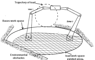
The union of all positions that the common base of arms can be moved and located on them is called the BWS as shown schematically in Figure 1. There exists a subspace of BWS where the base can be located and carries a load on a desired load trajectory. This subspace is defined as load workspace (LWS) and is a function of robots type, their physical dimensions, joint limit and joint actuator constraints. These concepts have been extensively presented and discussed in our before work [6];
3. DYNAMICS OF TWO ARMS HANDLING A LOAD
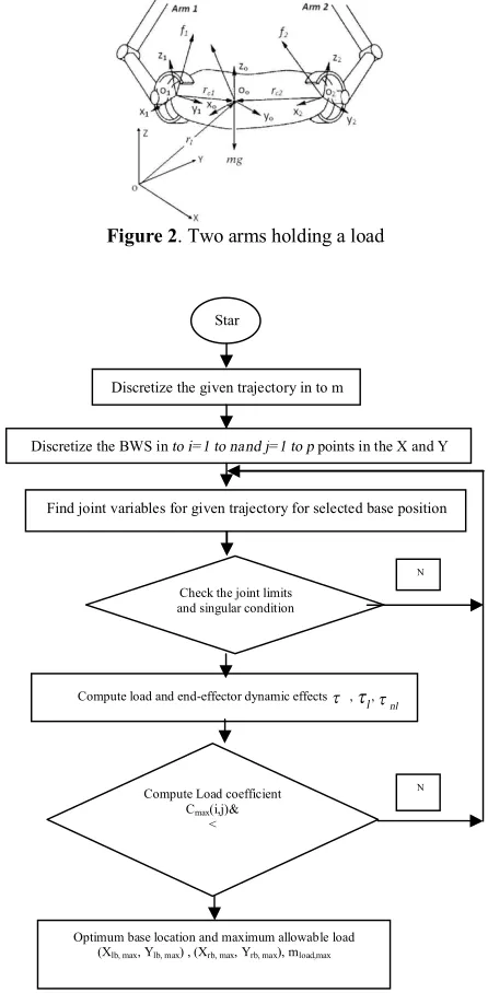
Let us suppose the condition shown in Figure 2 where two arms cooperatively hold a load. Assuming that motion of the load is fully specified, configuration
6
) ,
(r R R
r= l l Î include the load center of mass position rland orientation Rl, and its time derivatives, velocity,
T l l l v V
r&= =( ,w) , and acceleration, T
l l
l v
a
r&&= =(& ,w&) are known prior. Hence, the load equations of motion based on the Newton-Euler formulation have the form:
ú û ù ê ë é ´ + ´ + = ú û ù ê ë é ´ + ú û ù ê ë é ú û ù ê ë é 2 1 1 1 2 1 0 0 0 f r f r f f I v I mI c c l l l l w w
w&& (1)
where, mis the load mass, I, and I are identity and moment of inertia matrices, respectively. f1 and f2denote
the forces at the point acting on the load through the arms and , rc1 andrc2 are the position of the end effectors
all with respect to frame attached at the load center of mass.
Solving Equation(1) for given load trajectory
r
,
r
&
andr
&&
we can compute equivalent f1 and f2.Geometrical constraints between the given load trajectory
r
,
r
&
andr
&&
and their corresponding joint variables nii R
q Î , ,R) R6
l Î , q&i and, q&&i of arm i (i = 1 for the right arm; i = 2 for the left arm), are:
) ( )
( 1 2 2
1 q r q
r
r= = (2)
where ni is the degrees of freedomof arm i.
Differentiating Equation(2) twice by time, leads to:
i i i i i
iq r Jq Jq
J
r&= & , &&=&&+ && (3)
Using Equations (3),
q
&
i andq
&&
ican be written as:) (
, 1 1
1r q J r JJ r
J
q&i= i-& &&i= i- &&-&i i- & (4)
where Ji is the Jacobian matrix to transform the joint
velocity
q
&
iinto the velocity of the frame at the load center of mass.Figure 1. Schematic plan of base workspace and load
The dynamic equation of the arm i,has the form: )
( )
( ) , ( )
( T i
i i i i i i i i i i
i q q C q q q G q J f
M && + & & + =t + - (5)
whereMiis positive definite Inertia matrix, Cia vector
representing centrifugal and Coriolis forces, Gi a vector representing the gravity load and ni
iÎR
t the
corresponding vector of joint torques.
Solving the inverse kinematics and computing,qi,
i
q& andq&&ifrom Equations (2), (3) and (4) and substituting
f1 and f2.executed from Equation (1), joint torques
t
iare computed.
4. OPTIMUM BASE POSITION AND MAXIMUM ALLOWABLE LOAD
In this section, the computational procedure to determine an optimum base location and maximum allowable load of two cooperating arms is outlined. At the first step, the given trajectory of the load and BWS is divided into some grid points. Then, selecting an initial load with a known mass and inertia, the first point of the divided BWS is chosen as the base position. Using kinematic and dynamic equations derived in the previous section, joints variables of two arms are computed for given trajectory.
At the second step, Joints limits are checked as well as singular conditions along with the given trajectory. This base position belongs to the LWS if none of these constraints, are not violated.
Then, total dynamic effects of the load and manipulators on the joint torques τ are computed. Neglecting the force applied to the end effectors, and substitutingf1=f2=0, in the system of Equations (5) the
actuators torque to compensate manipulators dynamics
nl
t
on each joint is computed. By subtractingt
nl from τ, thet
lis obtained:nl
l t t
t = - (6)
The joint actuators upper and lower bounds T(+)andT (-)have the main role in the maximum load carrying
capacity of the robots. Hence, comparing tlwith actuators lower or upper bounds we compute the load coefficient C for the selected base position, as expressed in detail in [14], and omitted here for brevity. The computational procedure to find optimal base position and maximum load is flowcharted in Figure 3.
Selecting a new small subspace of the load workspace in the neighborhood of a place where has the maximum value, and dividing this subspace with higher resolution and repeating the above algorithm, optimal base position and maximum allowable load are found with an acceptable precision.
Figure 2. Two arms holding a load
Figure 3. Flowchart of determining the optimum base location
and maximum allowable load of dual arm manipulators.
5. SIMULATION STUDY
Based on the method presented, two simulation studies was carried out to demonstrate the validity and productivity of the method and proposed algorithm. This algorithm determines optimum base position and maximum allowable load of rail mounted dual arm manipulators.
5. 1. Case 1. Two Cooperative Three-link Planar
Manipulators Numerical simulations are
performed for a rail mounted dual arm three-link planar
Star t
Discretize the given trajectory in to m
Discretize the BWS in to i= 1 to nand j= 1 to p points in the X and Y
Find joint variables for given trajectory for selected base position
Check the joint limits and singular condition
Compute load and end-effector dynamic effects t , tl,
nl
t
Compute Load coefficient Cmax(i,j)&
<
Optimum base location and maximum allowable load
(Xlb, max, Ylb, max) , (Xrb, max, Yrb, max), mload,max
N
manipulators to carry a common load (Figure 4). Two manipulators are similar and link parameters and inertia properties of the manipulators are given in Table 1, while the motor of the actuators are permanent magnet
ِ
motors. For permanent magnet DC motors, there is a linear relationship between torque and speed for a constant voltage:
w w t t
tmotor = s-( s n) (7)
where,
w
n=5 rad/s andt
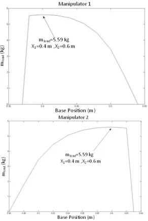
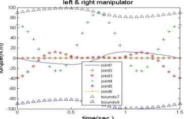
s=60 N.mare no-load speed and stall torques, respectively. The given trajectory is a semi-circle centered at (0.5m , 0.125m ) with respect to the reference frame F1, having a radius of 0.25m .Theobject is required to move along the trajectory with a constant linear velocity of 0.5 m/s and an overall time of motion oft=1.5 s.According to configuration of robots, it is assumed that the base workspace of the manipulator is a line with 1000 mm length along the X coordinates. Dividing the base workspace and given trajectory into equal points, the maximum allowable loadat each base points along the given trajectory is calculated as shown in Figure 5. The optimal base position with coordinate Xleft,man=0.4 m and Xright,man=0.6 m with the maximum load 5.581 kg are found. Figure 6 shows the total torque on each joint actuatorof manipulators on the optimal base position when carrying the maximum allowable load.
Also, in some regions of base workspace it can be seen the value of the mload is zero. This may arise from one of the following problems:
i) The joint limits or actuator constraints are violated. ii) A singular condition occurs when the robot tries to move along its given path.
Therefore, the mobility of the base is an effective way to avoid the joint limits, actuator constraints, and other kinds of singular conditions.
TABLE 1. link parameters and inertia properties of the
manipulators
Link number
Mass ( )
Length
( )
Moment of inertia
( . )
1 4
0.4 0.013
2 5
0. 5 0.026
3 1
0.1 0.0002
Figure 4. Two cooperative three-link planar manipulators
handling a load.
Figure 5. Diagram of the mload versus base position.
Figure 6. Total torque on each joint actuatorof manipulators
5. 2. Case 2. Dual Puma Type Robots In this case,
and their constants are given in Table 3. By dividing the base workspace in both traversing directions and the load trajectory, the maximum allowable load in all base positions along the given trajectory are calculated. At the base position (Xb=-0.4 m, Yb=0.0 m), for robot 1, and (Xb=0.4 m, Yb=0.0 m) for robot 2, the maximum load is found equal to 14.3 kg.
In the next step, a smaller subspace of the LWSin the neighborhood of the optimum base position is chosen, as shown in Figure 8. Then the optimum base location is found at the points coordinate (Xb=-0.4 m, Yb=0.0125 m), for robot 1, and (Xb=0.4 m, Yb=0.0125 m) for robot 2 with mload=14.44 kg. In order to find the base optimum position and its corresponding maximum allowable load with higher precision, the above procedure can be repeated. Figure 9 shows the total torque on each joint actuatorof robots when carrying the maximum allowable load on the optimum base position.
Figure 7. Two cooperative 6 axes puma robots handling a load.
Figure 8. Graph of the m load versus base position.
Figure 9. Total torque on each joint of robots
TABLE 2. Link parameters and inertia properties of puma
robots
Link number
Mass (kg)
Length (m)
Moment of inertia
(kg.m2)
1 4 0.4 0.0133
2 4.5 0.45 0.019
3 1.25 0.125 0.0003
TABLE 3. Actuator constants of puma robots
Actuator number ts (N.m) wn (rad/s)
1 70 10
2 90 15
3 50 7
4 10 1.5
5 10 1.5
6 10 1.5
6. CONCLUSIONS
In this paper, a systematic approach for formulating the governing dynamic equations of a rail mounted dual arm robotic system has been presented. The concepts of base workspace and load workspace introduced for these robotic systems. A general method for computing the optimal base position to carry maximum allowable load of such manipulators is also developed. The method assumes that the payload and end effector trajectory are known prior. It is shown that maximum payload capacity of railed base dual arm manipulators is a function of their base position. Finally, in some case studies, by considering different trajectory for the load the effect of base mobility on optimizing payload capacity in the different kinds of robotic arms is investigated.
It is seen that it is not possible to locate the common base of the dual arms at some distances on the base working space and carry a load in the given trajectory. This is due to constraints on the robot joints and actuators or singular conditions in the manipulator configuration, when it tries to move in its given path. Therefore, the base mobility permits a change in the base position to avoid unwanted constraints of the robotic manipulators.
7. REFERENCES
1. Sun, D. and Mills, J.K., "Manipulating rigid payloads with multiple robots using compliant grippers", Mechatronics,
IEEE/ASME Transactions on, Vol. 7, No. 1, (2002), 23-34.
2. Zivanovic M.D and Vukobratovic M.K., "Multi-arm cooperating robots-dynamics and control, springer, (2006).
3. Thomas, M., Yuan-Chou, H. and Tesar, D., "Optimal actuator sizing for robotic manipulators based on local dynamic criteria",
Journal of Mechanical Design, Vol. 107, No. 2, (1985),
163-169.
applications", Journal of Dynamic Systems, Measurement, and
Control, Vol. 110, No. 1, (1988), 53-61.
5. Wang, L.-T. and Ravani, B., "Dynamic load carrying capacity of mechanical manipulators—part i: Problem formulation",
Journal of Dynamic Systems, Measurement, and Control, Vol.
110, No. 1, (1988), 46-52.
6. Korayem, M., "Optimal trajectory of flexible manipulator with maximum load carrying capacity", International Journal of
Engineering, Vol. 8, No. 4, (1995), 221-232.
7. Habibnejad Korayem, M. and Ghariblu, H., "Maximum allowable load on wheeled mobile manipulators", (2003). 8. Korayem, M., Ghariblu, H. and Basu, A., "Optimal load of
flexible joint mobile robots stability approach", International
Journal of Engineering-Transactions A: Basics, Vol. 17, No.
2, (2004), 193-204.
9. Korayem, M. and Ghariblu, H., "The effect of base replacement on the dynamic load carrying capacity of robotic manipulators",
The International Journal of Advanced Manufacturing
Technology, Vol. 23, No. 1-2, (2004), 28-38.
10. Wang, L.-C. and Kuo, M.J., "Dynamic load-carrying capacity and inverse dynamics of multiple cooperating robotic manipulators", Robotics and Automation, IEEE Transactions on, Vol. 10, No. 1, (1994), 71-77.
11. Ghariblu, H. and Javanmard, A., "Maximum allowable load of two cooperative manipulators", in Computer Engineering and Applications (ICCEA), 2010 Second International Conference on, IEEE. Vol. 2, (2010), 566-570.
The Effect of Base Position on Maximum Allowable Load of Dual Arm Robots
H. Ghariblu , A. Javanmard
Advanced Mechatronic System Lab., Department of Mechanical Engineering, Engineering Faculty, University of Znajan, Zanjan, Iran
P A P E R I N F O
Paper history: Received 02October 2013
Accepted in revised form 13 November 2014
Keywords:
Dual-arm Robot Base Position Maximum Load Cooperative
هﺪﯿﮑﭼ
ريوزﺎﺑودﻪﻨﯿﻬﺑﯽﻫدﺖﯿﻌﻗﻮﻣياﺮﺑيﺪﯾﺪﺟﯽﺗﺎﺒﺳﺎﺤﻣشور و
هﺪﺷﻪﺋاراﺮﺜﮐاﺪﺣرﺎﺑﻞﻤﺣﺖﯿﻠﺑﺎﻗفﺪﻫﺎﺑرﺎﮑﻤﻫﯽﺗﺎﺑ
ﺖﺳا
.
وﯽﮑﯿﺗﺎﻤﻨﯿﺳيﺎﻫﺪﯿﻗ،ﺎﻫرﻮﺗﻮﻣﯽﻟﺎﻤﻋاروﺎﺘﺸﮔﺖﯾدوﺪﺤﻣ،ﺪﻨﻧﺎﻣﻒﻠﺘﺨﻣﻞﻣاﻮﻋزاﯽﻌﺑﺎﺗﻞﻤﺣﻞﺑﺎﻗزﺎﺠﻣرﺎﺑﺮﺜﮐاﺪﺣ تﺎﺟرد رردﯽﻓﺎﺿايدازآ و
ﺖﺳارﺎﮑﻤﻫيﺎﻬﺗﺎﺑ
.
ودﺎﯾو ﯽﻄﺧرﻮﺤﻣﮏﯾردﯽﻠﯾركﺮﺤﺘﻣﻪﯾﺎﭘﮏﯾيورﻪﮐوزﺎﺑودياﺮﺑ
ﮏﯾردرﺎﺑﻞﻤﺣﺖﯿﻠﺑﺎﻗﻪﮐﺖﺳاﻪﯾﺎﭘراﺮﻘﺘﺳايﺎﻀﻓزاﯽﺸﺨﺑزاترﺎﺒﻋرﺎﺑيرﺎﮐيﺎﻀﻓ،هﺪﺷﺐﺼﻧﺪﻣﺎﻌﺘﻣﯽﻄﺧرﻮﺤﻣ درادارمﻮﻠﻌﻣﻞﺒﻗزاﺮﯿﺴﻣ
.
ﯽﻣﻒﯾﺮﻌﺗﻦﯾاﺎﺑ ﺑﻞﺤﻣﻪﺑناﻮﺗ
رﻪﯾﺎﭘراﺮﻘﺘﺳاﻪﻨﯿﻬ و
تﺎﺑ ردزﺎﺠﻣرﺎﺑندﻮﻤﻧﺮﺜﮐاﺪﺣفﺪﻫﺎﺑﺎﻫ
دﺮﮐﻦﯿﯿﺗمﻮﻠﻌﻣﺮﯿﺴﻣﮏﯾ
.
ﻪﮑﺒﺷﻦﯾاطﺎﻘﻧزاﮏﯾﺮﻫردﻪﯾﺎﭘﺖﯿﻌﻗﻮﻣ،رﺎﺑيرﺎﮐيﺎﻀﻓيﺪﻨﺑﻪﮑﺒﺷﺎﺑ،فﺪﻫﻦﯾاﻪﺑﻞﯿﻧياﺮﺑ
ﯽﻣﻪﺘﻓﺮﮔﺮﻈﻧرديﺪﻨﺑ دﻮﺷ
.
ﺲﭙﺳ ، ﻦﺗﻮﯿﻧيﺪﻨﺑلﻮﻣﺮﻓﺎﺑ
–
ﺮﺜﮐاﺪﺣ،ﺐﺳﺎﻨﻣﯽﺗﺎﺒﺳﺎﺤﻣيﻮﮕﻟاوﺮﻠﯾوا ﺮﻫردﻞﻤﺣﻞﺑﺎﻗرﺎﺑ
ﺖﯿﻌﻗﻮﻣزاﮏﯾ ﯽﻣﻪﺒﺳﺎﺤﻣﺎﻫ
دﻮﺷ
.
ﯽﯾﺎﻬﻧﺖﯿﻌﻗﻮﻣ،ﻪﻨﯿﻬﺑﺖﯿﻌﻗﻮﻣﯽﻟاﻮﺣردﺎﻀﻓﺮﯾزﮏﯾﻦﺘﻓﺮﮔﺮﻈﻧردﺎﺑ،ﺪﻌﺑﻪﻠﺣﺮﻣرد
ﯽﻣﻦﯿﯿﻌﺗﺮﻈﻧدرﻮﻣﺖﻗدﺎﺑنآلدﺎﻌﻣرﺎﺑﻞﻤﺣﺖﯿﻓﺮﻇوﻪﯾﺎﭘ دﻮﺷ
.
ﺖﯾﺎﻬﻧرد ، ﯽﺗﺎﺒﺳﺎﺤﻣيﻮﮕﻟادﺮﺑرﺎﮐيدرﻮﻣﻪﻌﻟﺎﻄﻣﺎﺑ
هﺪﺷﻪﺋارا ﯽﻣراﺮﻗﯽﺑﺎﯾزرادرﻮﻣو دﺮﯿﮔ
.