International Journal of Engineering
J o u r n a l H o m e p a g e : w w w . i j e . i r
Performance Investigation of Multi-phase VSI with Simple PWM Switching
Techniques
G. Renukadevi *, K. Rajambal
Department of Electrical and Electronics Engineering, Pondicherry Engineering College, Pondicherry-605 014, India
P A P E R I N F O
Paper history:
Received 5 September 2012
Received in revised form 5 October 2012 Accepted 18 October 2012
Keywords: Harmonic Injection Offset Injection Switching Techniques THD
Voltage SourceInverter
A B S T R A C T
This paper presents the performance of multi-phase voltage source inverter (VSI) with simple PWM switching techniques, namely the harmonic injection and offset injection method. The technique discussed in this paper is easy to implement and avoid complicated controlling algorithm adapted in SVPWM technique. The generalized switching techniques are proposed in this paper. A generalized algorithm suitable for odd number of phases is developed in Matlab/Simulink environment and discussed in detail for both the switching methods. The performance of the 5, 7 and 9-phase VSI is studied with the above-said switching methods. The results of the simulation are presented for different modulation indices and a comparison in terms of fundamental voltage and THD identifies the better scheme suitable for multi-phase inverter fed drives.
doi:10.5829/idosi.ije.2013.26.03c.08
1. INTRODUCTION1
Multi-phase machine drives are increasing rapidly in recent years, due to their several inherent benefits such as lower torque pulsation, reduction in harmonic currents, and increase in current per phase without the need to increase the phase voltage, greater reliability, fault tolerant feature and increased power in the same frame as compared to three phase machine. They are mostly used in high power applications, such as ship propulsion, electric aircraft, and electric/hybrid electric vehicles, etc. Multi-phase motors require multi-phase voltage source inverter (VSI) for their input supply. An inverter topology uses two switches connected in series as one inverter pole. The number of inverter poles depends on number of phases. For example, a three-phase inverter will have three inverter poles whereas a nine-phase inverter will have nine inverter poles. The switching pattern of the three phase inverter should be modified according to the number of phases. For three phase inverters, the sinusoidal pulse width modulation (SPWM) method, space vector pulse width modulation (SVPWM), harmonic injection method and offset
*Corresponding Author Email: [email protected] (G. Renukadevi)
injection method have been extensively discussed in literature [1-21].The SPWM and SVPWM techniques are extended for multi-phase VSI [1-16]. The SPWM schemes are more flexible and easy to implement. However, the output waveforms contain more harmonics resulting in reduced fundamental component and efficiency. To achieve the better output voltage, the several space vector pulse width modulation (SVPWM) techniques are discussed, such as conventional
SVPWM, space vector disposition SVPWM,
discontinuous SVPWM and multi-dimensional SVPWM [4-17]. The complexity involved in the SVPWM technique is more for higher number of phases. The inverter output voltage space vectors changes to 2n
states, since there are 2n different switching
used for multi-phase VSIs. In the harmonic injection method the linear modulation range is extended by adding the mth harmonic component with respective phase of the reference phase voltages and the fundamental output voltage increases without moving into the over-modulation region [18-21]. In the offset injection method, signal generation depends upon the sampled reference phase amplitude and sampling period [5, 22-24]. A comparative study of these two techniques for 5, 7 and 9 phases is considered in this paper.
The simulink model of the multi-phase VSI is presented. The switching schemes based on harmonic injection method and offset injection method are discussed in detail. The performance of the inverter is investigated with these switching techniques and the results are presented for 5, 7 and 9 phases. Based on the simulation results the best scheme is identified in terms of THD and DC bus voltage utilisation.
2. DESCRIPTIONOFMULTI-PHASEVSI
The power circuit diagram of n-phase VSI is shown in Figure 1. The circuit consists of n half-bridges, which are mutually displaced by 2π/n degrees to generate the n-phase voltage waves. The input dc supply is obtained from a single phase or n-phase utility power supply through a diode-bridge rectifier. The voltages Va, Vb, Vc,
Vd, Ve, Vf…Vn are the inverter pole voltages connected to
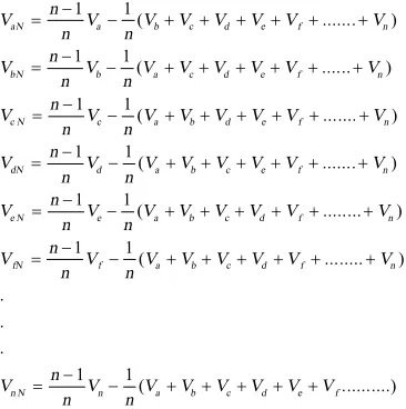
load terminals. It is seen that the switching states of each pole should be combined with each other pole to create the required n-phase output voltages. The load phase voltages and inverter pole voltages is as given in the following relations (1):
1 1( ... )
1 1( ... )
1 1
( ... )
1 1
( ... )
1 1( ... )
aN a b c d e f n
bN b a c d e f n
c N c a b d e f n
dN d a b c e f n
e N e a b c d f n
n
V V V V V V V V
n n n
V V V V V V V V
n n n
V V V V V V V V
n n n
V V V V V V V V
n n n
V V V V V V V V
n n
-= - + + + + + +
-= - + + + + + +
-= - + + + + + +
-= - + + + + + +
-= - + + + + + +
1 1
( ... )
. . .
1 1( ...)
fN f a b c d f n
n N n a b c d e f
n
V V V V V V V V
n n
n
V V V V V V V V n n
-= - + + + + + +
-= - + + + + +
(1)
The harmonic injection method and offset injection method for different number of phases are discussed detail in the following sections.
Figure 1. Power circuit diagram of n-phase VSI
Figure 2. Block diagram of sinusoidal PWM with nth
harmonic injection
3. SINUSOIDAL PWM WITH NTH HARMONIC
INJECTIONFORMULTI-PHASEVSI
To eliminate the 3rd harmonic component in the output of the three phase voltage source inverter, the 3rd harmonic is injected to the sinusoidal reference voltages [1]. This would increase the maximum fundamental output voltage without moving into the over-modulation region. By analogy, the linear modulation range can be extended by injecting the nth harmonic component for n -phase VSI.
The nth-harmonic injection reduces the peak of the n
-leg reference voltages and hence the modulation index can be moved beyond the unity without entering into over-modulation region.
The block diagram of sinusoidal PWM with nth harmonic injection of a n-phase VSI is shown in Figure 2. In the n-phase VSI (Varef, Vbref, Vcref, Vdref…..Vnref) are
reference phase voltages displaced by α= (2π/n) degrees. The reference sinusoidal signals are added with nth
harmonic component to obtain a non-sinusoidal modulating signal. The carrier based modulating signal is compared with the relational operator. The intersections between the modulating signals and the carrier signals give the opening and closing time of inverter switches. The best possible nth-harmonic
( )
( )
( )
( )
( )
[ cos cos ]
[ cos( ) cos ]
[ cos( 2 ) cos ]
[ cos( 3 ) cos ]
[ cos( ) cos ]
a ref nthhar dc n
b ref nthhar dc n
c ref nthhar dc n
d ref nthhar dc n
n ref nthhar dc n
v V M wt M nwt
v V M wt M nwt
v V M wt M nwt
v V M wt M nwt
v V M wt n M nwt
a a a a + + + + + = + = - + = - + = - + = - + M (2)
where M–Modulation index 0£M£1 , Mn–Modulation
index of the nth harmonic component. The mth harmonic
component has no effect on the value of the reference waveform expression when wt=[2k+1] / 2p n, since cos [ [2n k+1] / 2 ]p n =0 for all k. where k=0 to n Hence, Mn can be chosen to make the peak magnitude
of the reference waveform defined in (2) occur where the nth harmonic component is zero, that is wt=p/ 2n.
This would in turn, assure the maximum possible value for the fundamental component. The reference voltages
( )
a ref nthhar
v + reaches maximum when:
( )
sin sin 0
a ref nthha r
dc n dc dv
MV wt nM V nwt
dwt
+ = - - =
(3)
where wt=p/ 2n . From Equation (3)
s i n ( / 2 )
n
n
M M
n p
= - (4)
Under these conditions, the maximum possible non-sinusoidal modulating signal is given by Equation (5)
( )
sin( / 2 )
cos cos
a ref nthhar dc dc dc
n
v MV wt M V nwt V n
p
+ = - = (5)
From Equation (5) M is:
1 c o s( / 2 )
M
n
p
= (6)
4. OFFSET INJECTION METHOD FOR MULTI-PHASE VSI
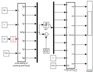
In the offset injection method signal generation depends upon the sampled reference phase amplitude and sampling period. The time duration for different voltages are maintained completely related to the voltage modulation task according to the equal volt-second principle. Therefore, the modulation task can be greatly simplified by considering the relation between the time duration and the output voltage. For that reason, an imaginary time value will be introduced. This value is directly related to the phase voltage and sampling time (Ts), as defined in Equation (7). Figure 3
shows the matlab/simulink model of multi-phase VSI with different switching techniques. The harmonic injection and offset injection method are written by m-file coding and the inverter switches are also programmed in m-file coding.
Figure 3. Matlab/Simulink model of multi-phase VSI
*: : * *: : * *: : * *: : * *: : * *: : *, , , , , ... T s
V V T T T V
a s dc a s s a s Vdc a s
Ts
V V T T T V
bs dc bs s bs Vdc bs
Ts Vcs Vdc Tcs Ts Tcs Vcs
V dc Ts Vds Vdc Tds Ts Tds Vds
V dc Ts
V V T T T V
es dc es s es Vdc es
T s
Vns Vdc Tns Ts Tns Vns n a b c d e V
dc
= Þ =
= Þ =
= Þ =
= Þ =
= Þ =
= Þ = =
M
(7)
Where Vas,Vbs,Vcs,Vds,Ves,Vfs…Vns are the (a,b,c,d,e,f…n)
reference phase voltages, respectively. Tas, Tbs, Tcs, Tes,
Tfs … Tnsare the imaginary switching times of respective
phases. Now, the effective time or offset time (Toffset)
can be defined as the time duration between the smallest and the largest of n- imaginary times, as given by:
max min
offset
T =T -T (8)
max min
max{ , , , , ... } min{ , , , , ... }
as bs cs ds es xs as bs cs ds es xs
T T T T T T T T T T T T T T
=
= (9)
The offset time Toffset should satisfy the following
constraint
min max
0£T +Toffset,T +Toffset£Ts (10)
Therefore, the range of Toffset can be computed as
follows:
minoffset offset maxoffset
T £T £T (11)
where min min max max offset offset s T T
T T T
=
-= - (12)
max min
0.5( )
offset offset offset
n = Number of phases
When the actual gating signals for power devices are generated in the PWM algorithm, there is one degree of freedom by which the effective time can be relocated anywhere within the sampling interval. Therefore, a time-shifting operation will be applied to the imaginary switching times to generate the actual gating times
, , , ,
(T T T T Tga gb gc gd geLTgn) for each inverter pole. This task is accomplished by adding the same value to the offset times as follows:
ga as offset
gb bs offset
gc cs offset
gd ds offset
ge es offset
gn ns offset
T T T
T T T
T T T
T T T
T T T
T T T
= +
= +
= +
= +
= +
= +
M
(14)
5. SIMULATION RESULTS
The n-phase inverter is simulated with the above said firing schemes. The switching frequency of the VSI is chosen as 5 kHz and the fundamental frequency is set to 50 Hz. The simulation results of the individual schemes are discussed and compared in the following sections for different modulation indices.
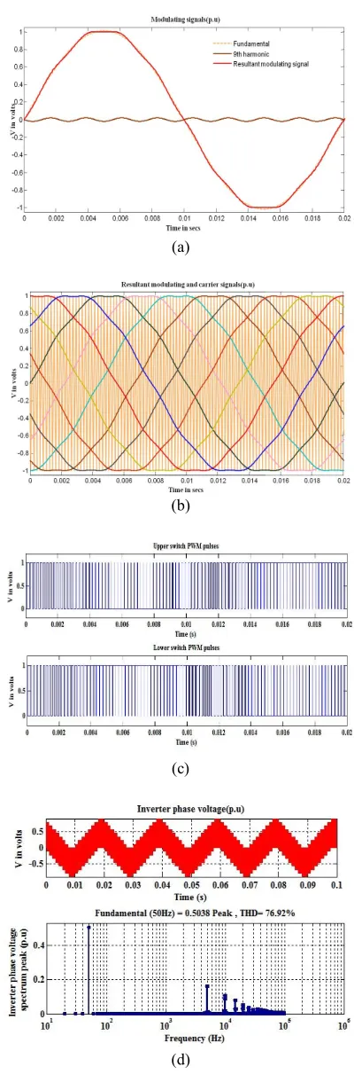
5. 1. Simulation Results with Harmonic Injection Method The 5, 7 and 9-phase VSIs are simulated with the pulses obtained by harmonic injection technique. Figures 4 and 5 shows the results for nine-phase VSI.
Figure 4(a) shows the fundamental, 9th harmonic component waveform and the resultant modulating signal for a modulation index of 1. It is seen that the peak value of the modulating signal is less than 1. It will
reach ±1, when the modulation index
1/ cos( / 2 )
M
=p
n
, according to (4). In addition, this would increase the maximum fundamental output voltage without moving into the over-modulation region. Figure 4(b) shows the modulating signal and carrier wave and the corresponding pulses are presented in Figure 4(c).The output phase voltage and its spectrum are shown in Figure 4(d). It is seen that the output fundamental rms value is 0.3537 p.u. (0.5001 p.u. peak) and THD is 78.01%. The simulation is repeated for the maximum modulation index of 1.01542 and the results are shown in Figure 5(a) to Figure 5(d). It is observed that the output fundamental rms value is 0.3566p.u. (0.5043p.u.peak) and THD is 76.20%. It is seen that the
maximum fundamental output voltage is increased by 1.71% for the maximum modulation index. The 5 and 7 phase VSI are also simulated with this switching technique and the fundamental peak voltage is observed to be increased by 5.15% and 2.85%, respectively.
5. 2. Simulation Results with Offset Injection Method Figures 6 to 9 show the 9-phase VSIs simulated with the pulses obtained by offset injection method.
Figure 6(a) shows the modulating signal and carrier wave and the corresponding pulses are presented in Figure 6(b). The resultant waveform of Tmaxoffset, Tminoffset
and Toffset for the modulation index of 0.9 is presented in
Figure 7. The modulation index is varied from 0.2 to 1.01542 and the Tminoffset and Tmaxoffset are observed and
shown in Figure 8. The modulation index is varied in steps and the Tmaxoffsetand Tminoffset are found for different
modulation index.
It is seen that the Tmaxoffsetand Tminoffset intersecting at
the maximum modulation of 1.01542. The output phase voltage and its spectrum are shown in Figure 9 at this maximum modulation index. It is seen that output
fundamental rms value equals 0.3592p.u.
(0.508p.u.peak). Thus an increase of 2.28% maximum fundamental output voltage is attained in the offset injection scheme. The simulation is repeated for 5 and 7 phase VSI and an increase of 6% and 3.42% in maximum fundamental output voltage is obtained respectively.
5. 3. Comparison of Harmonic Injection and Offset Injection Method Simulation results obtained for different number of phases with the above said switching techniques are compared in terms of fundamental voltage and THD.
Table 1 shows the percentage increase of fundamental voltage. It is noted that the fundamental voltage is marginally high with offset injection method also the increase in voltage reduces with increasing phase number. A maximum of 6% increase is achieved for 5-phase VSI.
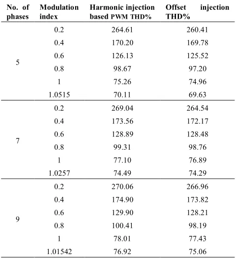
The variation of percentage increase in voltage with number of phases is presented in Figure 10. Table 2 shows the THD for different switching techniques. It is seen that the THD reduction is observed for offset injection method with increasing modulation index. A minimum THD of 69.63% is obtained for 5-phase VSI at maximum modulation index.
(a)
(b)
(c)
(d)
Figure 4. (a) 9th harmonic injection results of fundamental and modulating signals, (b) Carrier and modulating signal components, (c) PWM pulses and (d) Output phase voltage and its spectrum for M= 1
(a)
(b)
(c)
(d)
(a)
(b)
Figure 6. (a)Offset injection results of carrier and resultant modulating signal and (b) PWM pulses for 9-phase VSI MI-1
Figure 7.Tmaxoffset,Tminoffsetand Toffset for MI-0.9
Figure 8.Tmaxoffsetand Tminoffsetfor different modulation indices
Figure 9. Offset injection results of output phase voltage and its spectrum for 9-phase VSI M =1.01542
Figure 10. Percentage increase in fundamental voltage for different number of phases
Figure 11. THD vs. phase number
TABLE 1. Percentage increase in fundamental for different phases
No. of phases
Maximum modulation
index
% increase in fundamental for harmonic injection
% increase in fundamental for
offset injection
5 1.0515 5.15 6
7 1.0257 2.85 3.42
TABLE 2. Comparison of %THD for various PWM techniques
No. of phases
Modulation index
Harmonic injection based PWM THD%
Offset injection THD%
5
0.2 264.61 260.41
0.4 170.20 169.78
0.6 126.13 125.52
0.8 98.67 97.20
1 75.26 74.96
1.0515 70.11 69.63
7
0.2 269.04 264.54
0.4 173.56 172.17
0.6 128.89 128.48
0.8 99.31 98.76
1 77.10 76.89
1.0257 74.49 74.29
9
0.2 270.06 266.96
0.4 174.90 173.82
0.6 129.90 128.21
0.8 100.41 98.19
1 78.01 77.43
1.01542 76.92 75.06
6. CONCLUSION
Two simple PWM techniques namely the harmonic injection and offset injection method suitable for multi-phase VSI are presented. The simulation results are obtained for 5, 7 and 9-phase VSIs. It is found that the linear modulation range is extended without moving into the over-modulation region for both methods. This result is an increase in fundamental voltage. In the offset injection method fundamental voltage is marginally higher than in the harmonic injection method. A maximum of 6% increase in fundamental voltage and minimum THD is observed for 5-phase VSI with offset injection method. The minimum THD and maximum fundamental voltage is obtained for offset injection method in any number of increasing phases. Further the offset injection method eliminates the need for complex control algorithm and its simple calculation makes it easy to implement in digital platform and admirable selection for high power applications.
7. REFERENCES
1. Holmes, G. and Lipo, T., "Pulse width modulation for power converters: principles and practice, IEEE press, (2003). 2. Bose, B. K., "Modern power electronics and AC drives",
Prentice Hall, (2002)
3. Renukadevi, G. and Rajambal, K., "Novel Carrier-Based PWM technique for n-Phase VSI", Journal of Energy Technologies and Policy, Vol. 1, No. 3, (2012), 1-9.
4. Zhou, K. and Wang, D., "Relationship between space-vector
modulation and three-phase carrier-based PWM: a
comprehensive analysis [three-phase inverters]", Industrial Electronics, IEEE Transactions on, Vol. 49, No. 1, (2002), 186-196.
5. Kim, J. S. and Sul, S. K., "A novel voltage modulation technique of the space vector PWM", Transactions-Korean Institute of Electrical Engineers, Vol. 44, No., (1995), 865-874.
6. Kelly, J. W., Strangas, E. G. and Miller, J. M., "Multi-phase inverter analysis", in Electric Machines and Drives Conference, (IEMDC), IEEE International, (2001), 147-155.
7. Iqbal, A. and Levi, E., "Space vector modulation schemes for a five-phase voltage source inverter", in Power Electronics and Applications, European Conference on, IEEE, (2005), 12-18 8. Iqbal, A. and Levi, E., "Space vector PWM techniques for
sinusoidal output voltage generation with a five-phase voltage source inverter", Electric Power Components and Systems, Vol. 34, No. 2, (2006), 119-140.
9. Casadei, D., Serra, G., Tani, A. and Zarri, L., "Multi-phase inverter modulation strategies based on duty-cycle space vector approach", in Proc. of Ship Propulsion and Railway Systems Conference (SPRTS), (2005), 222-229.
10. Kelly, J. W., Strangas, E. G. and Miller, J. M., "Multiphase space vector pulse width modulation", Energy Conversion, IEEE Transactions on, Vol. 18, No. 2, (2003), 259-264. 11. Moinuddin, S. and Khan, M. R., "Space Vector Model of A
Five-Phase Voltage Source Inverter", in Industrial Technology, (ICIT), International Conference on, IEEE, (2006), 488-493. 12. Grandi, G., Serra, G. and Tani, A., "Space vector modulation of
a seven-phase voltage source inverter", in Power Electronics, Electrical Drives, Automation and Motion, SPEEDAM, International Symposium on, IEEE, (2006), 1149-1156. 13. Casadei, D., Milanesi, F., Serra, G., Tani, A. and Zarri, L.,
"Space vector modulation based on a multidimensional approach for multiphase inverters with an odd number of phases", in Power Electronics Specialists Conference, 2008. PESC 2008. IEEE, IEEE. Vol., No. Issue, (2008), 1351-1357.
14. Shi, R. and Toliyat, H., "Vector control of five-phase synchronous reluctance motor with space pulse width modulation for minimum switching losses", in 36th Industry Applications Conference Annual Meeting (IAS). Vol. 3, (2001), 2097-2103.
15. Yu, F., Zhang, X., Li, H. and Ye, Z., "The space vector PWM control research of a multiphase permanent magnet synchronous motor for electrical propulsion", in Electrical Machines and Systems, (ICEMS), Sixth International Conference on, IEEE. Vol. 2, (2003), 604-607.
16. Ryu, H. M., Kim, J. H. and Sul, S. K., "Analysis of multiphase space vector pulse width modulation based on multiple dq spaces concept", in Power Electronics and Motion Control Conference, (IPEMC), The 4th International, IEEE. Vol. 3, (2004), 1618-1624.
17. Xue, S., Wen, X. and Feng, Z., "A novel multi-dimensional SVPWM strategy of multiphase motor drives", in Power Electronics and Motion Control Conference, EPE-PEMC, 12th International, IEEE, (2006), 931-935.
18. Renukadevi, G. and Rajambal, K., "Generalized model of multi-phase induction motor drive using matlab/simulink", in Innovative Smart Grid Technologies-India (ISGT India), IEEE, (2011), 114-119.
19. Levi, E., "Multiphase electric machines for variable-speed applications", Industrial Electronics, IEEE Transactions on, Vol. 55, No. 5, (2008), 1893-1909.
in Power Electronics Specialists Conference, PESC'06. 37th IEEE, (2006), 1-7.
21. Renukadevi, G. and Rajambal, K., "Comparison of different PWM schemes for n-phase VSI", in Advances in Engineering, Science and Management (ICAESM), 2012 International Conference on, IEEE, (2012), 559-564.
22. Chung, D. W., Kim, J. S. and Sul, S. K., "Unified voltage modulation technique for real-time three-phase power conversion", Industry Applications, IEEE Transactions on, Vol. 34, No. 2, (1998), 374-380.
23. Nho, N. and Youn, M. J., "Comprehensive study on space-vector-PWM and carrier-based-PWM correlation in multilevel invertors", in Electric Power Applications, IEE Proceedings-, IET. Vol. 153, (2006), 149-158.
24. Yuan, D., Xu, G., Hu, B., Xiang, A. and Kang, J., "Research on a novel SVPWM for three-phase VSI", in Vehicle Power and Propulsion Conference, IEEE, (2008), 1-5.
APPENDIX
Parameters of the Multi-phase VSI
Parameters Values
DC voltage 1 p.u
Fundamental frequency 50Hz
Switching frequency 5KHz
Modulation index(MI) 0.2 to1
Maximum modulation index M=1/cos(π/2n)
Number of phases(n) 5, 7 and 9
Performance Investigation of Multi-phase VSI with Simple PWM Switching
Techniques
G. Renukadevi, K. Rajambal
Department of Electrical and Electronics Engineering, Pondicherry Engineering College, Pondicherry-605 014
P A P E R I N F O
Paper history:
Received 5 September 2012
Received in revised form 5 October 2012 Accepted 18 October 2012
Keywords: Harmonic Injection Offset Injection Switching Techniques THD
Voltage SourceInverter
هﺪﯿﮑﭼ
يزﺎﻓﺪﻨﭼژﺎﺘﻟوﻊﺒﻨﻣلﺪﺒﻣدﺮﮑﻠﻤﻋﯽﺳرﺮﺑﻪﺑﻪﻟﺎﻘﻣﻦﯾا )
VSI
( ﮏﯿﻨﮑﺗﺎﺑ ،هدﺎﺳﮓﻨﯿﭽﯿﺋﻮﺳيﺎﻫ
PWM
مﺎﻧﻪﺑ، ﻖﯾرﺰﺗ يﺎﻫ
ﯽﻣﺖﺴﻓآﻖﯾرﺰﺗشوروﮏﯿﻧﻮﻣرﺎﻫ دزادﺮﭘ
. ﯽﻟﺮﺘﻨﮐﻢﺘﯾرﻮﮕﻟاﻪﺑيزﺎﯿﻧوهﺪﺷاﺮﺟاﯽﻧﺎﺳآﻪﺑ،ﻪﻟﺎﻘﻣﻦﯾاردﺚﺤﺑدرﻮﻣشور
شوررددﻮﺟﻮﻣهﺪﯿﭽﯿﭘ
SVPWM
ﯽﻤﻧ ﺪﺷﺎﺑ . ﻪﻟﺎﻘﻣﻦﯾارد ﮏﯿﻨﮑﺗ
ﯽﻠﮐﮓﻨﯿﭽﯿﺋﻮﺳيﺎﻫ ﺖﺳاهﺪﺷﻪﺋارا
. ﯽﻠﮐﻢﺘﯾرﻮﮕﻟا
دﺮﻓداﺪﻌﺗﺎﺑﯽﯾﺎﻫزﺎﻓياﺮﺑﺐﺳﺎﻨﻣ ﻂﯿﺤﻣرد،
ﺖﻣ ﺐﻟ درﻮﻣﮓﻨﯿﭽﯿﺋﻮﺳشورودﺮﻫياﺮﺑنآتﺎﯿﺋﺰﺟوهﺪﺷيزﺎﺳﻪﯿﺒﺷ
ﺖﺳاﻪﺘﻓﺮﮔراﺮﻗﯽﺳرﺮﺑوﺚﺤﺑ .
ﻠﻤﻋ دﺮﮑ 5 ، 7 و 9 زﺎﻓ
VSI
،هﺪﺷﺮﮐذﮓﻨﯿﭽﯿﺋﻮﺳشورﺎﺑ، ﻪﻌﻟﺎﻄﻣ
هﺪﺷ ﺖﺳا . ﻪﯿﺒﺷﺞﯾﺎﺘﻧ
ﺺﺧﺎﺷياﺮﺑيزﺎﺳ ﻪﺋاراﯽﺗوﺎﻔﺘﻣنﻮﯿﺳﻻوﺪﻣيﺎﻫ
ويدﺎﯿﻨﺑژﺎﺘﻟوﺮﻈﻧزاو
THD
ﻪﺴﯾﺎﻘﻣ هﺪﺷ ﺖﺳا . ﺐﺳﺎﻨﻣحﺮﻃ ياﺮﺑﺮﺗ
لﺪﺒﻣ يﺎﻫﻮﯾارديزﺎﻓﺪﻨﭼيﺎﻫ
fed
ﺖﺳاهﺪﺷﻦﯿﯿﻌﺗ .