SULFURIC ACID CORROSION OF LOW Sb - Pb BATTERY ALLOYS
by
T. O. Ntukogu
Mechanical Engineering Department University of Nigeria, Nsukka
(Manuscript received February,1983) ABSTRACT
The corrosion properties of low Sb - Pb alloys developed for maintenance free motive power industrial batteries was studied by a bare grid constant current method and compared to those of the conventional Pb- 6% Sb alloy. Low Sb-Pb alloys with Se and As grain refiners were found to have higher corrosion rates than the Pb - 6% Sb alloy or the ternary alloy with Cd which had a comparable corrosion rate with the Pb - 6% Sb alloy. However the ternary alloy was found to have severe grain boundary type corrosion whereas the others had uniform attacks similar to the conventional alloy. The Cd alloy cells were also found to moss, excessively while the cells of the alloy with As did not moss at all. Premature failure could therefore result from using the Cd alloy while only some scarifies to life expectancy could result from using the grain refined alloys in place of the Pb-6% alloy, in batteries.
1. INTRODUCTION
In making lead-acid storage batteries positive and negative plates are made by pasting lead oxides on to a metal grid. Choice of grid metal is very important in maintaining the integrity of the cells. The grid metal must not adversely affect the electrochemistry of the cell, must be strong enough mechanically to with stand the weight of the lead Bxides and must not corrode excessively in a sulfuric acid environment.
Pure lead is ideally suited to the electrochemistry and corrosion requirements of the battery but does not have the mechanical strength. It is therefore strengthened by addition of alloying elements. Pb - 6% Sb alloy has been widely used in conventional motive power batteries. But for the new 'maintenance-free' battery technology, this alloy is not suitable due to the high Sb content. Water loss and therefore battery maintenance is strongly dependent on Sb content of the grid alloy. Development of low maintainance battery grid alloys thus is concerned with reduction or elimination of Sb in the grid
alloys while maintaining properties.
Pb-Ca and Pb-Ca-Sn alloys have been used in stand-by battery applications, but due to their erratic corrosion behaviour, these alloys cannot be used for cyclic applications as in motive power batteries. Motive power maintainance free battery technology is therefore concerned with lowering the Sb content of the Pb-6% alloy while maintaining adequate properties. In this work the corrosion properties of such alloys were examined.
unfortunately even this prediction is further based on an assumption of uniform corrosion attack. Cells can fail prematurely as a result of localized attack so that prevention of such attacks is very important in battery grids.
Localized attacks can result either from a microstructural or casting defects. For Pb-Sb alloys cast- ability becomes a problem at Sb content below 4%, so that addition of another alloying element for improvement of castability may become necessary. Horkers at the research and Development Center of Gould Inc in Chicago Illinois found that addition of Cd improved castability at low Sb contents hence the development of Pb - 1.5% Sb - 1.5% Cd alloy. Unfortunately Cd is an extremely toxic element and handling on industrial level could be quite hazardous. Another alloy with no Cd but containing a small amount of As was developed by workers of National lead Co. A third alloy with neither Cd nor As but containing a small amount of Se and other trace elements was developed in Europe. The corrosion
behaviour of these three alloys was studied in this work and compared to that of Pb - 6% Sb alloy.
2. EXPERIMENTAL CONSIDERATIONS Most of the grid corrosion in batteries occur during the overcharge period. It is therefore possible to induce grid corrosion by simulating over-charge conditions on bare grids. A constant current is applied to unpasted grids in a sulfuric acid electrolyte. This method called a bare grid constant current corrosion
method was used in this work. Ishikawa et a13 showed that under this condition, the corrosion in terms of weight loss increase rapidly initially and then reaches a steady state as
function of time. The initial corrosion is not reproducible for any material whereas the steady state corrosion is material dependent. Data was therefore taken only in the steady state portion of weight loss versus current-time curve. The corrosion orientation was studied metallographically for microstructural dependence while casting effects were eliminated by using only good castings.
Table 1 is the compositions of the 4 alloys used in this work. 75AH (ampere-hour) positive plate size grids of each alloy was made by permanent mold casting technique. The grids were used as cast.
Cell Design
Ten cells were constructed for each alloy as follows: Each cell consisted of 5 grids, 2 positive and 3 negative. The positive grids were weighed and covered with 2 rubber separators held in place by binding strips. Grids were spaced about H" apart by means of properly grooved spacers. Also 2 high bridges were provided at the bottom of each cell to prevent short circuiting. The positive and the negative plates were respectively connected together using pure lead strips welded on to the lug portion of the grids. The cells were filled with 1.285 specific gravity H2S04 electrolyte.
Test Procedure
The usual finishing charging rate for batteries is approximately 5% of the plate capacity so that for 75 Ah size grids, the finishing charging current is approximately 4 amperes (5% of 75 Amp) per plate. Since each cell has 2 positive plates per cell, a current of 8 amps was applied to the cells from a DC power supply with the cells connected in series with an ampere - hour meter.
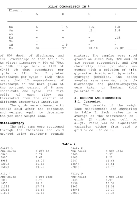
ALLOY COMPOSITION IN % Element
A B C D
Sb 6 1.5 1.6 1.8
Sn - - .2 2.8
As - - -
Eg - - - .18
Se - - .02 -
Cd - 1.5 - -
Pb 94 97 98.18 97.82
of 80% depth of discharge, and 10% overcharge so that for a 75 Ah plate: Discharge = 80% of 75Ah = 60Ah charge back = 110% of 60~66 Ph that overcharge per cycle = 6Ah. For 2 plates overcharge per cycle - 12Ah. This means that 12 ampere-hours of overcharge on the bare grids at the constant current of 8 amps constitute one cycle. The five cells of each alloy was terminated from the circuit at different ampere-hour intervals.
The grids were cleaned with acetic acid after the corrosion and weighed again to determine the per cent weight loss.
Metallography
The grid arms were sectioned through the thickness and cold mounted using Beuhler’s epoxide
mixture. The samples were rough ground on sizes 240, 320 and 600 sic papers successively and then chemically fine polished, and etched with a solution of 4:3:1 glycerine: Acetic acid (glacial): Hydrogen peroxide. The etched samples were examined under the microscope and photomicrographs were taken on Eastman Kodak polaroid films.
3. RESULTS AND DISCUSSION 3.1. Corrosion
The results of the weight loss measurements are summarized in Table 2. Each number is an average of the measurement on 4 grids (2 grids per cell per ally). There was no significant variation either from grid to grid or cell to cell.
Table 2
Alloy A Alloy B
Amp-hours % wgt bs Amp-hours % wgt loss
3045 3.74 3045 3.97
6000 9.62 6003 8.22
8988 13.09 9047 11.66
12003 16.15 13546 16.51
15070 19.75 22012 28.73
Ally C Alloy D
Amp-hours % wgt loss Amp-hours % wgt loss
3012 6.75 3045 4.97
1656 10.9 6196 10.32
11196 17.79 9802 16.01
15264 24.69 13546 20.27
Plots of weight loss as a function of number of cycles for the 4 alloys are shown in Table 3.
Table 3
Alloy Corrosion rate % wgt loss/cyle
A B C D
0.0142 0.0151 0.0186 0.02
Motive power cells using Pb-6% Sb alloys as the positive grid alloy can last up to 1800 cycles from the high temperative accelerated test data. They have also been
mown to last up to 7 2 1
years in
field service before failing by positive grid corrosion. This amounts to 25.56% corrosion ,on the constant current corrosion test mode used in this work. On this basis alloy B will be expected to fail after about 1700 cycles, alloy C after about 1400
cycles and alloy D after about 1300 cycles , Motive Power cells have a life expectancy of 1250 cycles or 5 years. It will therefore appear that alloy B is almost as safe as alloy A while alloys C, and D are
fairly close to the limit.
Maintenance free t motive power cells using alloys C or D might therefore be expected to have lower life expectancies.
3.2 Corrosion Orientation
Metallorgraphic examination
of the corroding edges show that alloy A has a fairly uniform attack as shown in figure 2. Figure 3 is the corroding edge of alloy B showing a strong grain boundary attack. Figures 4 and 5 show the corroding edges of alloys C and D showing fairly uniform corrosion attack again. It is therefore clear that though the corrosion rates of alloy A and B are close, the localized attack in alloy B could result in premature failure when used in a battery .1700 cycles estimated as possible battery life from the corrosion rate may not be obtained and point of fair lure cannot be predicted. It can also be said that the corrosion orientation of alloys A, B, C and D are similar and depend on the substructure and not on the micro-structure.
The differences between the corrosion rates of the alloys as well as their corrosion orientation can be explained on the basis of composition and microstructure. For alloy A which is a binary alloy of Pb and Sb, the Sb rich phase is segregated along dendrite arms in the as cast condition. This means that the grain boundaries are relatively free of the Sb rich phase. Metal dissolution appear to follow the dendritic structure so that it can be said that metal dissolution is via the Sb-rich phase. The uniform appearance of
the corroding edge can be
attributed to the fine dendritic structure of the Pb - 6% Sb alloy. Alloy B on the other hand even though it has a fine dendritic structure as well contains Cd in the dendritic arms. The presence of Cd in the dendritic arms increases
the corrosion resistance of the dendrites relative to the grain bourdaries. Axim, El Sobki and Khedr4 showed that the presence of
Cd in Pb-Sb alloys drastically reduced the corrosion rates in H2S04
medium. Thus the grain boundaries are dissolved easier than the dendrite arms. The coarseness of the grains exposed by the corrosion is a further disadvantage. The deep penetration of the grain boundaries results in the crumbling of the Polycrystalline structure.
Alloys C and D contain small amounts of As and Se respectively. The presence of these two elements serve similar functions in the two alloys as grain refiners. The grain refiner form lead compounds which appear to be localized around the grain boundaries as shown in Figure 6, the microstructure of alloy O. The Sb rich phase in the dendrite arms appear dark while the lead
selenide around the grain
boundaries appear light.
Localization of the grain refiners along the grain boundaries results
in the increase in corrosion
resistance of the grain boundaries relative to the grain interior. Metal dissolution via the dendrite arms therefore results. But the corroding edge is not quite as smooth as in alloy A due to the
relative coarseness of the
dendritic structure. This can also explain the difference in corrosion rates between alloy A on one hand and alloys C and D on the other hand. Larger material are enclosed by the dendrite arms in alloys C and D than in alloy A or B. These materials will be freed to drop into the solution with dissolution of the dendrite arms around it resulting in greater weight loss for alloy C and D than for alloy A in the same length of time.
3.3 Mossing
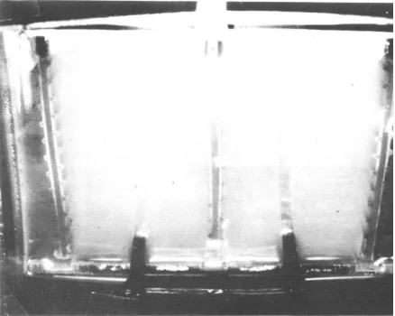
Moss formation was found to depend on the grid alloy. Figure 7 is a typical alloy B cell showing a large amount of mossing at 1700
cycles Alloy B cells showed
excessive amounts of moss. Figure 8 shows a typical alloy D cell with
no moss at all after
Fig. 8.Alloy D cell clean after 1700 cycle
1700 cycles. The amount of mass in alloys A and C cells are moderate.
The high tendency to moss showed by alloy B cells can be related ,to the presence of Cd in the grid alloy. Vinall had pointed out that Cd-Pb alloys had a tendency to form trees when used in battery grids. It is suggested that, Cd acts as a form of catalysts for plating out lead which had gone into the solution during the corrosion on to the negative plates in the form of sponge lead.
On the other hand, the presence of As in alloy D suppresses the process of plating out and hence no moss formation Se did not seem to affect this process, hence massing of Se cells was similar to those of the Pb - 6% Sb cello.
4. CONCLUSIONS
While the presence of Cd in low Sb-Pb alloys increases the
corrosion resistance, the localized grain boundary attack, the very coarse grains as well as the tendency to cause excessive mossing makes the Cd-Sb-Pb alloys undesirable in grid alloys. Low Sb-Pb alloys with grain refiners as in alloys C and D appear to have reliable corrosion properties though not quite as good as those of alloy A. Their use in the maintenance free battery system could therefore be done with some sacrifice to life expectancy when com- pared to maintained cells with the Pb - 6% Sb alloys.
BIBLIOORAPHY
1. Vinal G. W . "Stor-age Batteries" John Wiley & Sons 4th ed. (1955)
2. Maskalick N.J., J.Electrochem.
Soc. 122 19 (1975)
of Evaluating Corrosion test results on grid alloys” Translated by H. Mizukami Communication from Furukuwa Battery Company, Uokohama - Japan (Octo. 1963)