INTRODUCTION
The need to remove a skull bone piece in neurosurgical procedures or the occurrence of its loss as a result of mechanical trauma are the causes of formation need to restore the natural shape of the skull bone. In the major-ity of patients who have experienced the loss of cranial bones, proper supplementing the ap-propriate implants, giving the desired aesthetic effect, so-called cranioplasty operation [13, 15], is an important psychological factor in the recovery and return to normal life in society. Performing trial fit implant constructed should precede the cranial implementation. This process can be carried out in two stag-es: in the virtual world (using 3D models of the skull and of the implant, Figure1a), and in the real world with the use of physi-cal models of the skull and implant using techniques such as 3D printing, Figure 1b.
MATERIALS AND METHODS
Modeling objects with forms that contain no standard geometry (i.e.: plane, patch of analytical surface, sphere, cylinder, cone, etc.) is a very dif-ficult process to achieve using conventional sur-face or solid modeling systems and its tools [22]. One solution to this modeling problem is to use the free surface modeling (nonparametric), where the elements allow to control the shape of the face patches using e.g. control points of the sur-face [14, 22]. However, such modeling methods, are not suitable to solve problems, which concern the scope of this article, i.e. modeling implants matched to difficult skull shape.
In this case (i.e. modeling human skull im-plants based on a discrete skull bone model with a missing piece) the input element to model-ing process of a skull implant is a surface mesh model of the skull obtained from computed tomography (CT) [9–10, 13].
Hybrid Modeling Methods of Cranial Implants
Marek Wyleżoł
11 Institute of Fundamentals of Machinery Design, Silesian University of Technology, Konarskiego 18a., 44-100 Gliwice, Poland, e-mail: [email protected]
ABSTRACT
This article deals with a three hybrid modeling methods of virtual skull implants, developed by the author. 3D models of cranial implants are nowadays necessary for the creation of real implants using modern manufactur-ing technologies. These methods combine simultaneous usage of three modelmanufactur-ing systems (which causes their hybridity): computer tomography system (as a reverse engineering system), surface modeling system and haptic modeling system, and their characteristic modeling methods and techniques. Whereby to commonly used three
different modeling systems we have obtained a synergic effect of the implant shape model quality increasing. The
result of using the developed hybrid methods are models of exemplary cranial implants. The common feature of these methods is that the target virtual model of the cranial implant is always well-suited the coastline of bone hole in the skull. The time of developed of the virtual model of any cranial implant using proposed methods is very shorter compared to use only one of the standard (not medically specialized) computer-aided systems. Similarly, the amount of modeling work is also much smaller than using only one standard 3D system. The article describes hybrid modeling methods developed by the author only.
Keywords: cranial implant, voxel, haptic modeling, CATIA v5, ClayTools Volume 12, Issue 4, December 2018, pages 35–47
https://doi.org/10.12913/22998624/99039
Research Journal
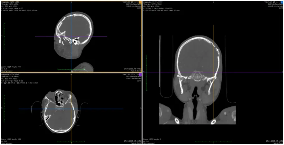
Accepted: 2018.11.05With the type of medical imaging comput-ed tomography (CT) and magnetic resonance (MRI) digital images stored in the standard DI-COM (Digital Imaging and Communications Medicine) files are obtained [8]. Images stored in the extension of the DICOM contain not only graphical data i.e. flat images, but also in-clude patient information and parameters of the medical study. Using the above-mentioned study we receive flat sections of the organ of the hu-man body. The number, size and quality of these cross-sections depend on the settings selected in the medical study. Ideally, when the sections are spaced apart by about 0.5 mm (or less), be-cause then we are able to correctly reconstruct the three-dimensional model of the human body [6].
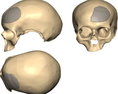
DICOM images (Fig. 2) for obtaining and pro-cessing three-dimensional models are imported
into a specialized program, such as Mimics [16], Osirix [18] or others, where they are processed into 3D models [6, 8–10, 16, 28].
After generating the appropriate masks of the selected area on the bones of the skull layer and after removal of artifacts and performing segmentation we can create a 3D model of the skull first as a voxel model, and next as a STL mesh models. This pro-cess is reconstructive, like reverse engineering [5, 6, 12, 23, 25]. Exemplary STL model of human skull after neurosurgical procedure is shown in Fig. 3.
The described modeling method, which com-bines the capabilities of computed tomography and surface modeling systems, in terms of creat-ing and editcreat-ing 3D elements [14, 20, 22, 27], but also adds many new and – unprecedented in the classical engineering CAx systems (i.e. all engi-neering Computer Aided systems) – possibilities
Fig. 2. View of three planes of human skull (made from DICOM files) after neurosurgical procedure [18]
to shape the virtual models – is a haptic modeling using voxels models [1, 11, 23, 27].
By the author the combination of these three modeling methods and systems gives a positive synergy effect. Thanks to the synergy it is possible to make the models of complex shapes faster and more simply (particularly anatomical models). The combination of these different methods of model-ing means that we can call it hybrid modelmodel-ing. The above-mentioned haptic modeling sys-tems are less known in the world of technology and (even less known) bioengineering so the author focuses on a more accurate presentation of them.
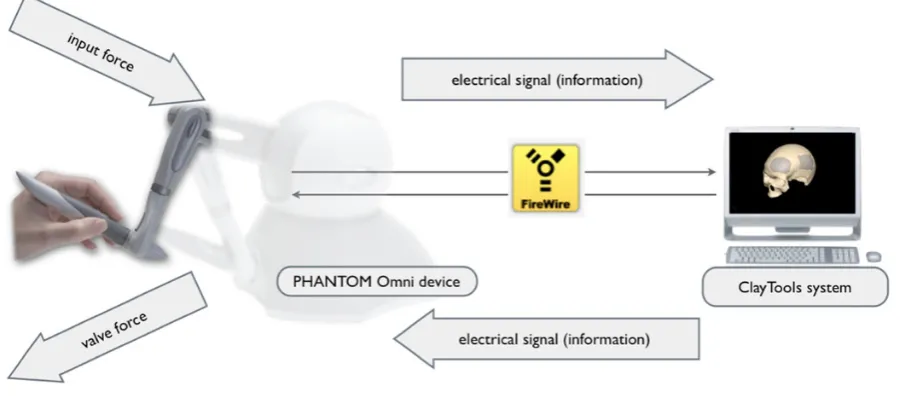
The haptic system includes a set of: a com-puter, software and working with the device – an articulated arm tactile (called: haptic device), as a coupling element of the user’s and software. Some information about the modeling arm called PHANTOM Omni [11]. This device consists of a fixed base and rigid arms pivotally connected. The entire system provides the angular movement of the arms relative to the 6-axis (which gives 6 degrees of freedom, Fig. 4). Joints of the arm are equipped with the sensors recording param-eters of all realized working movements of the us-er’s hand. Additionally, the device has an electri-cally-controlled clutch responsible for generation of friction in the joints, used to obtain a feeling of resistance of the shaped virtual object material.
All the required information signals are trans-mitted in real-time bi-directionally between the
haptic device and its operation control system (via IEEE-1394a FireWire). Information about the operating parameters of the haptic arm move-ments are transferred in the direction of the arm-to-computer model, and the feedback signals – in the opposite direction (fig. 5). All signals sent to the haptic modeling arm give rise to relevant force feedback, noticeable by the user as a resistance in places where the virtual working tip of the arm touches the surface of the virtual voxel model.
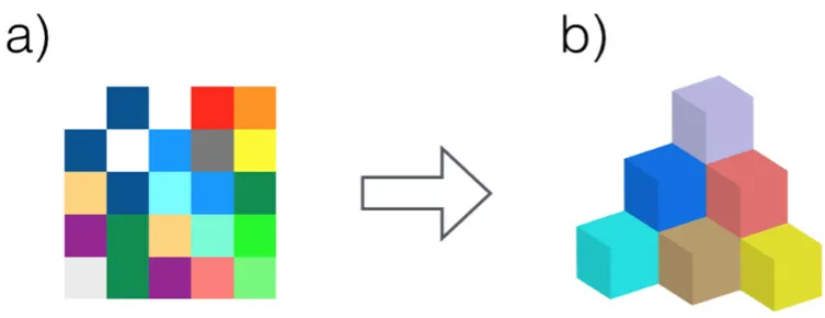
Haptic modeling software tools used to shape virtual models so-called “virtual clay” (popular name of the voxel volumetric model). Voxel is a separate volume element, representing a value on a regular grid in 3D space. This is analogous to a 2D pixel element, which represents image data in a raster graphic. The name derived from the two words: volumetric & pixel (fig. 6). In the other words: voxels are isotropic smallest, indivisible particles, which, arranged in three-dimensional array, create a volumetric form of the model. Spa-tial representation of the voxel is mainly a cube or a rounded cube. Depending on the number of used voxels and their size, representation of the model can be more or less accurate [25, 27].
Voxel representation of model provides not found in other modeling methods (and using oth-er representations of models) ways of shaping the form of models. This advantage is derived from the discrete representation of the model using isotropic voxels. All the activities related to the shaping the voxel model are associated with indi-vidual voxel and their groups. Voxels can be: add-ed to model, subtractadd-ed from the model (fig. 7), moved in the model and scaled in the model.
Voxel modeling reminds shaping plastic mate-rials. There is an analogy to the molecular structure and the characteristics of plastic materials such as clay. Because of this analogy, it is convenient to use just haptic modeling. Haptic modeling allows speeding up the modeling process of very com-plex shapes (especially with no typical geometric shapes) in comparison to the other mentioned mod-eling systems. They allow us to perform even op-erations completely inaccessible in these systems, e.g. CAx systems (where 3D models are described mathematically). Several examples of their use to forming “virtual clay” model are visible in Fig. 8.
As already mentioned, the author’s pro-posal goes in the direction of obtain a hybrid modeling method with the use of three previ-ously mentioned different modeling systems, therefore: reverse engineering (in this case it is
Fig. 3. View of the STL mesh models of human skull
(made from DICOM files) after partial neurosurgical
a computed tomography CT) [6], surface mod-eling [14, 22] and haptic modmod-eling [2, 23, 25]. The effect achieved by the consistent application of these systems is very high
probability of receiving good result (as virtual implant shape precisely matched to the skull hole) then using only one of classical CAx (not medically specialized) systems.
Fig. 5. Haptic modeling system – main elements, connections and direction of signals flow [18]
The scope of the particular systems, di-rections of model’s transformations and ob-tained from them destination models are shown in fig. 9.
RESULTS
As mentioned in the Introduction, surgi-cal implantation of human skull [13, 25] can be planned and carried out its simulation us-ing 3D virtual models of the skull with decline and the implant. Therefore, in the next part of this article attention will be paid to modeling few processes of the 3D skull models’ implants.
Generally accepted assumption of these methods of cranial implants modeling is to have an STL (mesh made) model of the skull with the hole. The skull model is created using the
computed tomography (CT) or magnetic reso-nance imaging (MRI), described in e.g. [8, 10].
In the following part of this article, three modeling methods developed by the author will be presented.
Method No. 1
The basis for the implementation of the follow-up to the creation of the implant model matched to the skull bone with a hole is the use of superficial interpolation spline curves [14, 20, 24, 25, 27]. The possibility to create them on the surface of “virtual clay” (properly: voxel model) gives the haptic system ClayTools [11] too.
Realization of modeling was divided for three main stages [25]:
1. creating curves on the surface of the voxel skull model near the hole,
Fig. 6. The 2D pixel raster (a) and 3D voxel volumetric set (b) [25]
Fig. 7. Examples of voxels deleting: simplified view of the model section and two tools with different penetra
2. implementation of the redundant implant model,
3. implementation of the matched implant model. A scenario can also describe the modeling process structurally. In the scenario we can distinguish: input and output format of the vir-tual models, transitional models’ formats and transformational actions (V – voxelization, WT – wireframe transformation, ST – surface transformation, M – meshing). Scenario of the modeling method no. 1 realization is shown in Fig. 10. Others, more complicated scenarios of modeling processes developed by the author were described in [25].
Stage No. 1
At the first stage of the modeling process we must generate the following features characterizing spline curves:
• generated spline curves are tangent to the surface of the skull model, where the surface between these nodes exist, which curves are
tangent to the surface over its entire length, and not only on the nodes specified by the user, while its absence where (in our case it is a fragment of the skull hole after the re-moval of bone piece), the form of curves is interpolated between the existing neighboring nodes so that the resulting spline curve passes “smoothly” by all appropriate points (Fig. 11);
• the user indicating selected nodes (as points, fig. 12) on the skull model surface to form the spline curve, feeling clear indication of the resistance in place, but it also feels – in the form of resistance on the mentioned haptic de-vice – a kind of “stress” the generated curve.
Stage No. 2
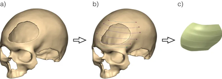
Thus the obtained spline curves (fig. 13b) were used to perform the patch of surface (the second stage of modeling process begins). To do this these splines must be first exported to the general format, such as IGES (Initial Graphics Exchange Specification). The saved set of spline curves has been used to modeling a smooth patch
Fig. 8. Several specific operations of haptic modeling [18]
surface stretched between several splines [14]. The surface modeling process has realized in the environment of module Generative Shape Design of the CAx CATIA v5 system [7]. With the appro-priate software module tools, the surface patch has received adequate thickness (proportional to the thickness of the skull in place to insert the im-plant, Fig. 13c).
As shown in Fig. 13c, the created model of surface patch is much larger than the hole in the skull (Fig. 13a) and has a different shape of the coastline, so it does not seem to fit. At this stage of the action the surface model is actually redun-dant, but – what is very important – includes the desired missing part of the skull.
Thus-formed surface model is transformed into a “virtual clay” (through intermediate conver-sion into a STL file) to give the model final shape into the environment of haptic system. Now we can begin the third stage of the modeling process.
Stage No. 3
Obtaining the desired form of the implant model was made thanks to the “Boolean” sub-traction operation. From a “redundant implant model” (Fig. 14a) was subtracted the volume of the skull model (Fig. 14b). In other words, the existing model of the skull was used to cut the excess volume of the implant model. In this way the implant model matched to existing skull de-fect was obtained (Fig. 14b).
Due to using of pre-modeling of the implant interpolation curves, the implant model shape in several places was a bit redundant and un-matched. This applies particularly to its shape at the edges (constant thickness across the all area). Therefore, the final form of implant fit was achieved using selected software tools of the ClayTools haptic system (including the thick-ness of the implant matched to the thickthick-ness of the skull bone). Furthermore, the model was en-hanced with a set of small through holes. They are
Fig. 10. The scenario of the modeling process realization [25]
necessary to accelerate the reconstruction of bone tissue. The entire destination model was addition-ally completed by elements fixing the implant. All models are visible in Fig. 15. The estimated duration of the implant modeling process is about 1 hours.
Method No. 2
The basis for the implementation of the fol-low-up to the creation of the cranial implant mod-el matched to the skull bone with a hole is the use of superficial interpolation spline curves placed on the inner side of skull model. The possibility to create them on the surface of “virtual clay” gives the haptic system ClayTools [11]. All modeling process is realized together with CATIA v5 [7]. The final implant model is the result of the ability of both of these systems.
Realization of modeling process was divided into five main stages:
1. creating curves on the internal surface of the voxel skull model (near the hole) and
imple-mentation of surface patch,
2. transformation the surface patch to a voxel model
3. adding layers in the place of the blinded (from inside) hole in the skull
4. Boole’an subtraction execution of the skull and additional redundant surface patch.
Stage No. 1
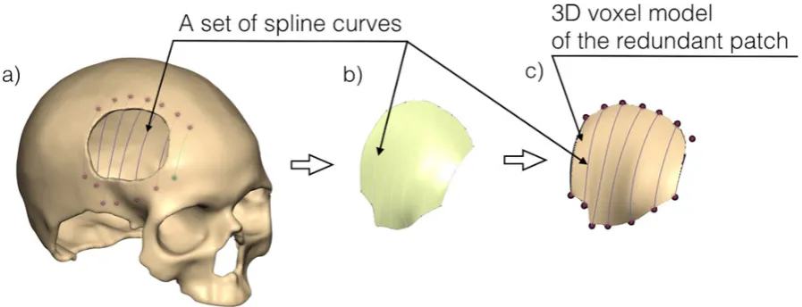
The first stage of this method is similar to the equivalent stage of the Method No. 1. The dif-ference consists in this that we create a curve on the inner side surface of the skull model, near the hole. Obtained spline curves (Fig. 16a) were used to make a model of the auxiliary surface patch. To make this possible, the curves have been pre-viously exported to a neutral format file, such as IGES. The set of curves has been used to model-ing a surface patch, stretched between the curves (Fig. 16b) and next – to give it a constant thick-ness (Fig. 16c). This process has been made in the environment of CATIA v5 Generative Shape Design [7] module.
Stage No. 2
The surface patch was directly converted to voxel model, using the haptic modeling system ClayTools [11]. This voxel surface patch was com-bined with a skull model using Boolean adding.
Stage No. 3
The next stage of implementation of the method is roughing fill the hole depth of the de-fect (Fig. 17b). This process is performed on a copy of the current model (i.e. a separate model of the same geometric form). Incremental layering
Fig. 12. The skull bone voxel model and the surface spline curves
Fig. 13. The first skull bone modeling stages: a) voxel model of the skull, b) set of surface splines, c) initial
is performed using software tools of the haptic modeling system. Implant model and the model of the skull are unitary body. Obtaining the target implant model is done by Boolean subtracting the model with a hole of the model with a layered filling. So obtained implant model is redundant (mainly in the coastal zone), so we should make its final edit.
Stage No. 4
The last stage of the method is the manual removal of redundant fragments of the implant model and execution of the final adjustment to the base model of the skull (Fig. 17).
The presented method is universal and inde-pendent of the place of occurrence of the skull bone loss. Its use is particularly recommended when there is a need to fine-tune the outer part of the implant to the local non-standard (e.g. degen-erative) deformation of the bones of the skull. Es-timated duration of the implant modeling process is about 1.5 hours. The technology of implant production based on such the obtained model is the same as in Method No. 1.
Method No. 3
The basis for the implementation of the fol-low-up to the creation of the following cranial im-plant model matched to the skull bone with a hole (also large) is the use of superficial interpolation spline curves connected in a net and placed on the surface of the “healthy” side of skull model. The possibility to create them on the surface of “virtual clay” gives the same haptic system Clay-Tools [11]. All modeling operations are realized together with CATIA v5 system [7].
Realization of modeling process was divided into three main stages:
1. creation of surface spline curves (as a net-work with common intersection points) and placed on the surface of the “healthy” side of skull model,
2. creation of the redundant implant model, 3. final fitting of the model implant.
Stage No. 1
In the first stage of this method we must ob-tain a net of surface curves placed on the surface of the “healthy” side of skull model. For this pur-pose, we use some special tools of the haptic mod-eling system. The exact location of net curves on the skull model surface is not required. However, one is important: the area “covered” by net curves must be redundant in relation to the area of hole on other side of the skull, relative to the sagittal plane of symmetry (Fig. 18).
Stage No. 2
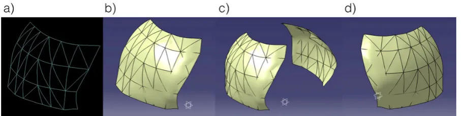
The input to creation of the redundant model of the implant is a net of surface spline curves (Fig. 19a). Using software tools (available in Gen-erative Shape Design module of CATIA v5 system) we create smooth patch surface, stretched between the curves of the net (Fig. 19b). The resulting surface patch should be replicated by a mirrored
Fig. 15. The skull and matched implant model
plane (the sagittal plane, in this case – Fig. 19c). The mirror copy of surface patch (Fig. 19d) will be used to create a redundant implant model.
Before the final stage the surface model will be converted to the form of voxel with a uniform wall thickness (dependent on the thickness of the skull bone near the hole).
Stage No. 3
The end stage of the realization of this method is the same as in the descriptions of the previous methods. Therefore, we use Bool-ean subtraction: from the redundant model of the implant (Fig. 20b) has been subtracted the volume of the skull with hole (Fig. 20c). The result is a 3D model of the implant (Fig. 20d), which requires making only slight correction of its shape.
The third presented method is univer-sal and independent of the place of occur-rence of the skull hole. Estimated duration of the implant modeling process is about 1.0 – 1.5 hours.
DISCUSSION
According to the author, the use of the shown hybrid cranial implant modeling methods is a very universal solution. This versatility mainly relates to the fact that it is possible to reconstruct any deficiency (hole) in the skull, regardless of its lo-cation (as opposed to methods, where the hole to be reconstructed must be only on one side of the sagittal plane, because the second – healthy – side we use to perform a symmetrical reflection). The
Fig. 16. The first stages of the modeling process: a) view of the added spline curves, b) surface patch, c) voxel
form of the surface path
Fig. 17. Views of next modeling stages: a) inner surface of the skull hole, b) adding new additional layer (upon
accuracy of implant fitting to the missing part of the skull is mainly dependent on the quality of the surface curves created. These are spline curves, matched interpolatively by the ClayTools [11] system to the surface of the skull model (where
the surface is) and approximate matching where it is missing (Fig. 11). These curves are export-ed to the CATIA v5 [7] system, where they are used to create surface patches. Thus made surface patches are well-fitting to the missing parts of the
Fig. 19. Views of subsequent stages of surface patch modeling process
Fig. 18. Views of created net of curves on the “correct” side of the skull model surface
Fig. 20. The “Boolean” subtraction
skull. They are always redundant in size. How-ever, this does not in obtaining a well-matched coastline, which is achieved by Boolean opera-tions (as shown in Fig. 14, 17c and 20).
The presented methods are only the first step to obtaining physical cranial implants. Such made voxel models of the cranial implants are usually exported to destination general file format, such as STL. This format is useful for CNC (Comput-erized Numerical Control) milling machine as well as for 3D printing – to produce useful mate-rial models or target implant [1, 3, 17].
In any case the final verification of the im-plant shape should be performed by a neurosur-geon before producing and implanting.
CONCLUSIONS
1. Time of the implants modeling using described hybrid methods (excluding time of obtain the STL skull model using CT process) is – ac-cording to the author’s experience – very short: about 1–1.5 hours.
2. Performance of the shape of the implants – according to the author’s opinion – is impos-sible or very difficult using only one classical computer-aided system (i.e. – not medically specialized systems like EasyCrania, Mimics, 3-Matic e.t.c.).
3. The combination of the three mentioned (gen-eral purposed) modeling systems gives good synergistic effect.
REFERENCES
1. Bonda D.J., Manjila S., Selman W.R., Dean D., Review, The recent revolution in the design and manufacture
of cranial implants: modern advancements and fu-ture directions, Neurosurgery, 2015, 77, 5, 814–824. 2. Bordegoni M., Cugini U., Haptic modeling in the
conceptual phases of product design, VIRTUAL REALITY, 2005, 2–3(9):192–202.
3. Chen J.-J., Liu W., Li M.-Z., Wang C.-T., Digital manufacture of titanium prosthesis for cranioplas-ty, The International Journal of Advanced Manu-facturing Technology, 2006, 27, 1148–1152. 4. Chen X., Xu L., Li X., Egger J., Computer-aided
implant design for the restoration of cranial
de-fects, Scientific Reports, 2017, 7, 1–10.
5. Chrzan R., Urbanik A., Karbowski K, Moskała M.,
Cranioplasty prosthesis manufacturing based on reverse engineering technology, Med. Sci. Monit., 2012, 18, 1, MT1–6.
6. Cierniak M., Computed tomography. Construction of CT. Reconstruction algorithms, Academic Pub-lishing House EXIT, 2006.
7. Dassault Systèmes, 2017, https://www.3ds.com/ products-services/catia. Accessed 01 January 2018 8. DICOM, 2017, http://medical.nema.org. Accessed
30 December 2017
9. Esses S.J., Berman P., Bloom A. I., Sosna J., Clini-cal Applications of PhysiClini-cal 3D Models Derived From MDCT Data and Created by Rapid Proto-typing, American Journal of Roentgenology, 2011, 196, 683–688.
10. Eufinger H., Reconstruction of craniofacial bone
defects with individual alloplastic implants based on CAD/CAM-manipulated CT-data, Journal of Cranio-maxillofacial Surgery, 1995, 23, 175–181. 11. Geomagic®Claytools®, 2016, http://geomagic.
com/en/products/claytools/overview. Accessed 01 September 2017
12. Hieu L.C., Bohez E.,Vander Sloten J., Phien H.N., Vatcharaporn E., Binh P.H., An P.V., Oris P., De-sign for medical rapid prototyping of cranioplasty implants, Rapid Prototyping Journal, 2003, 9,3, 175–186.
13. Karbowski K., Urbanik A., Wyleżoł M., Image
analysis and virtual modeling in designing of skull prosthesis, Mechanik, 2010, 7, 620–622.
14. Kiciak P., Boundary of curves and surfaces model-ing, WNT, 2000.
15. Larysz D., Wolański W., Kawlewska E., Mandera
M., Gzik M., Biomechanical aspects of preopera-tive planning of skull correction in children with craniosynostosis, Acta Bioeng. Biomech., 2012, 14, 2, 19–26.
16. Materialise, 2018, http://biomedical.materialise. com/mimics. Accessed 01 January 2018
17. Moiduddina K., Darwish S., Al-Ahmari A., Ei-Watidy S., Ashfaq M., Ameen W., Structural and mechanical characterization of custom design cra-nial implant created using additive manufacturing, Electronic Journal of Biotechnology, 2017, 29, 22–31.
18. Osirix, 2018, http://www.osirix-viewer.com. Ac-cessed 01 January 2018
19. Parthasarathy J., 3D modeling, custom implants and its future perspectives in craniofacial surgery, Annals of Maxillofacial Surgery, 2014, 4, 9–18.
20. Piegl L., Tiller W., The NURBS book, New York, Springer-Verlag, 1997.
21. Singare S., Lian Q., Ping Wang W., Wang J., Liu Y., Li D., Lu B., Rapid prototyping assisted surgery planning and custom implant design, Rapid Proto-typing Journal, 2009, 15, 1, 19–23.
22. Wełyczko A., CATIA v5. The art of surface model -ing, Helion, 2009.
23. Wyleżoł M., Use of haptic methods in engineer -ing model-ing and analysis – examples, Mechanik, 2009, 11, 948.
24. Wyleżoł M., Modeling of cranial prosthesis,
Mechanik, 2012, 2, 980.
25. Wyleżoł M., Methodology of modeling for reverse
engineering needs, Silesian University of Technol-ogy Publisher, 2013.
26. Wyleżoł M., Muzalewska M., Szczodry B., Com -puter aided and 3D printing in pre-operative plan-ning of orbital reconstruction surgery. Advanced Technologies in Mechanics, 2015, 3, 20–30. 27. Wyleżoł M., Methods of skull implants modeling
![Fig. 3. View of the STL mesh models of human skull (made from DICOM files) after partial neurosurgical reconstruction [18]](https://thumb-us.123doks.com/thumbv2/123dok_us/8805823.1774500/3.595.69.289.70.305/view-models-human-skull-dicom-partial-neurosurgical-reconstruction.webp)
![Fig. 8. Several specific operations of haptic modeling [18]](https://thumb-us.123doks.com/thumbv2/123dok_us/8805823.1774500/6.595.81.524.68.160/fig-specific-operations-haptic-modeling.webp)
![Fig. 10. The scenario of the modeling process realization [25]](https://thumb-us.123doks.com/thumbv2/123dok_us/8805823.1774500/7.595.128.479.598.753/fig-scenario-modeling-process-realization.webp)